1993 DODGE TRUCK ignition
[x] Cancel search: ignitionPage 605 of 1502
8W - 130
WIRING
DIAGRAMS
•
1 2 3
A 4
5 6
7
8
/
9
10
11
/
12 13
14
15 16
/
17
18
19
20
21
u
22
23
24
25 26
u
27
28 29
30
31
u
32 33
34
u
35 36
37
38 39
u
40
41 42
u
VIEW FROM WIRE
END
HEADLAMP
I
DASH
WIRING
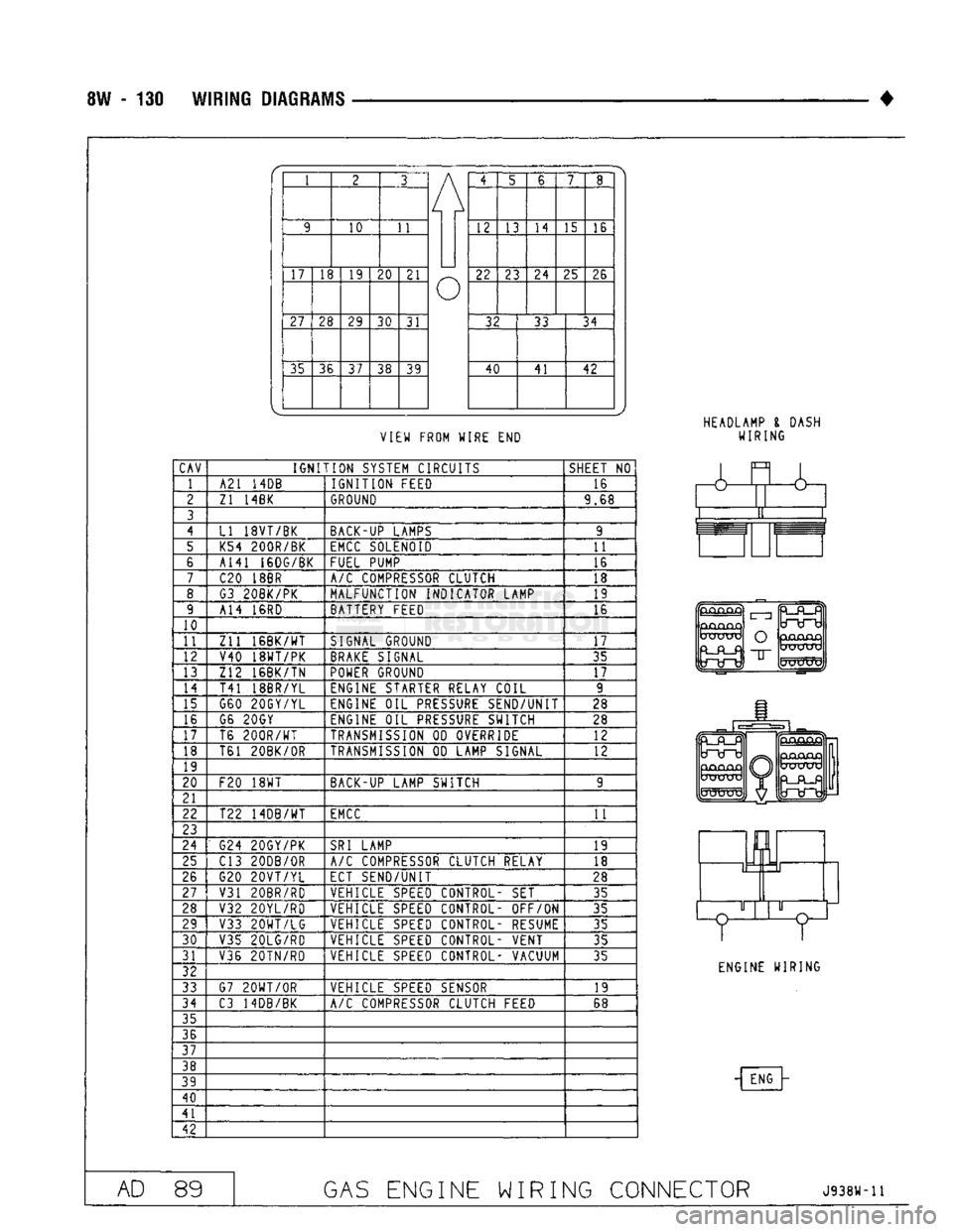
CAV
IGNITION
SYSTEM CIRCUITS
SHEET
NO
1 A21
14DB
IGNITION
FEED 16
2
Zl 14BK
GROUND
9.68
3
4
LI 18VT/BK BACK-UP LAMPS 9
5 K54 200R/BK
EMCC
SOLENOID
11
6 A141 16DG/BK
FUEL PUMP 16
7
C20
18BR
A/C
COMPRESSOR CLUTCH 18
8 G3 20BK/PK MALFUNCTION INDICATOR LAMP 19
9 A14
16RD
BATTERY FEED 16
10
11
Zll
16BK/WT
SIGNAL GROUND
17
12 V40 18WT/PK
BRAKE
SIGNAL 35
13 Z12 16BK/TN
POWER
GROUND
17
14
T41 18BR/YL ENGINE STARTER RELAY COIL 9
15 G60 20GY/YL ENGINE
OIL
PRESSURE
SEND/UNIT 28
16 G6 20GY
ENGINE
OIL
PRESSURE
SWITCH 28
17 T6
200R/WT
TRANSMISSION
OD
OVERRIDE 12
18 T61 20BK/0R
TRANSMISSION
OD
LAMP SIGNAL
12
19
20
F20
18WT
BACK-UP LAMP SWITCH 9
21
22 T22 14DB/WT
EMCC
11
23
24
G24 20GY/PK
SRI
LAMP
19
25 C13 20DB/0R
A/C
COMPRESSOR CLUTCH RELAY
18
26 G20
20VT/YL
ECT SEND/UNIT
28
27
V31 20BR/RD VEHICLE
SPEED
CONTROL-
SET
35
28 V32 20YL/RD VEHICLE
SPEED
CONTROL- OFF/ON
35
29 V33
20WT/LG
VEHICLE
SPEED
CONTROL- RESUME 35
30
V35 20LG/RD VEHICLE
SPEED
CONTROL- VENT
35
31 V36 20TN/RD VEHICLE
SPEED
CONTROL- VACUUM
35
32
33 G7
20WT/0R
VEHICLE
SPEED
SENSOR 19
34
C3 14DB/BK
A/C
COMPRESSOR CLUTCH FEED 68
35
36
37
38
39
40
41
42
&
GjCUQjQ
UXJUXj
O
"IT
mJKXTV
ENGINE WIRING
- ENG
AD
89
GAS
ENGINE WIRING CONNECTOR
J938W-11
Page 607 of 1502

9
- 2
ENGINES
rial surrounds each mounting hole. Excess material
can easily be wiped off. Components should be
torqued in place within 15 minutes. The use of a lo cating dowel is recommended during assembly to pre
vent smearing the material off location.
ENGINE PERFORMANCE
To provide best vehicle performance and lowest ve
hicle emissions, it is most important that the tune-up
be done accurately. Use the specifications listed on
the Vehicle Emission Control Information label found on the engine compartment hood.
(1) Test cranking amperage draw (refer to Group
8B,
Battery/Starter/Generator Service for the proper
procedures).
(2) Tighten the intake manifold bolts (refer to
Group 11, Exhaust System and Intake Manifold for
the proper specifications). (3) Perform cylinder compression test:
(a) Check engine oil level and add oil, if neces
sary.
(b) Drive the vehicle until engine reaches normal
operating temperature. (c) Select a route free from traffic and other
forms of congestion, observe all traffic laws and
briskly accelerate through the gears several times. The higher engine speed may help clean out valve seat deposits which can prevent accurate compres
sion readings.
CAUTION:
DO NOT
overspeed
the
engine.
(d) Remove all spark plugs from engine. As
spark plugs are being removed, check electrodes for
abnormal firing indicators - fouled, hot, oily, etc.
Record cylinder number of spark plug for future
reference.
(e) Disconnect coil wire from distributor and se
cure to good ground to prevent a spark from start
ing a fire.
(f) Be sure throttle blades are fully open during
the compression check. (g) Insert compression gage adaptor into the
No.l spark plug hole. Crank engine until maxi
mum pressure is reached on gauge. Record this
pressure as No.l cylinder pressure.
(h) Repeat Step 3g for all remaining cylinders.
(i) Compression should not be less than 689 kPa
(100 psi) and not vary more than 172 kPa (25 psi)
from cylinder to cylinder.
(j) If cylinder(s) have abnormally low compres
sion pressures, repeat steps 3a through 3h. (k) If the same cylinder(s) repeat an abnormally
low reading, it could indicate the existence of a
problem in the cylinder.
The recommended compression pressures are
to be used only as a guide to diagnosing engine
problems. An engine should NOT be disassem bled to determine the cause of low compression
unless some malfunction is present. (4) Clean or replace spark plugs as necessary. Ad
just gap (refer to Group 8D, Ignition System for gap adjustment and torque).
(5) Test resistance of spark plug cables (refer to
Group 8D, Ignition System.
(6) Inspect the primary wire. Test coil output volt
age,
primary and secondary resistance. Replace parts as necessary (refer to Group 8D, Ignition System and
make necessary adjustment).
(7) Set ignition timing to specifications (refer to
Specification Label on engine compartment hood).
(8) Perform a combustion analysis.
(9) Test fuel pump for pressure and vacuum (refer
to Group 14, Fuel System for the proper specifica
tions).
(10) Inspect air filter element (refer to Group 0,
Lubrication and Maintenance for the proper proce
dure).
(11) Inspect crankcase ventilation system (refer to
Group 0, Lubrication and Maintenance for the proper
procedure).
(12) For emission controls refer to Group 25, Emis
sion Controls System for service procedures.
(13) Inspect and adjust accessory belt drives (refer
to Group 7, Cooling System for the proper adjust
ments).
(14) Road test vehicle as a final test.
H0NIN6
CYLINDER
BORES
Before honing, stuff plenty of clean shop towels un
der the bores and over the crankshaft to keep abra sive materials from entering the crankshaft area.
(1) Used carefully, the Cylinder Bore Sizing Hone
C-823 equipped with 220 grit stones, is the best tool
for this job. In addition to deglazing, it will reduce
taper and out-of-round as well as removing light scuffing, scoring or scratches. Usually a few strokes
will clean up a bore and maintain the required lim
its.
CAUTION:
DO NOT use rigid type
hones
to remove
cylinder
wall
glaze.
(2) Deglazing of the cylinder walls may be done if
the cylinder bore is straight and round. Use a cylin
der surfacing hone, Honing Tool C-3501, equipped
with 280 grit stones (C-3501-3810). 20-60 strokes, de
pending on the bore condition, will be sufficient to
provide a satisfactory surface. Using honing oil C-3501-3880 or a light honing oil available from ma
jor oil distributors.
CAUTION:
DO NOT use engine or
transmission
oil, mineral
spirits
or
kerosene.
Page 610 of 1502
•
ENGINES
9 - S
ENGINE
DIAGNOSIS
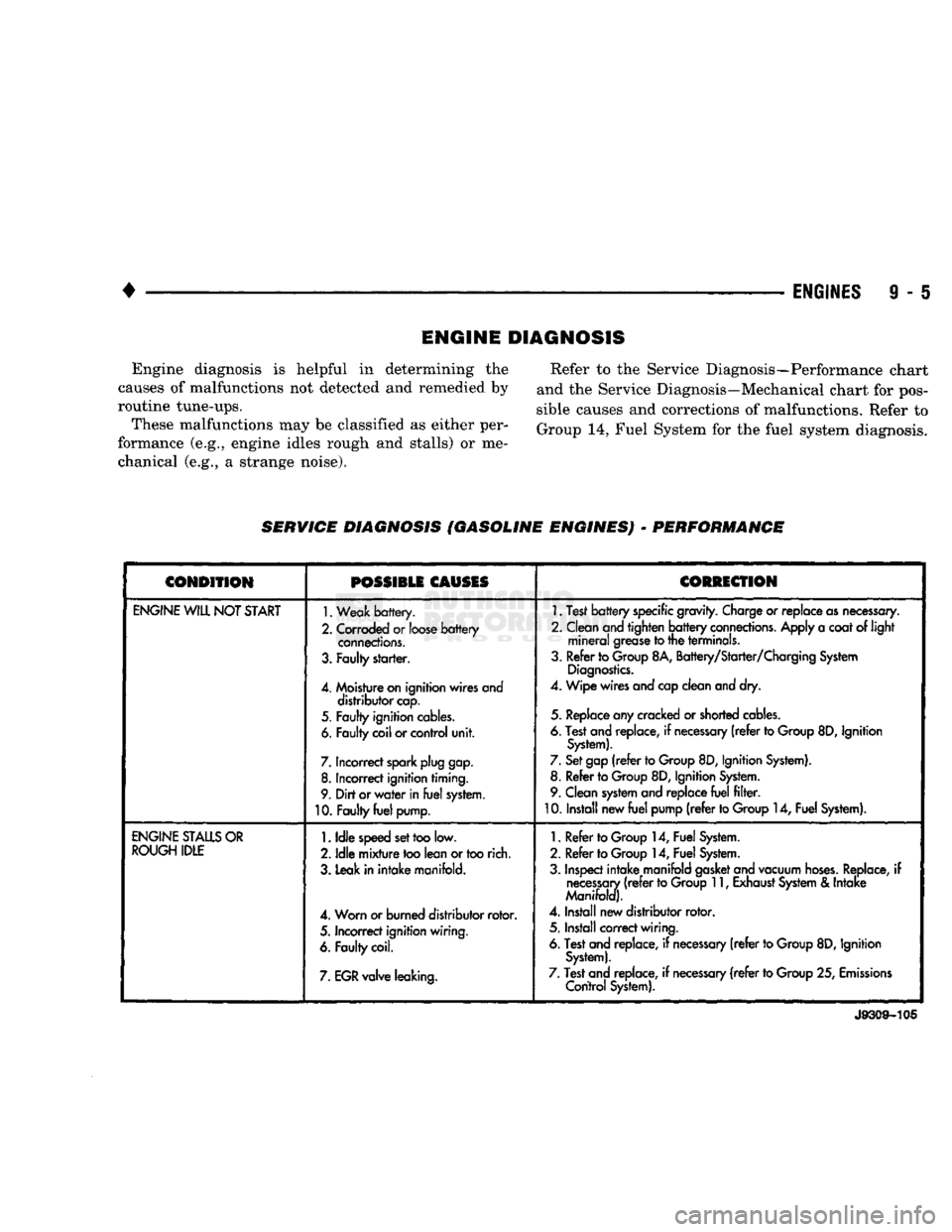
Engine diagnosis is helpful in determining the
causes of malfunctions not detected and remedied by
routine tune-ups. These malfunctions may be classified as either per
formance (e.g., engine idles rough and stalls) or me chanical (e.g., a strange noise). Refer to the Service Diagnosis—Performance chart
and the Service Diagnosis—Mechanical chart for pos
sible causes and corrections of malfunctions. Refer to
Group 14, Fuel System for the fuel system diagnosis.
SERWIGE DIAGNOSIS (GASOLINE ENGINES)
-
PERFORMANCE
CONDITION
POSSIBLE
CAUSES
CORRECTION
ENGINE
WILL
NOT
START
1.
Weak
battery.
2.
Corroded
or
loose
battery
connections.
3.
Faulty
starter.
4.
Moisture
on
ignition wires and distributor
cap.
5.
Faulty
ignition
cables.
6.
Faulty
coil
or
control
unit.
7.
Incorrect
spark
plug
gap.
8.
Incorrect
ignition timing.
9.
Dirt
or
water
in
fuel
system.
10.
Faulty
fuel
pump.
1.
Test
battery
specific
gravity.
Charge
or
replace
as
necessary.
2. Clean
and
tighten
battery
connections.
Apply
a
coat
of light
mineral
grease
to
the terminals.
3. Refer to
Group
8A, Battery/Starter/Charging
System
Diagnostics.
4. Wipe
wires
and
cap
clean
and
dry.
5.
Replace
any
cracked
or
shorted
cables.
6.
Test
and
replace,
if
necessary
(refer
to
Group
8D,
Ignition
System).
7.
Set
gap
(refer
to
Group
8D, Ignition
System).
8. Refer to
Group
8D, Ignition
System.
9. Clean
system
and
replace
fuel
filter.
10. Install new
fuel
pump
(refer
to
Group
14,
Fuel
System).
ENGINE
STALLS
OR
ROUGH
IDLE
1.
Idle
speed
set
too
low.
2.
Idle
mixture
too
lean
or
too
rich.
3. Leak in
intake
manifold.
4. Worn or burned distributor
rotor.
5.
Incorrect
ignition wiring.
6.
Faulty
coil.
7.
EGR
valve leaking.
1.
Refer to
Group
14,
Fuel
System.
2. Refer to
Group
14,
Fuel
System.
3.
Inspect
intake
manifold
gasket
and
vacuum
hoses.
Replace,
if
necessary
(refer
to
Group
11,
Exhaust
System
&
Intake
Manifold).
4.
Install new distributor
rotor.
5. Install
correct
wiring.
6.
Test
and
replace,
if
necessary
(refer
to
Group
8D,
Ignition
System).
7.
Test
and
replace,
if
necessary
(refer
to
Group
25,
Emissions
Control
System).
J9309-105
Page 611 of 1502

9
- 6
ENGINES
•
SERVICE DIAGNOSIS (GASOLINE ENGINES)
•
PERFORMANCE (CONT.)
1
CONDITION
POSSIBLE
CAUSES
^
CORRECTION
1
ENGINE
LOSS
OF
POWER
1.
Incorrect ignition timing.
2. Worn or burned distributor
rotor.
3. Worn distributor shaft.
4.
Dirty
or
incorrectly
gapped
spark
plugs.
5.
Dirt
or
water
in
fuel
system.
6.
Faulty
fuel
pump.
7.
Incorrect valve timing.
8.
Blown
cylinder head
gasket.
9.
Low
compression.
10.
Burned,
warped or
pitted
valves.
11.
Plugged
or
restricted
exhaust
system.
12. Faulty ignition
cables.
13. Faulty coil.
1.
Refer
to
Group
8D, Ignition
System.
2. install new distributor
rotor.
3.
Remove
and
repair
distributor
(refer
to
Group
8D, Ignition
System).
4.
Clean
plugs
and
set gap
(refer
to
Group
8D, Ignition
System).
5. Clean
system
and replace
fuel
filter.
6. Install new
fuel
pump.
7.
Correct
valve
timing.
8. Install new cylinder head
gasket.
9.
Test
compression
of
each
cylinder.
10.
Install new
valves.
11.
Install new
parts,
as
necessary.
12.
Replace
any cracked or
shorted
cables.
13.
Test
and
replace,
as
necessary
(refer
to
Group
8D, Ignition
System).
ENGINE
MISSES
ON
ACCELERATION
1.
Dirty
or
gap set
too
wide
in spark
plug.
2. Incorrect ignition timing.
3.
Dirt
in
fuel
system.
4.
Burned,
warped or
pitted
valves.
5. Faulty coil.
1.
Clean spark
plugs
and set gap
(refer
to
Group
8D, Ignition
System).
2. Refer to
Group
8D, Ignition
System.
3. Clean
fuel
system.
4.
Install new
valves.
5.
Test
and
replace,
if
necessary,
(refer
to
Group
8D, Ignition
System).
ENGINE
MISSES
AT HIGH
SPEED
1.
Dirty
or
gap set too
wide
in spark
plug.
2. Worn distributor shaft.
3. Worn or burned distributor
rotor.
4. Faulty
coil.
5. Incorrect ignition timing.
6.
Dirty
injector
in
throttle
body.
7.
Dirt
or
water
in
fuel
system.
1.
Clean
spark
plugs
and
set gap
(refer
to
Group
8D, Ignition
System).
2.
Remove
and
repair
distributor
(refer
to
Group
8D,
Ignition
System).
3. Install new distributor
rotor.
4.
Test
and replace,
as
necessary
(refer
to
Group
8D, Ignition
System).
5.
Refer
to
Group
8D, Ignition
System.
6.
Clean
injector.
7.
Clean
system
and replace
fuel
filter.
J9309-106
Page 617 of 1502
9
- 12
ENGINES
•
CONDITION
POSSIBLE
CAUSES
CORRECTION
EXCESSIVE
EXHAUST
SMOKE
(Cont'd)
More
than
one
sealing washer
under an injector.
Check
and remove
extra
washer.
Improperly operating injectors.
Check
and replace inoperative injectors.
Improperly operating or over-
fueled injection pump.
Replace
injection pump.
Piston
rings
not sealing
(blue smoke). Perform blow-by check. Correct as required.
ENGINE
WILL
NOT
SHUT-OFF
Fuel shutoff valve inoperative.
Engine
running on fumes drawn into the air intake.
Stop
the engine mechanically
with
lever on the
fuel
pump.
Check/replace
sealing washer, piston and
spring.
Check
the air intake ducts for the source of the fumes.
WARNING:
In
ease
of engine runaway due to flammable
fumes
from gasoline spills or turbocharger oil leaks
being
sucked
into the
engine,
shut off engine ignition switch first then use a CO* or dry
chemical type
fire
extinguisher
and direct the
spray
under
the
front
bumper to
remove
oxygen
supply. The engine air
intake
is on the
passenger
side
behind the bumper. The
fire
extinguisher
must
bo
directed at this location for emergency shutdown conditions.
COOLANT
TEMPERA
TURE
ABOVE
NORMAL
Low
coolant level.
(a) Check coolant level. Add coolant, if necessary.
(b) Locate and correct the source of the coolant leak. Refer to
troubleshooting
logic for coolant
loss.
Incorrect/improperly operating
pressure
cap.
Replace
cap
with
the correct rating for the
system.
High
lube oil level.
Check/drain
oil to correct level.
Loose
drive belt on water
pump/fan.
Check/replace
belt or belt tensioner.
Inadequate air flow to the radiator. Check/repair radiator core, fan shroud and fan clutch as
required.
Radiator
fins
plugged.
Blow
debris from fins.
Collapsed
radiator
hose.
Replace
the
hose.
Improperly operating tempera
ture
sensor/gauge.
Verify
that
the
gauge
and temperature
sensor
are accurate.
Replace
gauge/sensor,
if bad.
Improperly operating, incorrect
or
no thermostat.
Check
and replace the thermostat.
Air
in the cooling
system.
(a) Make sure the
fill
rate
is not being exceeded and the correct
vented thermostat is installed.
(b) Check for loose hose
clamps.
Tighten if
loose.
(c) If aeration continued, check for a
compression
leak through the head gasket.
Inoperative water pump.
Check
and replace the water pump.
incorrect injection pump timing. Verify pump timing marks are aligned. Check/time the injector
pump
(refer
to Group 7,
Cooling
System).
J9209-56
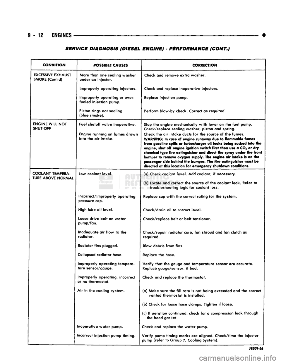
SERVICE DIAGNOSIS (DIESEL ENGINE) - PERFORMANCE (CONT.)
Page 629 of 1502
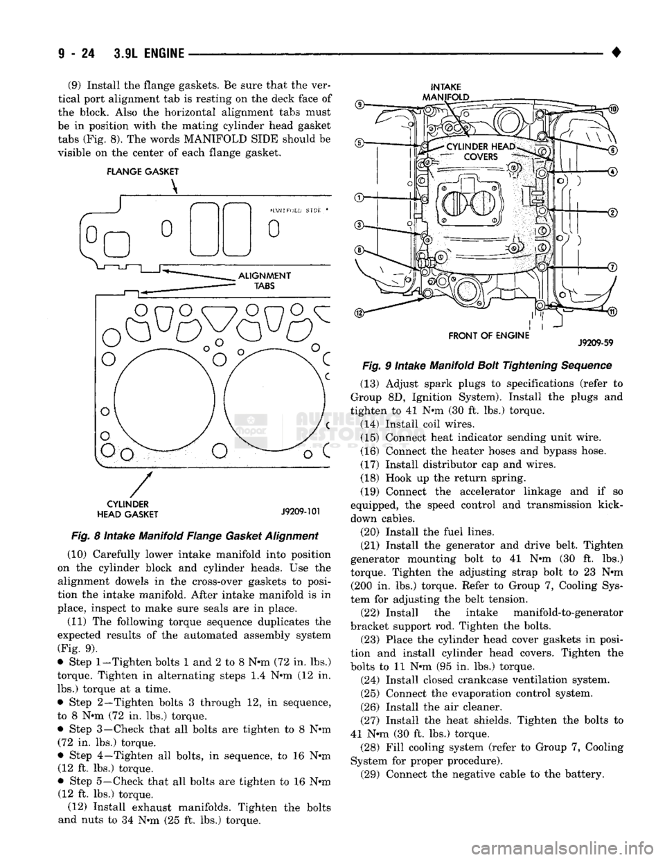
(9) Install the flange gaskets. Be sure that the ver
tical port alignment tab is resting on the deck face of
the block. Also the horizontal alignment tabs must
be in position with the mating cylinder head gasket
tabs (Fig. 8). The words MANIFOLD SIDE should be
visible on the center of each flange gasket.
FLANGE GASKET
INTAKE
AAANIFOLD
CYLINDER
HEAD GASKET
J9209-101
Fig.
8 Intake Manifold Flange
Gasket
Alignment
(10) Carefully lower intake manifold into position
on the cylinder block and cylinder heads. Use the alignment dowels in the cross-over gaskets to posi
tion the intake manifold. After intake manifold is in
place, inspect to make sure seals are in place.
(11) The following torque sequence duplicates the
expected results of the automated assembly system
(Fig. 9).
• Step
1-Tighten
bolts 1 and 2 to 8 N-m (72 in. lbs.)
torque. Tighten in alternating steps 1.4 N-m (12 in. lbs.) torque at a time.
• Step 2—Tighten bolts 3 through 12, in sequence,
to 8 N-m (72 in. lbs.) torque.
• Step 3—Check that all bolts are tighten to 8 N-m (72 in. lbs.) torque.
• Step 4—Tighten all bolts, in sequence, to 16 N-m (12 ft. lbs.) torque.
• Step 5—Check that all bolts are tighten to 16 N-m (12 ft. lbs.) torque. (12) Install exhaust manifolds. Tighten the bolts
and nuts to 34 N-m (25 ft. lbs.) torque.
FRONT OF ENGINE
J9209-59
Fig.
9 Intake Manifold
Bolt
Tightening
Sequence
(13) Adjust spark plugs to specifications (refer to
Group 8D, Ignition System). Install the plugs and
tighten to 41 N-m (30 ft. lbs.) torque.
(14) Install coil wires. (15) Connect heat indicator sending unit wire.
(16) Connect the heater hoses and bypass hose.
(17) Install distributor cap and wires.
(18) Hook up the return spring.
(19) Connect the accelerator linkage and if so
equipped, the speed control and transmission kick-
down cables.
(20) Install the fuel lines.
(21) Install the generator and drive belt. Tighten
generator mounting bolt to 41 N-m (30 ft. lbs.)
torque. Tighten the adjusting strap bolt to 23 N-m (200 in. lbs.) torque. Refer to Group 7, Cooling Sys
tem for adjusting the belt tension. (22) Install the intake manifold-to-generator
bracket support rod. Tighten the bolts. (23) Place the cylinder head cover gaskets in posi
tion and install cylinder head covers. Tighten the
bolts to 11 N-m (95 in. lbs.) torque.
(24) Install closed crankcase ventilation system.
(25) Connect the evaporation control system.
(26) Install the air cleaner.
(27) Install the heat shields. Tighten the bolts to
41 N-m (30 ft. lbs.) torque. (28) Fill cooling system (refer to Group 7, Cooling
System for proper procedure). (29) Connect the negative cable to the battery.
Page 638 of 1502
•
3.9L
ENGINE
9 - 33
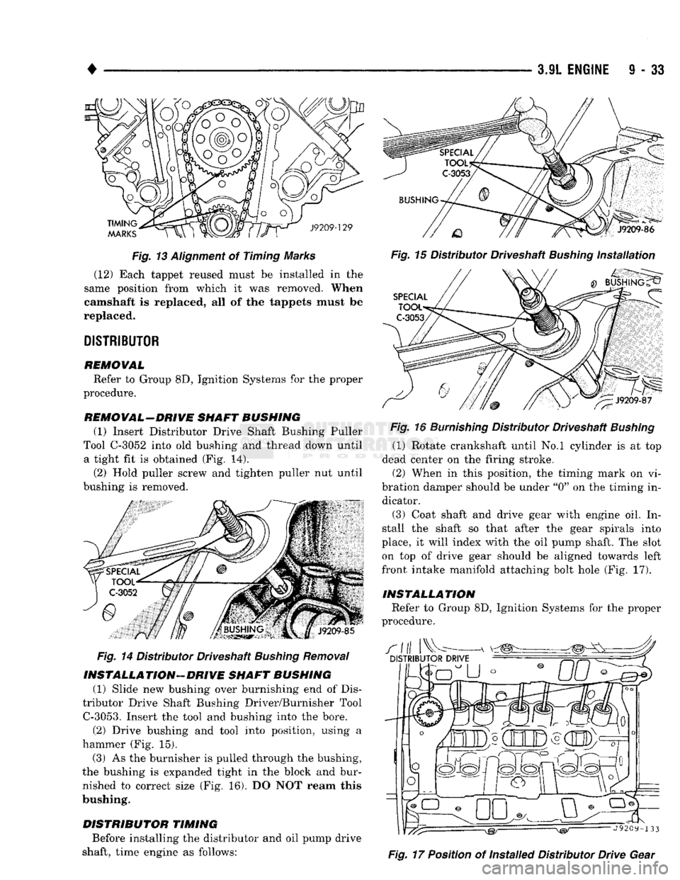
Fig. 13 Alignment of Timing Marks (12) Each tappet reused must be installed in the
same position from which it was removed.
When
camshaft
Is replaced, all of the tappets must be
replaced.
DISTRIBUTOR
REMOVAL
Refer to Group 8D, Ignition Systems for the proper
procedure.
REMOVAL-DRIVE SHAFT BUSHING (1)
Insert Distributor Drive Shaft Bushing Puller
Tool C-3052 into old bushing and thread down until a tight fit is obtained (Fig. 14).
(2)
Hold puller screw and tighten puller nut until
bushing is removed.
Fig.
14 Distributor Driveshaft Bushing Removal
INSTALLATION-DRIVE
SHAFT BUSHING (1) Slide new bushing over burnishing end of Dis
tributor Drive Shaft Bushing Driver/Burnisher Tool
C-3053.
Insert the tool and bushing into the bore. (2) Drive bushing and tool into position, using a
hammer (Fig. 15).
(3) As the burnisher is pulled through the bushing,
the bushing is expanded tight in the block and bur nished to correct size (Fig. 16). DO NOT ream this
bushing.
DISTRIBUTOR
TIMING
Before installing the distributor and oil pump drive
shaft, time engine as follows:
Fig.
16
Burnishing
Distributor Driveshaft
Bushing
(1) Rotate crankshaft until No.l cylinder is at top
dead center on the firing stroke. (2) When in this position, the timing mark on vi
bration damper should be under "0" on the timing in dicator.
(3) Coat shaft and drive gear with engine oil. In
stall the shaft so that after the gear spirals into
place, it will index with the oil pump shaft. The slot on top of drive gear should be aligned towards left
front intake manifold attaching bolt hole (Fig. 17).
INSTALLATION
Refer to Group 8D, Ignition Systems for the proper
procedure.
Fig.
17 Position of Installed Distributor Drive Gear
Page 659 of 1502
FLANGE GASKET
X
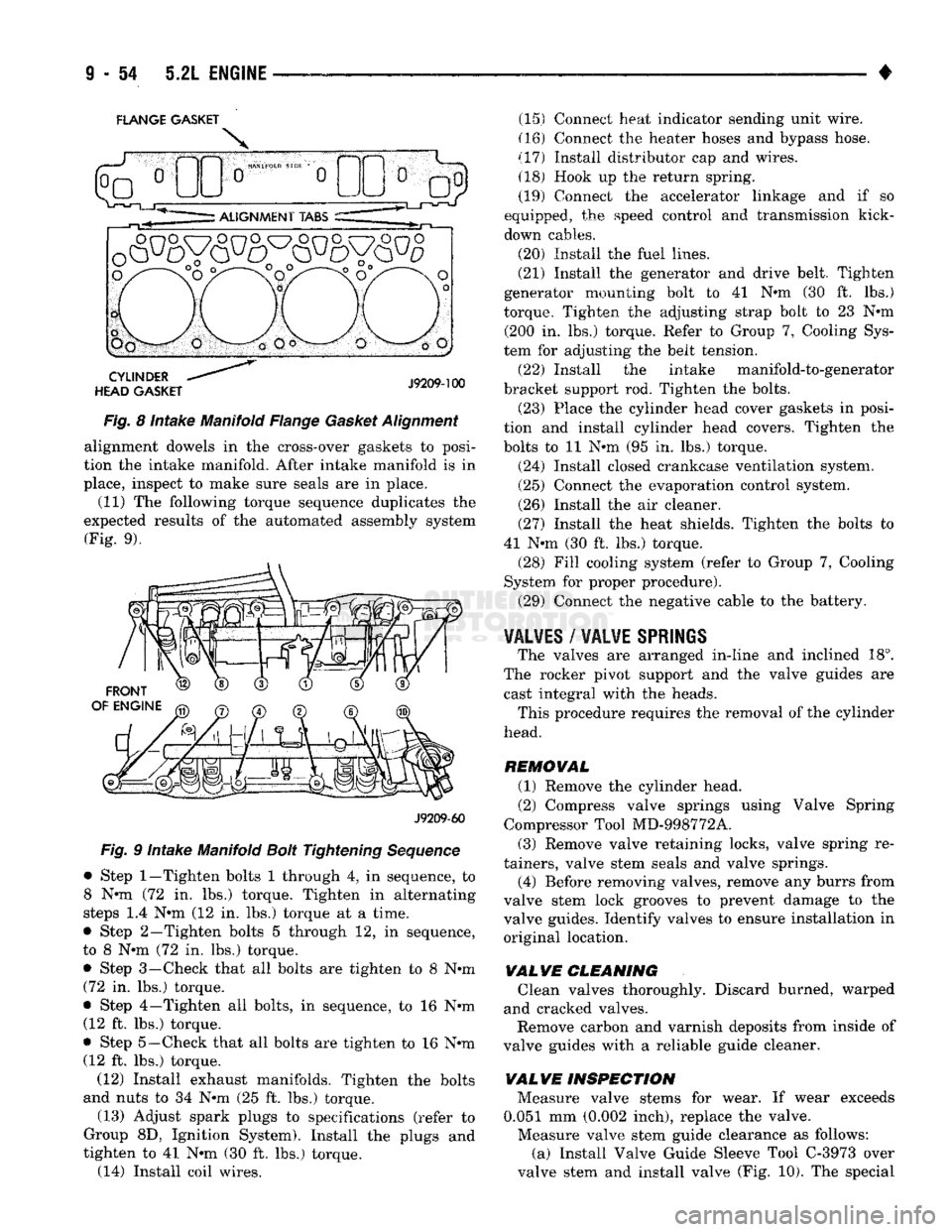
Fig. 8 intake Manifold Flange Gasket Alignment alignment dowels in the cross-over gaskets to posi
tion the intake manifold. After intake manifold is in
place, inspect to make sure seals are in place. (11) The following torque sequence duplicates the
expected results of the automated assembly system (Fig. 9).
J9209-60
Fig. 9 Intake Manifold Bolt Tightening Sequence
• Step
1—Tighten
bolts 1 through 4, in sequence, to
8 N-m (72 in. lbs.) torque. Tighten in alternating
steps 1.4 N-m (12 in. lbs.) torque at a time.
• Step 2—Tighten bolts 5 through 12, in sequence,
to 8 N-m (72 in. lbs.) torque.
• Step 3—Check that all bolts are tighten to 8 N-m (72 in. lbs.) torque.
• Step 4—Tighten all bolts, in sequence, to 16 N-m (12 ft. lbs.) torque.
• Step
5—Check
that all bolts are tighten to 16 N-m (12 ft. lbs.) torque.
(12) Install exhaust manifolds. Tighten the bolts
and nuts to 34 N-m (25 ft. lbs.) torque.
(13) Adjust spark plugs to specifications (refer to
Group 8D, Ignition System). Install the plugs and
tighten to 41 N-m (30 ft. lbs.) torque. (14) Install coil wires. (15) Connect heat indicator sending unit wire.
(16) Connect the heater hoses and bypass hose.
(17) Install distributor cap and wires. (18) Hook up the return spring.
(19) Connect the accelerator linkage and if so
equipped, the speed control and transmission kick-
down cables.
(20) Install the fuel lines.
(21) Install the generator and drive belt. Tighten
generator mounting bolt to 41 N-m (30 ft. lbs.)
torque. Tighten the adjusting strap bolt to 23 N-m (200 in. lbs.) torque. Refer to Group 7, Cooling Sys
tem for adjusting the belt tension.
(22) Install the intake manifold-to-generator
bracket support rod. Tighten the bolts. (23) Place the cylinder head cover gaskets in posi
tion and install cylinder head covers. Tighten the
bolts to 11 N-m (95 in. lbs.) torque.
(24) Install closed crankcase ventilation system.
(25) Connect the evaporation control system.
(26) Install the air cleaner.
(27) Install the heat shields. Tighten the bolts to
41 N-m (30 ft. lbs.) torque. (28) Fill cooling system (refer to Group 7, Cooling
System for proper procedure).
(29) Connect the negative cable to the battery.
VALVES
/
VALVE
SPRINGS
The valves are arranged in-line and inclined 18°.
The rocker pivot support and the valve guides are cast integral with the heads. This procedure requires the removal of the cylinder
head.
REMOVAL (1) Remove the cylinder head.
(2) Compress valve springs using Valve Spring
Compressor Tool MD-998772A.
(3) Remove valve retaining locks, valve spring re
tainers, valve stem seals and valve springs.
(4) Before removing valves, remove any burrs from
valve stem lock grooves to prevent damage to the
valve guides. Identify valves to ensure installation in
original location.
VALVE CLEANING Clean valves thoroughly. Discard burned, warped
and cracked valves. Remove carbon and varnish deposits from inside of
valve guides with a reliable guide cleaner.
VAL VE INSPECTION Measure valve stems for wear. If wear exceeds
0.051 mm (0.002 inch), replace the valve. Measure valve stem guide clearance as follows:
(a) Install Valve Guide Sleeve Tool C-3973 over
valve stem and install valve (Fig. 10). The special