1993 DODGE TRUCK ignition
[x] Cancel search: ignitionPage 667 of 1502
9 - 62 5.2L
ENGINE
Fig,
11 Camshaft
Bearings
Removal
and
installation
with
Tool C-3132-A
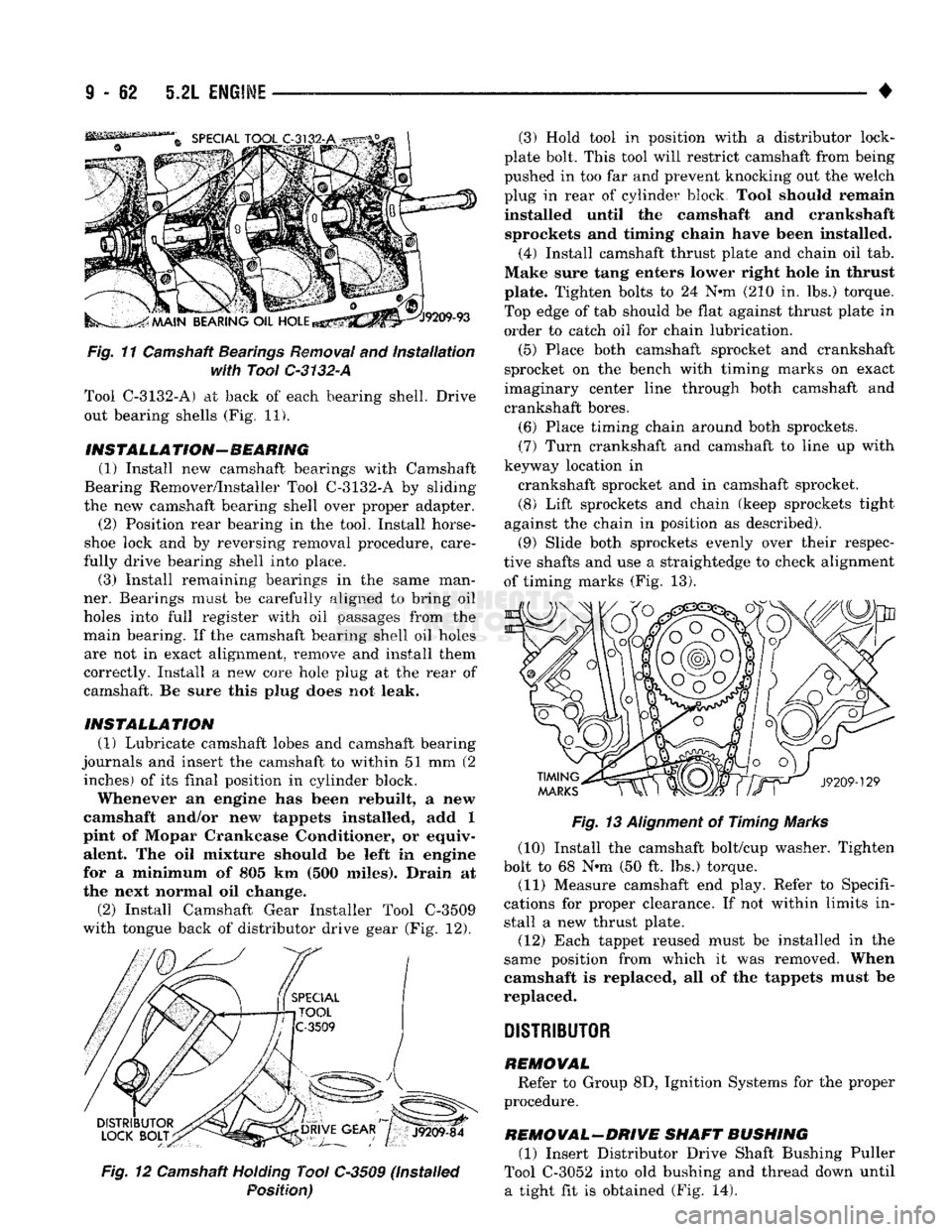
Tool C-3132-A) at back of each bearing shell. Drive out bearing shells (Fig. 11).
INSTALL A
TION-
BEARING
(1) Install new camshaft bearings with Camshaft
Bearing Remover/Installer Tool C-3132-A by sliding
the new camshaft bearing shell over proper adapter. (2) Position rear bearing in the tool. Install horse
shoe lock and by reversing removal procedure, care
fully drive bearing shell into place. (3) Install remaining bearings in the same man
ner. Bearings must be carefully aligned to bring oil
holes into full register with oil passages from the
main bearing. If the camshaft bearing shell oil holes are not in exact alignment, remove and install them
correctly. Install a new core hole plug at the rear of
camshaft. Be sure this plug does not leak.
INSTALLATION
(1) Lubricate camshaft lobes and camshaft bearing
journals and insert the camshaft to within 51 mm (2 inches) of its final position in cylinder block.
Whenever an engine has been rebuilt, a new
camshaft and/or new tappets installed, add 1
pint of Mopar Crankcase Conditioner, or equiv alent. The oil mixture should be left in engine
for a minimum of 805 km (500 miles). Drain at
the next normal oil change.
(2) Install Camshaft Gear Installer Tool C-3509
with tongue back of distributor drive gear (Fig. 12).
Fig.
12 Camshaft
Holding
Tool C-3509 (Installed
Position)
• — —— — — •
Fig.
13
Alignment
of Timing Marks
(10) Install the camshaft bolt/cup washer. Tighten
bolt to 68 N«m (50 ft. lbs.) torque. (11) Measure camshaft end play. Refer to Specifi
cations for proper clearance. If not within limits in stall a new thrust plate.
(12) Each tappet reused must be installed in the
same position from which it was removed. When
camshaft is replaced, all of the tappets must be
replaced.
DISTRIBUTOR
REMOVAL
Refer to Group 8D, Ignition Systems for the proper
procedure.
REMOVAL-DRIVE SHAFT BUSHING
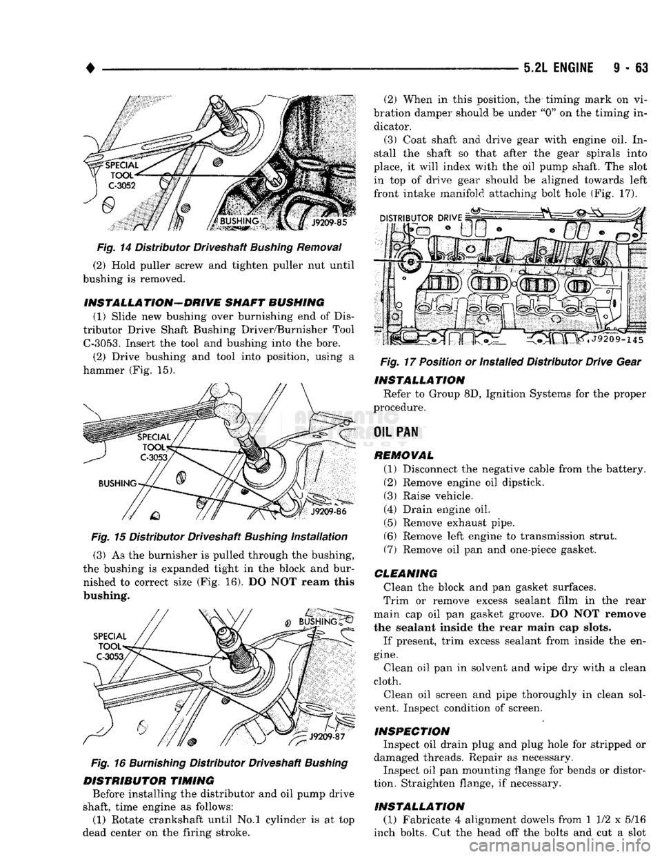
(1) Insert Distributor Drive Shaft Bushing Puller
Tool C-3052 into old bushing and thread down until a tight fit is obtained (Fig. 14). (3) Hold tool in position with a distributor lock-
plate bolt. This tool will restrict camshaft from being
pushed in too far and prevent knocking out the welch
plug in rear of cylinder block Tool should remain installed until the camshaft and crankshaft sprockets and timing chain have been installed.
(4)
Install camshaft thrust plate and chain oil tab.
Make sure tang enters lower right hole in thrust plate. Tighten bolts to 24 N*m (210 in. lbs.) torque.
Top edge of tab should be flat against thrust plate in
order to catch oil for chain lubrication.
(5) Place both camshaft sprocket and crankshaft
sprocket on the bench with timing marks on exact
imaginary center line through both camshaft and crankshaft bores.
(6) Place timing chain around both sprockets. (7) Turn crankshaft and camshaft to line up with
keyway location in crankshaft sprocket and in camshaft sprocket.
(8) Lift sprockets and chain (keep sprockets tight
against the chain in position as described). (9) Slide both sprockets evenly over their respec
tive shafts and use a straightedge to check alignment of timing marks (Fig. 13).
Page 668 of 1502
•
5.2L
ENGINE
I - 63
Fig.
14 Distributor Driveshaft
Bushing
Removal
(2) Hold puller screw and tighten puller nut until
bushing is removed.
INSTALLA TION-DRIVE
SHAFT BUSHING
(1) Slide new bushing over burnishing end of Dis
tributor Drive Shaft Bushing Driver/Burnisher Tool
C-3053.
Insert the tool and bushing into the bore. (2) Drive bushing and tool into position, using a
hammer (Fig. 15).
Fig. 15 Distributor Driveshaft Bushing Installation (3) As the burnisher is pulled through the bushing,
the bushing is expanded tight in the block and bur nished to correct size (Fig. 16). DO NOT ream this
bushing.
Fig.
16
Burnishing
Distributor Driveshaft
Bushing
DISTRIBUTOR TIMING Before installing the distributor and oil pump drive
shaft, time engine as follows:
(1) Rotate crankshaft until No.l cylinder is at top
dead center on the firing stroke. (2) When in this position, the timing mark on vi
bration damper should be under "0" on the timing in dicator.
(3) Coat shaft and drive gear with engine oil. In
stall the shaft so that after the gear spirals into
place, it will index with the oil pump shaft. The slot in top of drive gear should be aligned towards left
front intake manifold attaching bolt hole (Fig. 17).
Fig.
17 Position or Installed Distributor Drive Gear
INSTALLATION Refer to Group 8D, Ignition Systems for the proper
procedure.
OIL
PAN REMOVAL (1) Disconnect the negative cable from the battery.
(2) Remove engine oil dipstick. (3) Raise vehicle.
(4) Drain engine oil. (5) Remove exhaust pipe.
(6) Remove left engine to transmission strut.
(7) Remove oil pan and one-piece gasket.
CLEANING Clean the block and pan gasket surfaces.
Trim or remove excess sealant film in the rear
main cap oil pan gasket groove. DO NOT remove
the sealant inside the rear main cap slots.
If present, trim excess sealant from inside the en
gine.
Clean oil pan in solvent and wipe dry with a clean
cloth.
Clean oil screen and pipe thoroughly in clean sol
vent. Inspect condition of screen.
INSPECTION Inspect oil drain plug and plug hole for stripped or
damaged threads. Repair as necessary.
Inspect oil pan mounting flange for bends or distor
tion. Straighten flange, if necessary.
INSTALLATION (1) Fabricate 4 alignment dowels from 1 1/2 x 5/16
inch bolts. Cut the head off the bolts and cut a slot
Page 689 of 1502
FLANGE GASKET
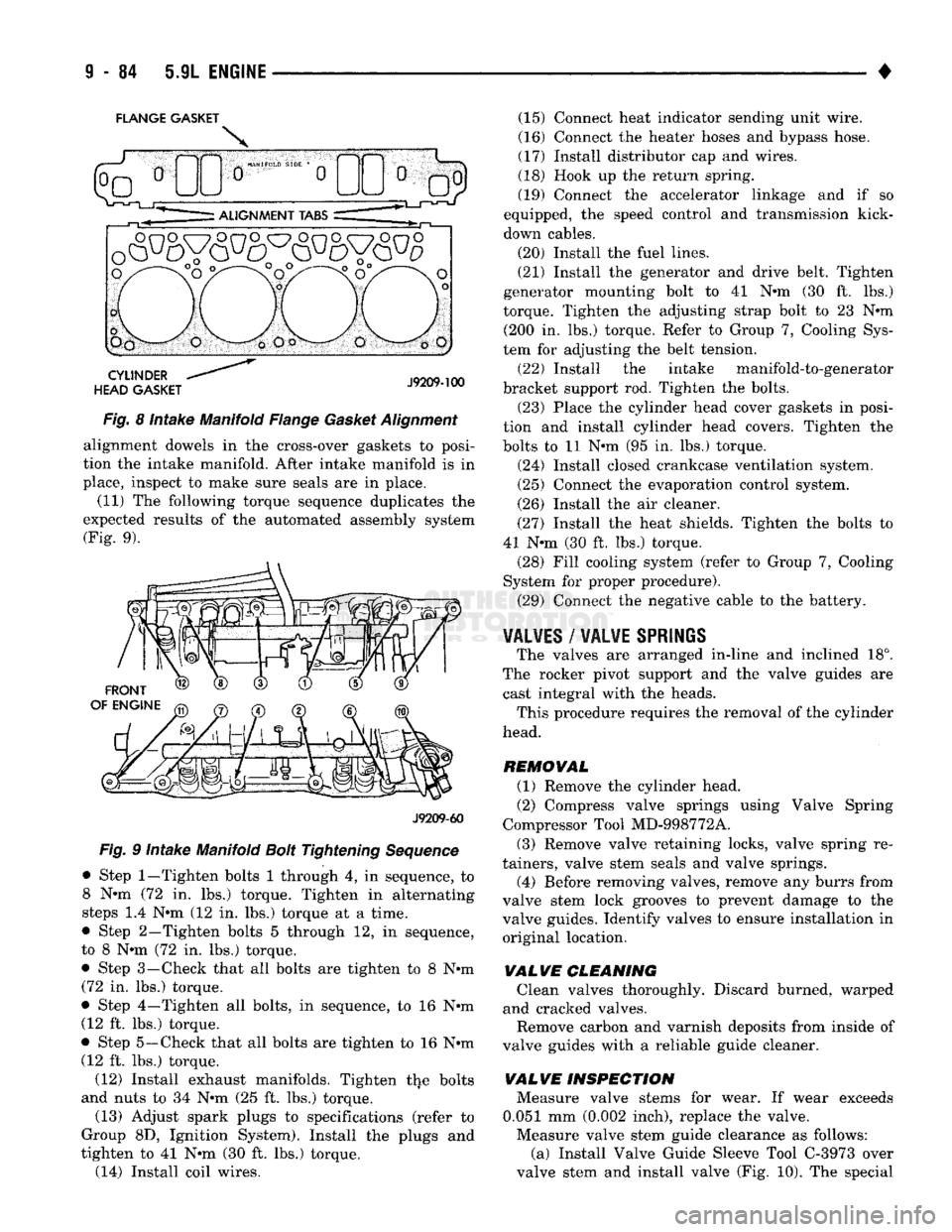
Fig. 8 Intake Manifold Flange Gasket Alignment alignment dowels in the cross-over gaskets to posi
tion the intake manifold. After intake manifold is in
place, inspect to make sure seals are in place.
(11) The following torque sequence duplicates the
expected results of the automated assembly system (Fig. 9).
J9209-60
Fig. 9 Intake Manifold Bolt Tightening Sequence
• Step
1—Tighten
bolts 1 through 4, in sequence, to 8 N-m (72 in. lbs.) torque. Tighten in alternating
steps 1.4 N-m (12 in. lbs.) torque at a time.
• Step 2—Tighten bolts 5 through 12, in sequence,
to 8 N-m (72 in. lbs.) torque. • Step 3—-Check that all bolts are tighten to 8 N-m
(72 in. lbs.) torque.
• Step 4—Tighten all bolts, in sequence, to 16 N-m (12 ft. lbs.) torque.
• Step 5—Check that all bolts are tighten to 16 N-m (12 ft. lbs.) torque.
(12) Install exhaust manifolds. Tighten the bolts
and nuts to 34 N-m (25 ft. lbs.) torque.
(13) Adjust spark plugs to specifications (refer to
Group 8D, Ignition System). Install the plugs and
tighten to 41 N-m (30 ft. lbs.) torque. (14) Install coil wires. (15) Connect heat indicator sending unit wire.
(16) Connect the heater hoses and bypass hose.
(17) Install distributor cap and wires.
(18) Hook up the return spring.
(19) Connect the accelerator linkage and if so
equipped, the speed control and transmission kick-
down cables.
(20) Install the fuel lines.
(21) Install the generator and drive belt. Tighten
generator mounting bolt to 41 N-m (30 ft. lbs.)
torque. Tighten the adjusting strap bolt to 23 N-m (200 In. lbs.) torque. Refer to Group 7, Cooling Sys
tem for adjusting the belt tension.
(22) Install the intake manifold-to-generator
bracket support rod. Tighten the bolts.
(23) Place the cylinder head cover gaskets in posi
tion and install cylinder head covers. Tighten the
bolts to 11 N-m (95 in. lbs.) torque.
(24) Install closed crankcase ventilation system.
(25) Connect the evaporation control system.
(26) Install the air cleaner.
(27) Install the heat shields. Tighten the bolts to
41 N-m (30 ft. lbs.) torque. (28) Fill cooling system (refer to Group 7, Cooling
System for proper procedure).
(29) Connect the negative cable to the battery.
¥AL¥ES
/
WALWE SPRIliS
The valves are arranged in-line and inclined 18°.
The rocker pivot support and the valve guides are cast integral with the heads. This procedure requires the removal of the cylinder
head.
REMOVAL (1) Remove the cylinder head.
(2) Compress valve springs using Valve Spring
Compressor Tool MD-998772A.
(3) Remove valve retaining locks, valve spring re
tainers, valve stem seals and valve springs.
(4) Before removing valves, remove any burrs from
valve stem lock grooves to prevent damage to the
valve guides. Identify valves to ensure Installation in original location,
VALVE
CLEANING Clean valves thoroughly. Discard burned, warped
and cracked valves.
Remove carbon and varnish deposits from Inside of
valve guides with a reliable guide cleaner.
VALVE
INSPECTION Measure valve stems for wear. If wear exceeds
0.051 mm (0.002 Inch), replace the valve.
Measure valve stem guide clearance as follows: (a) Install Valve Guide Sleeve Tool C-3973 over
valve stem and install valve (Fig. 10). The special
Page 697 of 1502
9
- 92 5.9L
ENGINE
•
Fig.
11 Camshaft
Bearings
Removal
and
Installation
with Tool
C-3132-A
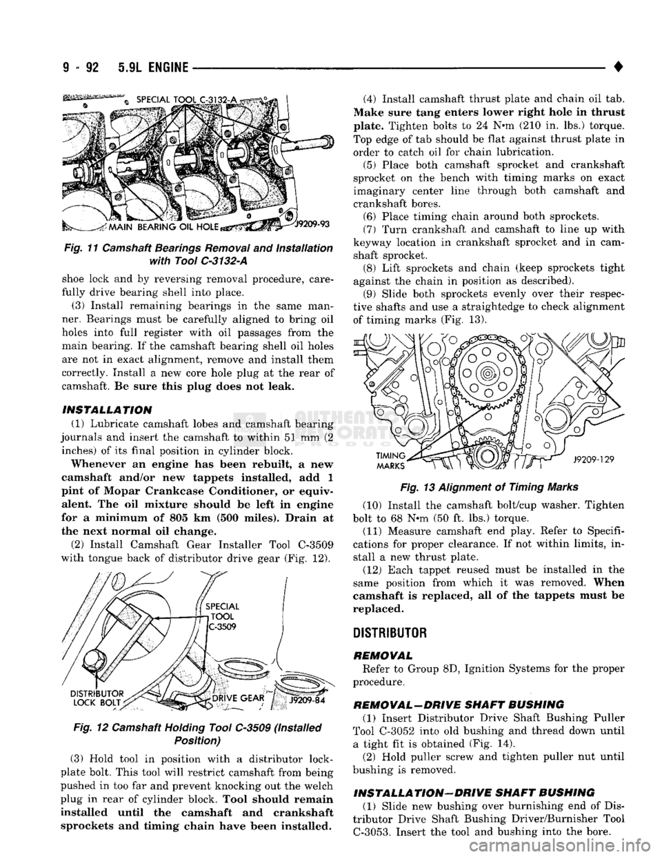
shoe lock and by reversing removal procedure, care
fully drive bearing shell into place. (3) Install remaining bearings in the same man
ner. Bearings must be carefully aligned to bring oil
holes into full register with oil passages from the main bearing. If the camshaft bearing shell oil holes
are not in exact alignment, remove and install them
correctly. Install a new core hole plug at the rear of
camshaft. Be sure this plug does not leak.
INSTALLATION (1) Lubricate camshaft lobes and camshaft bearing
journals and insert the camshaft to within 51 mm (2 inches) of its final position in cylinder block.
Whenever an engine has been rebuilt, a new
camshaft and/or new tappets installed, add 1
pint of Mopar Crankcase Conditioner, or equiv alent. The oil mixture should be left in engine
for a minimum of 805 km (500 miles). Drain at
the next normal oil change.
(2)
Install Camshaft Gear Installer Tool C-3509
with tongue back of distributor drive gear (Fig. 12).
Fig.
12 Camshaft
Holding
Tool C-3509 (Installed
Position)
(3) Hold tool in position with a distributor lock-
plate bolt. This tool will restrict camshaft from being
pushed in too far and prevent knocking out the welch
plug in rear of cylinder block. Tool should remain
installed until the camshaft and crankshaft sprockets and timing chain have been installed. (4) Install camshaft thrust plate and chain oil tab.
Make sure tang enters lower right hole in thrust
plate. Tighten bolts to 24 N-m (210 in. lbs.) torque.
Top edge of tab should be flat against thrust plate in
order to catch oil for chain lubrication.
(5) Place both camshaft sprocket and crankshaft
sprocket on the bench with timing marks on exact
imaginary center line through both camshaft and
crankshaft bores. (6) Place timing chain around both sprockets.
(7) Turn crankshaft and camshaft to line up with
keyway location in crankshaft sprocket and in cam shaft sprocket. (8) Lift sprockets and chain (keep sprockets tight
against the chain in position as described). (9) Slide both sprockets evenly over their respec
tive shafts and use a straightedge to check alignment of timing marks (Fig. 13).
Fig.
13
Alignment
of Timing Marks
(10) Install the camshaft bolt/cup washer. Tighten
bolt to 68 N-m (50 ft. lbs.) torque.
(11) Measure camshaft end play. Refer to Specifi
cations for proper clearance. If not within limits, in stall a new thrust plate.
(12) Each tappet reused must be installed in the
same position from which it was removed. When
camshaft is replaced, all of the tappets must be
replaced.
DISTRIBUTOR
REMOVAL Refer to Group 8D, Ignition Systems for the proper
procedure.
REMOVAL-DRIVE SHAFT BUSHING (1) Insert Distributor Drive Shaft Bushing Puller
Tool C-3052 into old bushing and thread down until a tight fit is obtained (Fig. 14).
(2) Hold puller screw and tighten puller nut until
bushing is removed.
INSTALLATION-DRIVE SHAFT BUSHING (1) Slide new bushing over burnishing end of Dis
tributor Drive Shaft Bushing Driver/Burnisher Tool
C-3053.
Insert the tool and bushing into the bore.
Page 698 of 1502
•
5.9L
ENGINE
9 - 93
Fig.
14
Removing
Distributor Driveshaft
Bushing
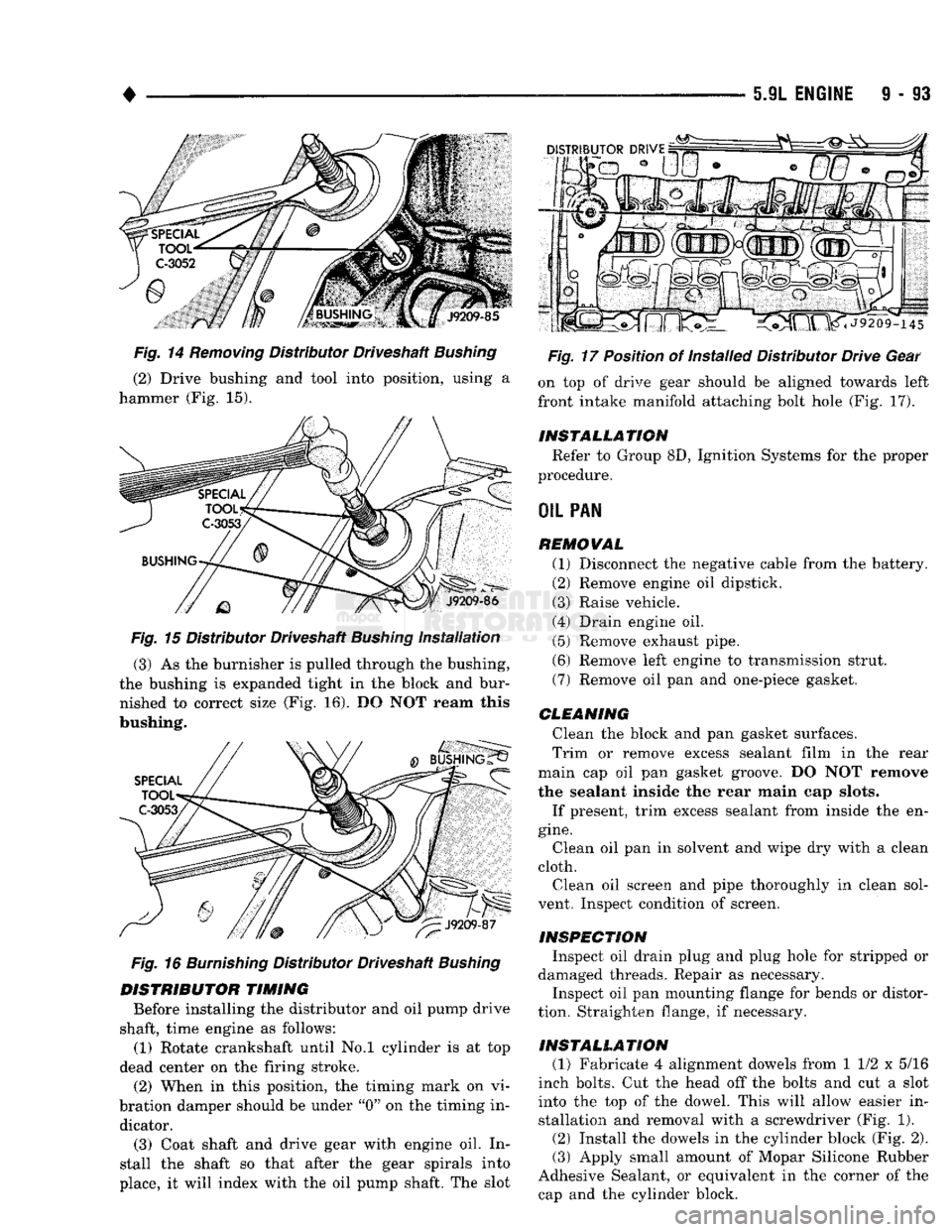
(2) Drive bushing and tool into position, using a
hammer (Fig. 15).
Fig.
15 Distributor Driveshaft
Bushing
Installation
(3) As the burnisher is pulled through the bushing,
the bushing is expanded tight in the block and bur nished to correct size (Fig. 16). DO NOT ream this
bushing.
Fig.
16
Burnishing
Distributor Driveshaft
Bushing
DISTRIBUTOR
TIMING
Before installing the distributor and oil pump drive
shaft, time engine as follows: (1) Rotate crankshaft until No.l cylinder is at top
dead center on the firing stroke. (2) When in this position, the timing mark on vi
bration damper should be under "0" on the timing in dicator.
(3) Coat shaft and drive gear with engine oil. In
stall the shaft so that after the gear spirals into
place, it will index with the oil pump shaft. The slot
Fig.
17 Position of Installed Distributor Drive Gear
on top of drive gear should be aligned towards left
front intake manifold attaching bolt hole (Fig. 17).
INSTALLATION
Refer to Group 8D, Ignition Systems for the proper
procedure.
OIL
PAN
REMOVAL
(1) Disconnect the negative cable from the battery.
(2) Remove engine oil dipstick.
(3) Raise vehicle.
(4) Drain engine oil. (5) Remove exhaust pipe.
(6) Remove left engine to transmission strut.
(7) Remove oil pan and one-piece gasket.
CLEANING
Clean the block and pan gasket surfaces.
Trim or remove excess sealant film in the rear
main cap oil pan gasket groove. DO NOT remove
the sealant inside the rear main cap slots.
If present, trim excess sealant from inside the en
gine.
Clean oil pan in solvent and wipe dry with a clean
cloth. Clean oil screen and pipe thoroughly in clean sol
vent. Inspect condition of screen.
INSPECTION
Inspect oil drain plug and plug hole for stripped or
damaged threads. Repair as necessary.
Inspect oil pan mounting flange for bends or distor
tion. Straighten flange, if necessary.
INSTALLATION
(1) Fabricate 4 alignment dowels from 1 1/2 x 5/16
inch bolts. Cut the head off the bolts and cut a slot into the top of the dowel. This will allow easier installation and removal with a screwdriver (Fig. 1).
(2) Install the dowels in the cylinder block (Fig. 2). (3) Apply small amount of Mopar Silicone Rubber
Adhesive Sealant, or equivalent in the corner of the cap and the cylinder block.
Page 792 of 1502
FRAME
AND
BUMPERS
13 -
TAN-
BLACK*
-o
ORANGE
WITH
WHITE
TRACER
SWITCH
I
RAISE
| AND j
!
LOWER
x
RED-
6 o
SWITCH
O
IGNITION SWITCH
ANGLE
TAN
LIGHT
'GREEN
ORANGE
WITH
WHITE
TRACER
FUSE
»
+
BATTERY
•o
SOLENOID SWITCH
•
MOTOR
ENERGIZED:
MOTOR
AND "B"
COIL
PRESSURE
RELIEF
"B"
SOLENOID
JUL.
'C"
SOLENOID
ANGLING CYLINDER
CSSE]
OPERATING
PRESSURE
EXHAUST
INTAKE
OR
DRAIN
METERED
FLOW
RB525
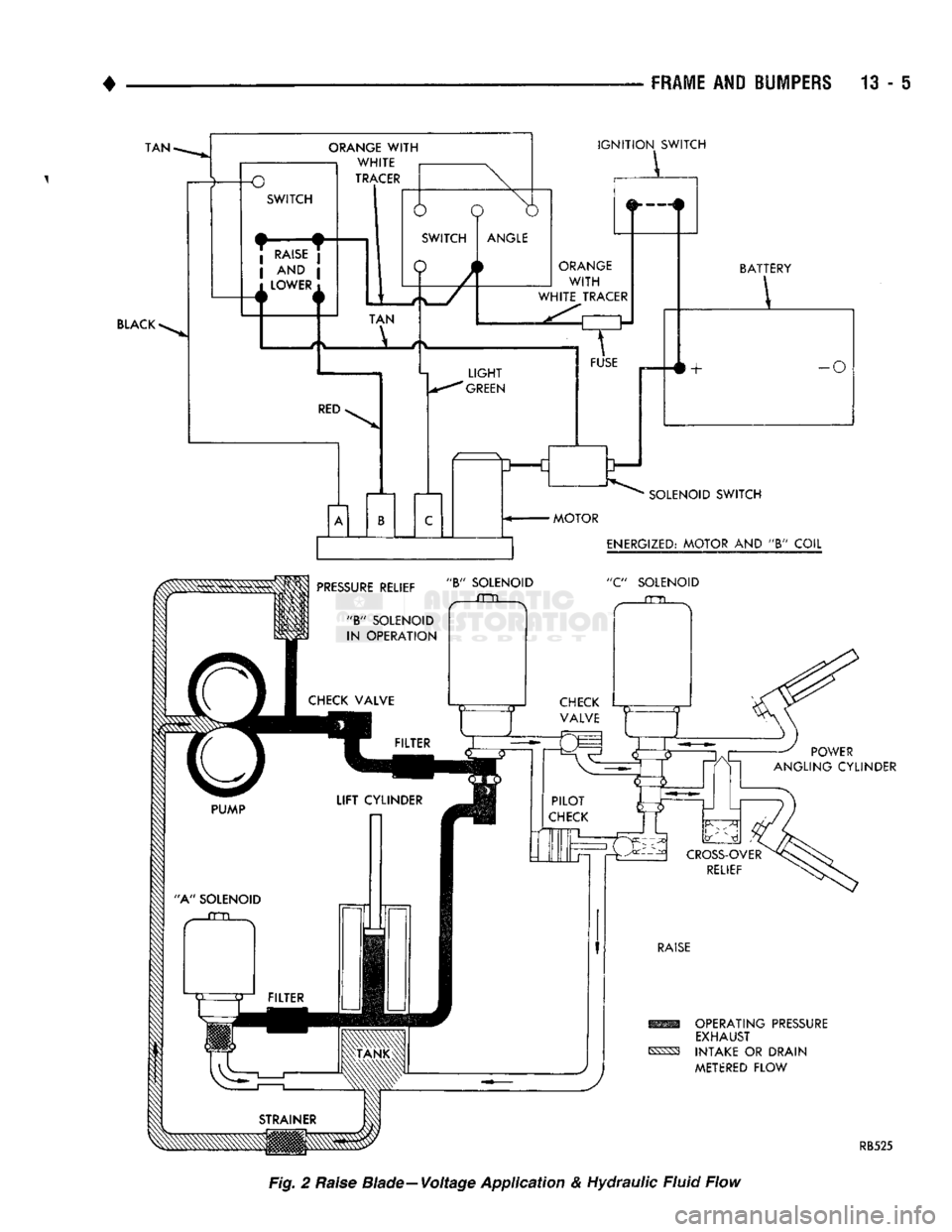
Fig.
2 Raise Blade—Voltage Application & Hydraulic Fluid Flow
Page 793 of 1502
- 6 FRAME AND BUMPERS
•
SWITCH TAN
ORANGE
WITH
WHITE
TRACER
RED
N 6
o IGNITION SWITCH
_L_
ANGLE
ORANGE
WITH
WHITE TRACER L f
FUSE
LIGHT GREEN
u==c
SOLENOID SWITCH >+
BATTERY
•o
ENERGIZED:
"A" COIL C" SOLENOID
POWER
ANGLING CYLINDER
LOWER AND FLOAT
(FORCE APPLIED AGAINST
LIFT
RAM)
OPERATING
PRESSURE
EXHAUST
INTAKE OR DRAIN
METERED
FLOW
RB526
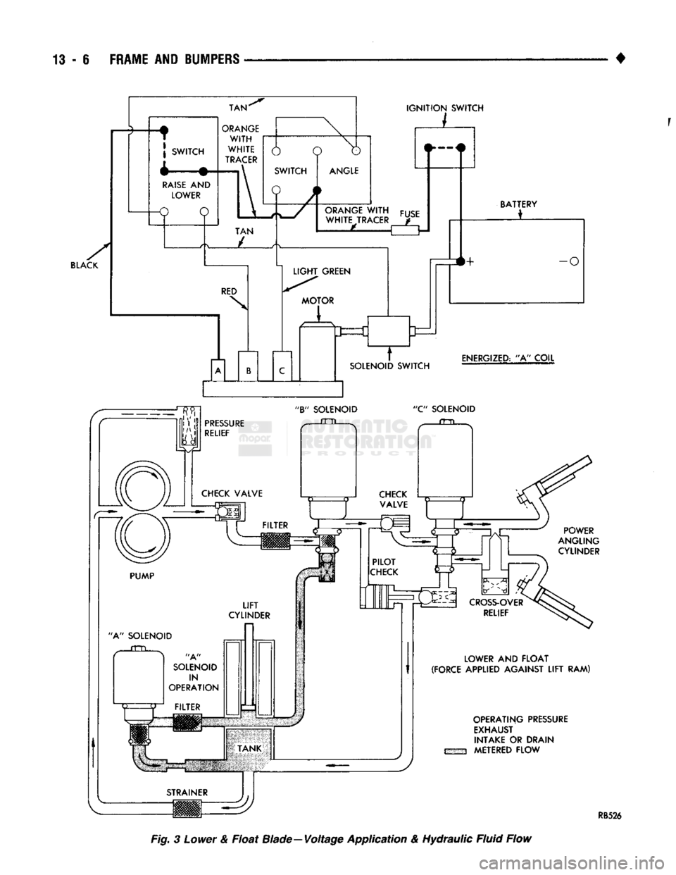
Fig. 3
Lower
&
Float
Blade—Voltage
Application
&
Hydraulic
Fluid
Flow
Page 794 of 1502
FRAME
AND
BUMPERS
13 - 7
IGNITION
SWITCH
L
BLACK
mm OPERATING PRESSURE EXHAUST
^SS3 INTAKE OR
DRAIN
METERED
FLOW
RB527
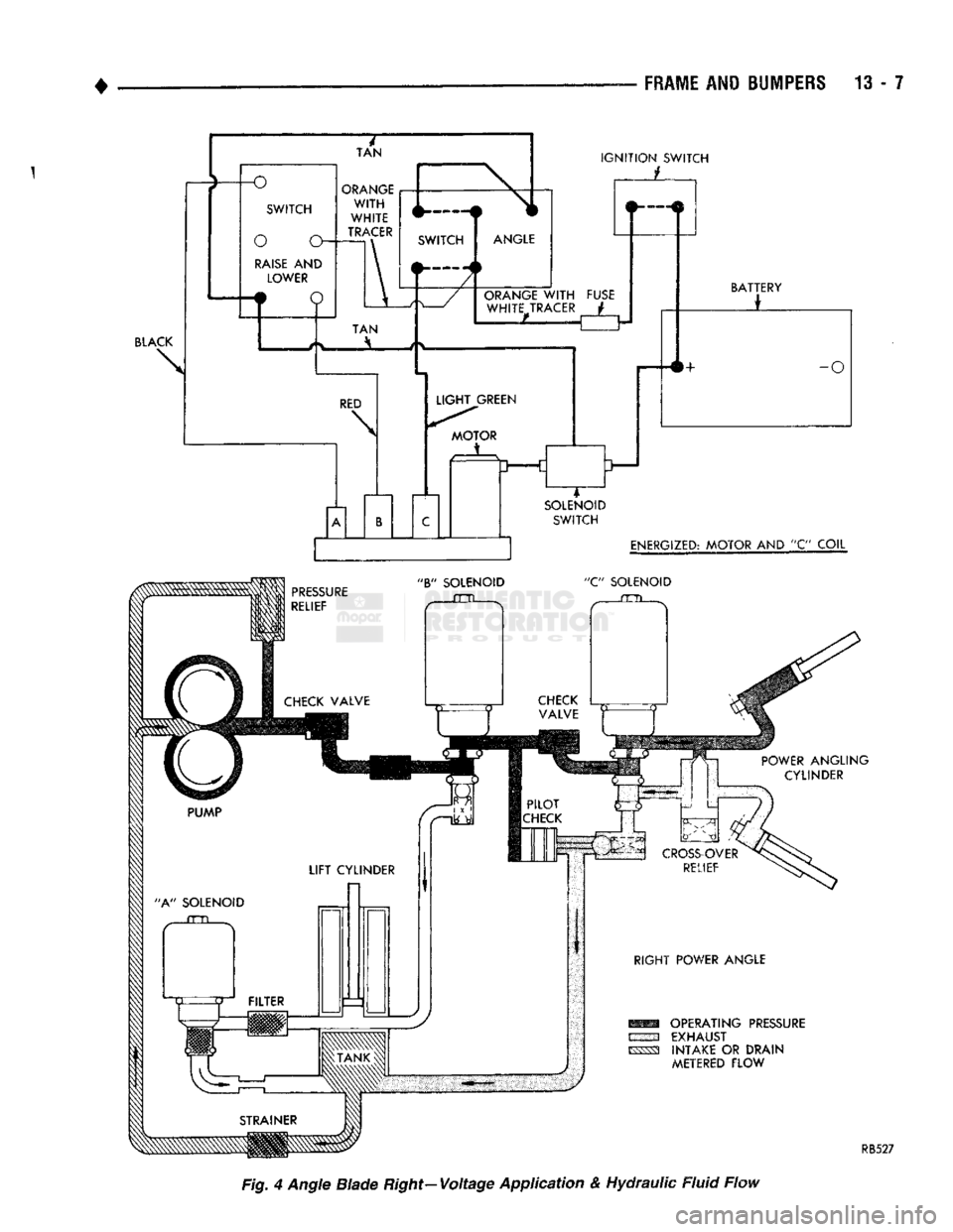
Fig, 4 Angle Blade Right-Voltage Application & Hydraulic Fluid Flow