1993 DODGE TRUCK ignition
[x] Cancel search: ignitionPage 913 of 1502
14
- 94
FUEL
SYSTEM
•
THROTTLE POSITION
SENSOR
TEST
CAUTION;
Before checking
the
TPS,
the
throttle
linkage must
be
checked
for
correct
adjustment.
The
throttle
lever must
contact
the low idle
speed screw.
The
throttle
lever must reach breakover when
the
throttle
is
wide
open. Refer
to the
Accelerator Pedal and
Throttle
Cable section
of
Group
14,
Fuel Systems.
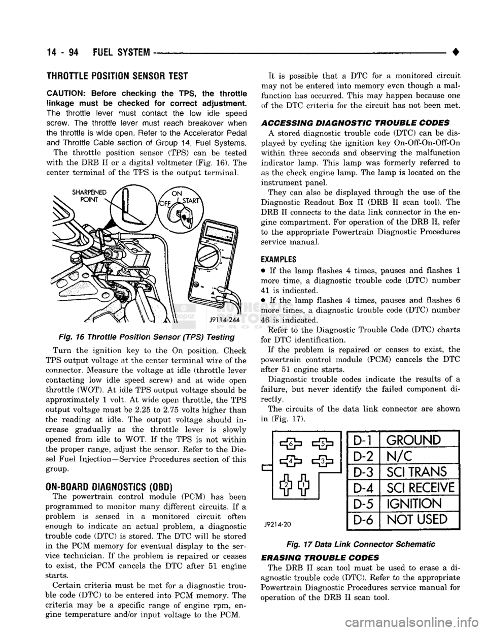
The throttle position sensor (TPS) can be tested
with the DRB II or a digital voltmeter (Fig. 16). The center terminal of the TPS is the output terminal.
J9114-244
Fig.
16
Throttle
Position
Sensor
(TPS) Testing
Turn the ignition key to the On position. Check
TPS output voltage at the center terminal wire of the connector. Measure the voltage at idle (throttle lever contacting low idle speed screw) and at wide open
throttle
(WOT).
At idle TPS output voltage should be approximately 1 volt. At wide open throttle, the TPS
output voltage must be 2.25 to 2.75 volts higher than
the reading at idle. The output voltage should in
crease gradually as the throttle lever is slowly
opened from idle to WOT. If the TPS is not within
the proper range, adjust the sensor. Refer to the Die sel Fuel Injection—Service Procedures section of this
group.
ON-BOARD
DIAGNOSTICS
(OBD) The powertrain control module (PCM) has been
programmed to monitor many different circuits. If a
problem is sensed in a monitored circuit often enough to indicate an actual problem, a diagnostic
trouble code (DTC) is stored. The DTC will be stored in the PCM memory for eventual display to the ser
vice technician. If the problem is repaired or ceases
to exist, the PCM cancels the DTC after 51 engine
starts.
Certain criteria must be met for a diagnostic trou
ble code (DTC) to be entered into PCM memory. The criteria may be a specific range of engine rpm, engine temperature and/or input voltage to the PCM. It is possible that a DTC for a monitored circuit
may not be entered into memory even though a mal
function has occurred. This may happen because one of the DTC criteria for the circuit has not been met.
ACCESSING DIAGNOSTIC TROUBLE CODES A stored diagnostic trouble code (DTC) can be dis
played by cycling the ignition key On-Off-On-Off-On
within three seconds and observing the malfunction indicator lamp. This lamp was formerly referred to
as the check engine lamp. The lamp is located on the
instrument panel.
They can also be displayed through the use of the
Diagnostic Readout Box II (DRB II scan tool). The
DRB II connects to the data link connector in the en
gine compartment. For operation of the DRB II, refer
to the appropriate Powertrain Diagnostic Procedures service manual.
EXAMPLES
• If the lamp flashes 4 times, pauses and flashes 1
more time, a diagnostic trouble code (DTC) number
41 is indicated.
• If the lamp flashes 4 times, pauses and flashes 6
more times, a diagnostic trouble code (DTC) number 46 is indicated. Refet* to the Diagnostic Trouble Code (DTC) charts
for DTC identification. If the problem is repaired or ceases to exist, the
powertrain control module (PCM) cancels the DTC after 51 engine starts.
Diagnostic trouble codes indicate the results of a
failure, but never identify the failed component di
rectly.
The circuits of the data link connector are shown
in (Fig. 17).
J9214-20
D-1
1
GROUND
D-2
N/C
D-3
SCI
TRANS
D-4
SCI
RECEIVE
D-5 IGNITION
D-6
NOT USED
Fig.
17
Data
Link
Connector
Schematic
ERASING TROUBLE CODES The DRB II scan tool must be used to erase a di
agnostic trouble code (DTC). Refer to the appropriate
Powertrain Diagnostic Procedures service manual for
operation of the DRB II scan tool.
Page 918 of 1502
CAV
WIRE
COLOR DESCRIPTION
CAV
WIRE
COLOR DESCRIPTION
1 WT/BK
WATER-IN-FUEL SENSOR 37 OVERDRIVE LAMP SIGNAL
2 TN/BK
COOLANT SENSOR (AUTOMATIC TRANSMISSION ONLY) 38
3 RD BATTERY
39
4
BK/LB*
SENSOR RETURN 40
5 BK/WT
SIGNAL GROUND 41
6 VT/WT*
5 VOLT SUPPLY 42
7 TN/YL 8 VOLT INPUT 43 GR/LB TACHOMETER
8 44
9 DB
IGNITION SENSE 45 LG DATA LINK RECIEVE
10 RD/WT*
OVERDRIVE OVERRIDE 46
11 BK/TN POWER GROUND
47 WT/OR* VEHICLE SENSOR
12 BK/TN
POWER GROUND 48 BR/RD* SPEED CONTROL COAST/SET SWITCH
13 49 YL/RD* SPEED CONTROL ON/OFF SWITCH
14 50 WT/LG* SPEED CONTROL RESUME/ACCEL SWITCH
15 OR/BK* HEATER
#2
RELAY 51 DB/YL ASD RELAY
16 YL/BK HEATER #1 RELAY 52
17 53 LG/RD* SPEED CONTROL VENT SOLENOID
18 54 BK/PK* WATER-IN-FUEL LAMP
19 55 OR/LG* OVERDRIVE SOLENOID
20 DG GENERATOR FIELD 56 DG/WT WAIT-TO-START LAMP
21 BK/RD
CHARGE (INTAKE) AIR TEMPERATURE SENSOR 57 DG/OR ASD SENSE
22
OR/DB*
THROTTLE POSITION SENSOR 58
23 59
24 GY/BK
REFERENCE PICKUP 60
25 PK
DATA LINK TRANSMIT WIRE COLOR CODES LB
LIGHT BLUE VT VIOLET
26 BK BLACK LG LIGHT GREEN WT
WHITE
27 BR
A/C CLUTCH REQUEST BR BROWN OR ORANGE
YL YELLOW
28 LG/RD THERMO SWITCH DB DARK BLUE PK PINK *
WITH TRACER
29 WT/PK* BRAKE SWITCH DG DARK GREEN
RD RED
30 BR/YL*
PARK/NEUTRAL SWITCH GY GRAY TN TAN
31 ruin
32 BK/PK*
MALFUNCTION INDICATOR LAMP
n
33 TN/RD*
SPEED CONTROL VACUUM SOLENOID CONNECTOR
J//000OOOOOOO
1 1
HI
173456789
10 J/^"*\
Hi
oooooooooo (1 Oj]
VlX
21
22
23
24
25
26
27
28
29
30
\V~V//
oooooooooo
\
II
12 13
14 15
16 17 18
19 20
\
34 DB/OR
WIDE OPEN THROTTLE (A/C) TERMINAL
J//000OOOOOOO
1 1
HI
173456789
10 J/^"*\
Hi
oooooooooo (1 Oj]
VlX
21
22
23
24
25
26
27
28
29
30
\V~V//
oooooooooo)}
31
32 33 34 35 36 37 38 39 40
1JU
35 SHOWN \\\
41 42 43 44 45 46 47 48 49
SO
1
^m^^
|
oooooooooo
1
1
oooooooooo
J//
36
Li
J9314-185
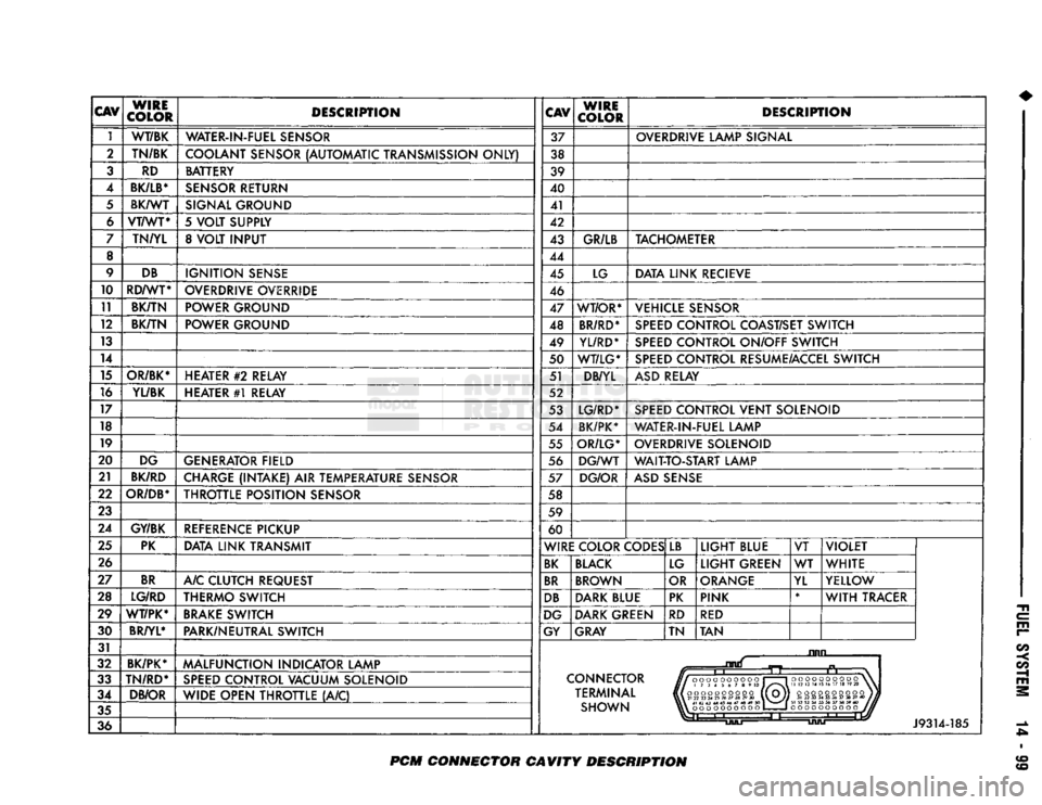
PCM
CONNECTOR CAVITY DESCRIPTION
Page 939 of 1502
14-120
FUEL
SYSTEM
• move the throttle lever (by hand) from the idle posi
tion and lift adapter for removal. Fig. 46
Nylon
Adaptor—TPS to Injector Pump
INSTALLATION
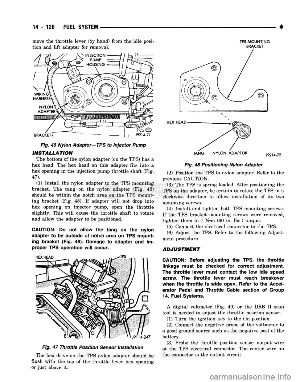
The bottom of the nylon adapter (on the TPS) has a
hex head. The hex head on this adapter fits into a
hex opening in the injection pump throttle shaft (Fig.
47).
(1) Install the nylon adapter to the TPS mounting
bracket. The tang on the nylon adapter (Fig. 48) should be within the notch area on the TPS mount
ing bracket (Fig. 48). If adapter will not drop into
hex opening on injector pump, open the throttle slightly. This will cause the throttle shaft to rotate
and allow the adapter to be positioned.
CAUTION:
Do not allow the tang on the nylon
adapter to be outside of notch area on TPS mount
ing
bracket (Fig. 48).
Damage
to adapter and im
proper TPS operation
will
occur.
Fig.
47
Throttle
Position
Sensor
Installation
The hex drive on the TPS nylon adapter should be
flush with the top of the throttle lever hex opening or just above it.
TPS
MOUNTING
BRACKET
TANG
NYLON
ADAPTOR
Fig. 48 Positioning
Nylon
Adapter (2) Position the TPS to nylon adapter. Refer to the
previous CAUTION.
(3) The TPS is spring loaded. After positioning the
TPS on the adapter, be certain to rotate the TPS in a clockwise direction to allow installation of its two
mounting screws.
(4) Install and tighten both TPS mounting screws.
If the TPS bracket mounting screws were removed,
tighten them to 7 N»m (60 in. lbs.) torque.
(5) Connect the electrical connector to the TPS.
(6) Adjust the TPS. Refer to the following Adjust
ment procedure.
ADJUSTMENT
CAUTION:
Before adjusting the TPS, the
throttle
linkage
must
be checked for correct adjustment.
The
throttle
lever
must
contact the low idle
speed
screw.
The
throttle
lever
must
reach breakover
when the
throttle
is wide
open.
Refer to the
Accel
erator Pedal and
Throttle
Cable
section
of
Group
14,
Fuel
Systems.
A digital voltmeter (Fig. 49) or the DRB II scan
tool is needed to adjust the throttle position sensor. (1) Turn the ignition key to the On position.
(2) Connect the negative probe of the voltmeter to
a good ground source such as the negative post of the
battery.
(3) Probe the throttle position sensor output wire
at the TPS electrical connector. The center wire on
the connector is the output circuit.
Page 963 of 1502
19
- 2
STEERING
• Dodge
Ram
Truck power steering pumps
are
not interchangeable with
pumps installed
in
other vehicles.
The Saginaw P-Series pump
(Fig. 2) is
used
in
Dodge
Ram
Truck vehicles.
STEERING COLUMNS
Two general types
of
steering columns
are
installed
on Dodge
Ram
Truck vehicles:
a
fixed, non-tilt col
umn
and a
tilt column.
The ignition key/lock cylinder
and the
ignition
switch
are
located
in the
steering column. When
in
the LOCK position,
the
ignition switch
and the
steer ing shaft cannot
be
operated.
The
lock mechanism also prevents operation
of the
automatic trans, gear
shift mechanism.
The intermediate shaft
is
attached
to the
gear
and
column shaft with universal joints.
POWER
STEERING
PUMP
PRESSURE
TEST
The following procedure
can be
used
to
test
the op
eration
of the
power steering system
on the
vehicle. (1) Check belt tension
and
adjust
as
necessary.
(2) Disconnect high pressure hose
at
gear
or
pump.
Use
a
container
for
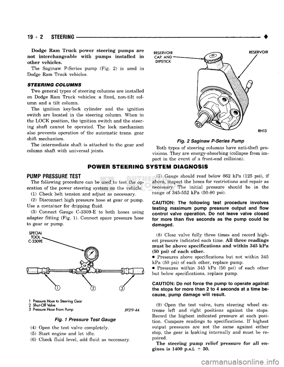
dripping fluid. (3) Connect Gauge C-3309-E
to
both hoses using
adapter fitting
(Fig. 1).
Connect spare pressure hose
to gear
or
pump.
SPECIAL
1
Pressure
Hose
to
Steering
Gear
2
Shut-Off
Valve
3
Pressure
Hose
From Pump
J9219-44
Fig.
1
Pressure
Test
Gauge
(4) Open
the
test valve completely.
(5) Start engine
and let
idle.
(6) Check fluid level,
add
fluid
as
necessary.
Fig.
2
Saginaw
P-Series
Pump
Both types
of
steering columns have anti-theft pro
visions. They
are
energy-absorbing (collapse from
im
pact
in the
event
of a
front-end collision).
SYSTEM DIAGNOSIS
(7) Gauge should read below
862 kPa (125 psi), if
above, inspect
the
hoses
for
restrictions
and
repair
as
necessary.
The
initial pressure should
be in the
range
of
345-552
kPa
(50-80
psi).
CAUTION:
The
following test procedure involves
testing
maximum
pump pressure output
and
flow control valve operation.
Do not
leave valve closed
for more than five
seconds
as the
pump could
be
damaged.
(8) Close valve fully three times
and
record high
est pressure indicated each time.
All
three readings
must
be
above specifications
and
within
345 kPa
(50
psi) of
each other.
9
Pressures above specifications
but not
within
345
kPa
(50 psi) of
each other, replace pump. • Pressures within
345 kPa (50 psi) of
each other
but below specifications, replace pump.
CAUTION:
Do not
force
the
pump
to
operate against
the
stops
for
more than
2 to 4
seconds
at a
time
be
cause,
pump damage
will
result.
(9) Open
the
test valve, turn steering wheel
ex
treme left
and
right positions against
the
stops.
Record
the
highest indicated pressure
at
each posi
tion. Compare readings
to
specifications.
If
highest output pressures
are not the
same against either
stop,
the
gear
is
leaking internally
and
must
be re
paired.
The steering pump relief pressure
for all en
gines
is 1400
p.s.i.
± 50.
Page 998 of 1502
•
STEERING
19 • 37 (4) From the end of travel, rotate the rotor 2 1/2
full turns in the COUNTER CLOCKWISE direction.
The horn wire should end up at the top and the squib
wire at the bottom (Fig. 4).
(5) Install the steering wheel, refer to Steering
Wheel Installation.
COLUMN—
REMOVAL/INSTALLATION
CAUTION:
Bumping,
jolting
and
hammering
on the
steering
column
shaft
and
gear
shift
tube
must
be
avoided
during
all
service
procedures.
REMOVAL (1) Make sure the front wheels are in the straight
ahead position.
(2) Disconnect the negative (ground) cable from
the battery.
(3) Remove steering wheel from column, refer to
Steering Wheel-Removal.
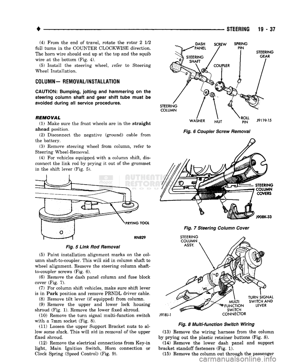
(4) For vehicles equipped with a column shift, dis
connect the link rod by prying it out of the grommet in the shift lever (Fig. 5).
DASH
"PANEL SCREW
SPRING
PIN
PRYING
TOOL
RN829
Fig.
5
Link
Rod
Removal
(5) Paint installation alignment marks on the col
umn shaft-to-coupler. This will aid in column shaft to
wheel alignment. Remove the steering column shaft-
to-coupler screws (Fig. 6).
(6) Remove the dash panel column and fuse block
cover (Fig. 7).
(7) For column shift vehicles, make sure shift lever
is in Park position and remove PRNDL driver cable.
(8) Remove tilt lever (if equipped) from column.
(9) Remove the upper and lower lock housing
shroud (Fig. 1). Remove the lower fixed shroud.
(10) Remove the turn signal multi-function switch
with a 7mm socket (Fig. 8). (11) Loosen the upper Support Bracket nuts to al
low some slack. This will aid in removal of the upper
fixed shroud.
(12) Remove the electrical connections from Key-in
light, Main Ignition Switch, Horn connection or
Clock
Spring (Speed
Control)
(Fig. 9).
STEERING
GEAR
STEERING COLUMN
WASHER NUT
RJ?N"
J9119-15
Fig.
6
Coupler
Screw
Removal
STEERING COLUMN COVERS
J908K-33
Fig.
7 Steering
Column
Cover
STEERING COLUMN
ASSY.
J918J-1
MULTI
^FUNCTION
SWITCH
CONNECTOR
TURN
SIGNAL
SWITCH
AND
LEVER
Fig.
8 Multi-function
Switch
Wiring (13) Remove the wiring harness from the column
by prying out the plastic retainer buttons (Fig. 8).
(14) Remove the lower dash panel and support
bracket standoff fasteners (Fig. 1). (15) Remove the column out through the passenger
Page 1084 of 1502
•
AUTOMATIC TRANSiISSIO|-32RH/8iRH/37RH/42RH/4iRH
21 - 83 plate. The overdrive clutch also disengages the direct
clutch during 3-4 upshifts. As fluid pressure extends
the overdrive piston, the piston contacts the direct clutch hub pressing it rearward. This action com
presses the direct clutch spring relieving spring load on the clutch pack. The clutch is disengaged once
spring load is relieved.
The 3-4 accumulator cushions overdrive clutch en
gagement to smooth the transition into fourth gear.
The accumulator is charged at the same time as ap
ply pressure acts against the overdrive piston.
Converter clutch engagement in overdrive fourth
gear is controlled by sensor inputs to the powertrain
control module. In third gear above 25 mph, sensor inputs to the control module that determine clutch
engagement and shift timing are:
• coolant temperature (verifies minimum of 60° F)
• engine speed • vehicle speed
• throttle position
• manifold vacuum (MAP sensor)
Gearshift
Mechanism
The gear shift mechanism provides the same shift
positions used with 3-speed Chrysler transmissions
(P-R-N-D-2-1).
The shift into overdrive fourth gear range occurs
only after the transmission has completed the shift into D third gear range. No further movement of the
shift mechanism is required to complete the 3-4 shift.
The fourth gear upshift occurs automatically when
the overdrive control switch is in the ON position. Shift timing is determined by sensor inputs to the
engine controller.
Overdrive Control
Switch
The overdrive control switch is located in the in
strument panel. In the On position, automatic shifts
into fourth gear overdrive will occur. In the Off posi
tion, the switch overrides the engine controller pre
venting a shift to overdrive fourth gear range.
The switch has an indicator light that illuminates
when overdrive is turned off. The switch also resets
when the ignition key is turned to the OFF position so that the automatic overdrive feature is restored.
The use of fault codes is employed to help diagnose
the electronic components that operate the overdrive
unit and converter clutch.
HYDRAULIC
CONTROLS
The 42REJ/46RH hydraulic control system provides
fully automatic operation. The system performs five
basic functions which are: pressure supply, pressure regulation, flow control, clutch/band application, and
lubrication. 42RH/46RH system operation is similar to that de
scribed in the 32RH/36RH/37RH General Informa tion section. The main difference being fourth gear
operation which is covered here.
Pressure
Regulation
The pressure regulator valve maintains line pres
sure.
The amount of pressure developed is controlled
by throttle pressure which is dependent on the de gree of throttle opening. The regulator valve is lo
cated in the valve body.
The throttle valve determines line pressure and
shift speed. Governor pressure increases in propor
tion to vehicle speed. The throttle valve controls up shift and downshift speeds by regulating pressure
according to throttle position.
Flow
Control And Lubrication The manual valve is operated by the gearshift link
age and provides the operating range selected by the
driver.
The 1-2 shift valve provides 1-2 or 2-1 shifts and
the 2-3 shift valve provides 2-3 or 3-2 shifts.
The kickdown valve provides forced 3-2 or 3-1
downshifts depending on vehicle speed. Downshifts
occur when the throttle is opened beyond downshift
detent position which is just before wide open throt
tle.
The 2-3 valve throttle pressure plug provides 3-2
downshifts at varying throttle openings depending on
vehicle speed.
The 1-2 shift control valve transmits 1-2 shift pres
sure to the accumulator piston. This controls kick-
down band capacity on 1-2 upshifts and 3-2 downshifts.
The 3-4 shift valve, shuttle valve, timing valve and
accumulator are only actuated when the overdrive
solenoid is energized.
The solenoid contains a check ball that controls a
vent port to the 3-4 valve. The check ball either di
verts line pressure away from or directly to, the 3-4 shift valve. Energizing the solenoid causes the check
ball to close the vent port allowing line pressure to act upon the 3-4 upshift valve.
The limit valve determines maximum speed at
which a 3-2 part throttle kickdown can be made. Some transmissions do not have the limit valve and
maximum speed for a 3-2 kickdown is at the detent
position.
The 2-3 shuttle valve has two functions. First is
fast front band release and smooth engagement dur ing lift-foot 2-3 upshifts. The second is to regulate
front clutch and band application during 3-2 down
shifts.
The 3-4 shuttle valve uses a combination of throt
tle and governor pressure to control the rate of over
drive piston apply and release. This is done to
maintain shift quality at varying throttle openings.
Page 1132 of 1502
•
IN-VEHICLE
SERVICE-32RH/36RH/37RH/42RH/46RH
21 - 131
Fig.
1
Column
Gearshift
Linkage
LINKAGE
ADJUSTMENT
PROCEDURE
Do
not
attempt
linkage
adjustment
if any
compo
nents
are
worn
or
damaged.
If
either linkage
rod
must
be
disconnected,
the plastic
grommet secur
ing
the rod in the
torque shaft lever must
be re
placed. Disconnect
the rod
with
a pry
tool.
Pry
only where
the
grommet
and rod
attach
and not on
the
rod
itself.
Then
cut
away
the old
grommet.
Use
pliers
to
snap
the new
grommet into
the
lever
and
to snap
the rod
into
the
grommet.
(1) Shift transmission into Park.
(2) Raise vehicle.
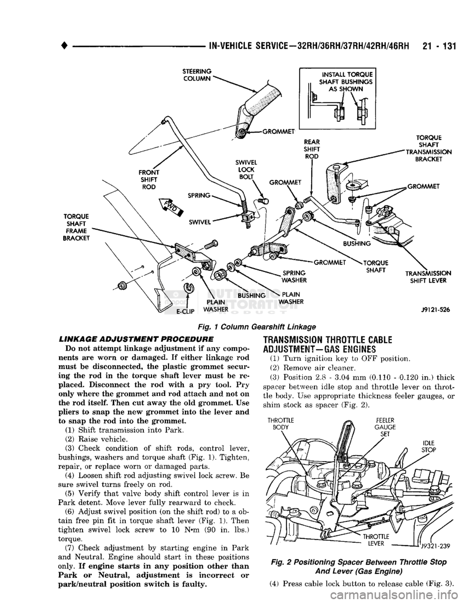
(3) Check condition
of
shift rods, control lever,
bushings, washers
and
torque shaft
(Fig.
1). Tighten,
repair,
or
replace worn
or
damaged parts. (4) Loosen shift rod adjusting swivel lock screw.
Be
sure swivel turns freely
on rod.
(5) Verify that valve body shift control lever
is in
Park detent. Move lever fully rearward
to
check. (6) Adjust swivel position
(on the
shift rod)
to a ob
tain free
pin fit in
torque shaft lever
(Fig. 1).
Then
tighten swivel lock screw
to 10 N»m (90 in. lbs.)
torque.
(7) Check adjustment
by
starting engine
in
Park
and Neutral. Engine should start
in
these positions
only. If
engine starts
in any
position other than
Park
or
Neutral, adjustment
is
incorrect
or
park/neutral position switch
is
faulty.
TRANSMISSION
THROTTLE
CABLE
ADJUSTMENT-GAS
ENGINES
(1)
Turn ignition
key to OFF
position.
(2)
Remove
air
cleaner.
(3)
Position 2.8
-
3.04
mm
(0.110
-
0.120
in.)
thick
spacer between idle stop
and
throttle lever
on
throt
tle body.
Use
appropriate thickness feeler gauges,
or
shim stock
as
spacer
(Fig. 2).
Fig.
2
Positioning
Spacer
Between
Throttle
Stop
And
Lever
(Gas
Engine)
(4) Press cable lock button
to
release cable
(Fig. 3).
Page 1479 of 1502
25
- 2
EMISSION
CONTROL
SYSTEMS
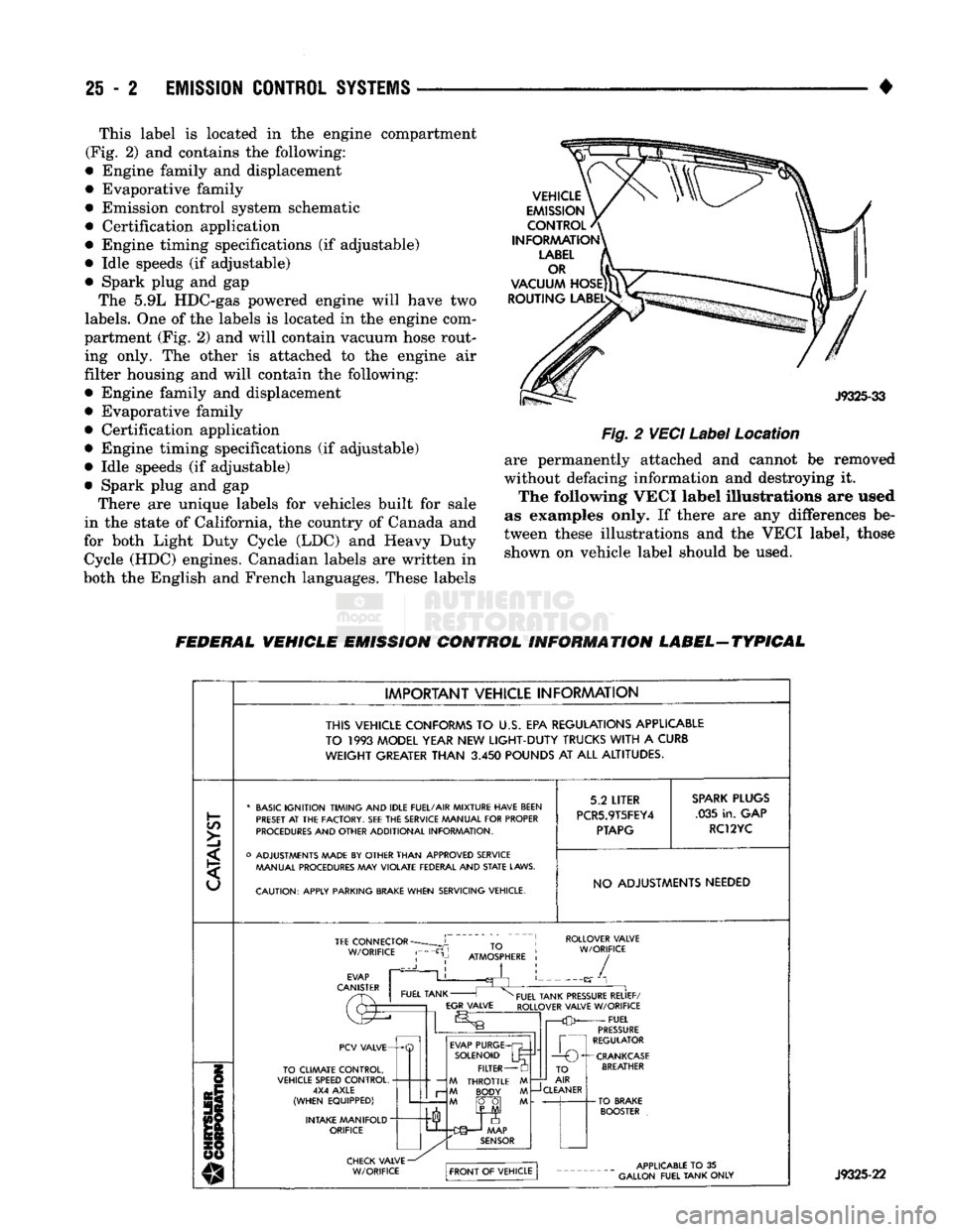
• This label is located in the engine compartment
(Fig. 2) and contains the following:
• Engine family and displacement
• Evaporative family
• Emission control system schematic
• Certification application
• Engine timing specifications (if adjustable)
• Idle speeds (if adjustable)
• Spark plug and gap The 5.9L HDC-gas powered engine will have two
labels.
One of the labels is located in the engine com
partment (Fig. 2) and will contain vacuum hose rout ing only. The other is attached to the engine air
filter housing and will contain the following:
• Engine family and displacement
• Evaporative family
• Certification application
• Engine timing specifications (if adjustable)
• Idle speeds (if adjustable)
• Spark plug and gap There are unique labels for vehicles built for sale
in the state of California, the country of Canada and
for both Light Duty Cycle (LDC) and Heavy Duty Cycle (HDC) engines. Canadian labels are written in
both the English and French languages. These labels
Fig.
2
VECI
Label
Location
are permanently attached and cannot be removed
without defacing information and destroying it. The following VECI label illustrations are used
as examples only. If there are any differences be
tween these illustrations and the VECI label, those shown on vehicle label should be used.
FEDERAL VEHICLE EMISSION CONTROL INFORMATION LABEL-TYPICAL
IMPORTANT VEHICLE INFORMATION
THIS VEHICLE CONFORMS
TO U.S. EPA
REGULATIONS APPLICABLE
TO
1993
MODEL YEAR
NEW
LIGHT-DUTY
TRUCKS
WITH
A
CURB
WEIGHT
GREATER
THAN
3.450
POUNDS
AT ALL
ALTITUDES.
C/5
>]
* BASIC IGNITION TIMING AND IDLE FUEL/AIR MIXTURE HAVE BEEN
PRESET
AT THE
FACTORY.
SEE THE
SERVICE MANUAL FOR PROPER
PROCEDURES AND OTHER ADDITIONAL INFORMATION.
o ADJUSTMENTS MADE
BY
OTHER THAN APPROVED SERVICE MANUAL PROCEDURES
MAY
VIOLATE FEDERAL AND
STATE
LAWS.
CAUTION: APPLY PARKING
BRAKE
WHEN SERVICING VEHICLE. 5.2
LITER
PCR5.9T5FEY4
PTAPG
SPARK
PLUGS
.035 in. GAP
RC12YC
NO ADJUSTMENTS NEEDED TEE
CONNECTOR
W/ORIFICE ROLLOVER VALVE
W/ORIFICE
PCV VALVE-
TO CLIMATE CONTROL,
VEHICLE SPEED CONTROL, 4X4 AXLE
(WHEN EQUIPPED)
INTAKE MANIFOLD
"
ORIFICE EVAP PURGE
SOLENOID FILTER
M THROTTLE M M BODY M
M fO~0| M TO
AIR
—J
CLEANER
-CRANKCASE
BREATHER J9325-22