1993 DODGE TRUCK ignition
[x] Cancel search: ignitionPage 249 of 1502
i - 62
BRAKES
•
Isolation/Dump
Valve Cycle Times
Activation (opening/closing) of the isolation and
dump valves is continuous during antilock operation.
The valves cycle rapidly in response to speed sensor inputs and control module signal commands. Cycle
times are measured in milliseconds.
As the demand for antilock mode brake operation
is decreased, the module deactivates the hydraulic
valve components to restore normal brake operation.
ANTILOCK
SERVICE
DIAGNOSIS
GENERAL INFORMATION An antilock system malfunction will be indicated
by illumination of the amber antilock warning lamp.
The red brake warning lamp may also illuminate.
If a problem occurs, system diagnosis should begin
with a fluid level check followed by a visual exami
nation of the system electrical and hydraulic connec
tions.
If obvious defects (low fluid, leaks, loose connections, etc.) are not evident, road test the vehi
cle.
A road test should help determine if a malfunc
tion is actually related to an antilock component.
During the road test, note if other conditions are
evident such as a low pedal, pull, grab, or similar condition. Remember that brake malfunctions such as low fluid, system leaks, parking brakes partially
applied, will also affect the antilock system. The idea
is to determine if a malfunction is actually related to
an anti-lock component.
If a road test does reveal a problem, repeat the
road test with the owner driving. Make sure the owner is not riding the brake pedal, or has forgotten
to release the parking brakes. Either situation will
generate a fault and cause the antilock light to illu
minate.
SYSTEM FAULT
CODES
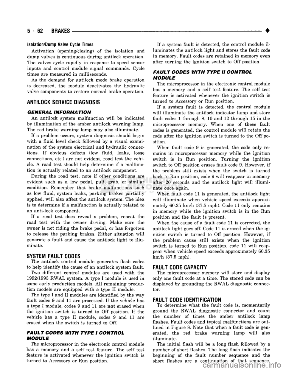
The antilock control module generates flash codes
to help identify the cause of an antilock system fault. Two different control modules are used with the
1992/1993 RWAL system. A type I module is used in
some early production models. All remaining produc
tion models are equipped with a type II module. The type I and II modules are identified by the way
fault codes 9 and 11 are processed. If the vehicle has a type I module, codes 9 and 11 are not erased when
the ignition switch is turned to Off position. If the vehicle has a type II module, codes 9 and 11 are
erased when the switch is turned to Off.
FAULT CODES WITH TYPE I CONTROL
MODULE
The microprocessor in the electronic control module
has a memory and a self test feature. The self test
feature is activated whenever the ignition switch is
turned to Accessory or Run position. If a system fault is detected, the control module il
luminates the antilock light and stores the fault code
in memory. Fault codes are retained in memory even after turning the ignition switch to Off position.
FAULT CODES WITH TYPE II CONTROL
MODULE The microprocessor in the electronic control module
has a memory and a self test feature. The self test
feature is activated whenever the ignition switch is
turned to Accessory or Run position.
If a system fault is detected, the control module
will illuminate the antilock indicator lamp and store
fault codes 1 through 8, 10 and 12 through 15 in the
microprocessor memory. When one of these fault
codes is generated, the control module will retain the code after the ignition switch is turned to the Off po
sition.
When fault code 9 is generated, the code only re
mains in microprocessor memory while the ignition switch is in Run position. Turning the ignition
switch to Off position erases fault code 9. However, if
the problem still exists when the switch is turned
back to Run position, code 9 will reappear in memory after 20 seconds and the antilock light will illumi
nate once again.
When fault code 11 is generated, the antilock light
will illuminate when vehicle speed exceeds approxi mately 60.35 km/h (37.5 mph). Code 11 only remains in memory while the ignition switch is in the Run
position and the fault is present.
When the cause of a fault code 11 is corrected, the
antilock light goes off. Code 11 is erased when the ig
nition switch is turned to Off position. However, if
the problem cause still exists when the ignition switch is turned to Run position, code 11 will reap
pear when vehicle speed exceeds approximately 60.35 km/h (37.5 mph).
FAULT
CODE
CAPACITY
The microprocessor memory will store and display
only one fault code at a time. The stored code can be
displayed by grounding the RWAL diagnostic connec
tor.
FAULT
CODE
IDENTIFICATION
To determine what the fault code is, momentarily
ground the RWAL diagnostic connector and count
the number of times the amber antilock lamp flashes. Fault codes and typical malfunctions are outlined in Figure 8. Note that when a fault code is gen
erated, the red brake warning lamp will also
illuminate. The initial flash will be a long flash followed by a
number of short flashes. The long flash indicates the
beginning of the fault number sequence and the short flashes are a continuation of that sequence.
Page 275 of 1502
DIAGNOSIS
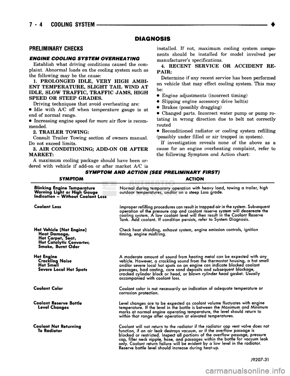
PRELIMINARY
CHECKS
ENGINE COOLING SYSTEM OVERHEATING Establish what driving conditions caused the com
plaint. Abnormal loads on the cooling system such as
the following may be the cause:
1.
PROLONGED IDLE, VERY HIGH AMBI
ENT TEMPERATURE, SLIGHT TAIL WIND AT
IDLE, SLOW TRAFFIC, TRAFFIC JAMS, HIGH SPEED OR STEEP GRADES.
Driving techniques that avoid overheating are:
• Idle with A/C off when temperature gauge is at
end of normal range. * Increasing engine speed for more air flow is recom
mended.
2.
TRAILER TOWING: Consult Trailer Towing section of owners manual.
Do not exceed limits.
3.
AIR CONDITIONING; ADD-ON OR AFTER
MARKET: A maximum cooling package should have been or
dered with vehicle if add-on or after market A/C is
SYMPTOM AND ACTION
SYMPTOM
installed. If not, maximum cooling system compo
nents should be installed for model involved per
manufacturer's specifications.
4.
RECENT SERVICE OR ACCIDENT RE
PAIR:
Determine if any recent service has been performed
on vehicle that may effect cooling system. This may
be:
• Engine adjustments (incorrect timing)
• Slipping engine accessory drive belt(s) • Brakes (possibly dragging)
• Changed parts. Incorrect water pump or pump ro
tating in wrong direction due to belt not correctly
routed
• Reconditioned radiator or cooling system refilling (possibly under filled or air trapped in system).
If investigation reveals none of the above as a
cause for an engine overheating complaint, refer to
the following Symptom and Action chart:
PRELIMINARY FIRST) ACTION
Blinking Engine Temperature
Warning Light or High Gauge indication - Without Coolant Loss
Normal during temporary operation
with
heavy load, towing
a
trailer,
high
outdoor temperatures, and/or on
a
steep
Loss
grade.
Coolant Loss
Hot Vehicle (Not Engine) Heat Damage,
Hot Carpet, Seat,
Hot
Catalytic
Converter,
Smoke, Burnt Odor
Hot Engine Crackling Noise Hot Smell
Severe Local Hot Spots
Coolant Color
Coolant Reserve Bottle Level Changes
Coolant Not Returning To Radiator
Improper refilling procedures
can
result
in
trapped air
in
the
system.
Subsequent
operation
of the
pressure cap and coolant reserve system
will
deaereate
the
cooling
system.
A low
coolant
level
will
then result
in the
Coolant Reserve
Tank. Add coolant.
If
condition persists,
refer
to
System
Diagnosis.
Check
heat shielding, exhaust
system,
engine emission controls, ignition
timing, engine misfiring.
A
moderate amount
of
sound from heating
metal
can
be
expected
with
any
vehicle. However,
a
crackling sound from
trie
thermostat
housing,
a hot
smell and/or severe local
hot
spots on
an
engine can indicate blocked coolant
passages,
bad castina, core sand deposits and subsequent blockage,
cracked cylinder block
or
head,
or
blown cylinder head gasket. Usually
accompanied
with
coolant
loss.
Coolant
color is
not
necessarily
an
indication
of
adequate
temperature
or
corrosion
protection.
Level changes
are to be
expected as coolant volume fluctuates
with
engine
temperature.
If the
level
in the
bottle
is
between
the
Maximum and Minimum
marks
at
normal engine operating temperature,
the
level
should
return
to
within
that
range
after
operation
at
elevated temperatures.
Coolant
will
not
return
to the
radiator
if the
radiator cap vent valve does
not
function,
if
an
air
leak destroys vacuum,
or if the
overflow
passage
is
blocked
or
restricted. Inspect
all
portions
of the
overflow
passage,
pressure
cap,
filler
neck nipple, hose, and
passages
within
the
bottle
for
vacuum leak
only. Coolant
return
failure
will
be
evident
by a low
level
in the
radiator.
Reserve
bottle
level
should increase during heat-up.
J9207-31
Page 279 of 1502
7 - 8
COOLING
SYSTEM
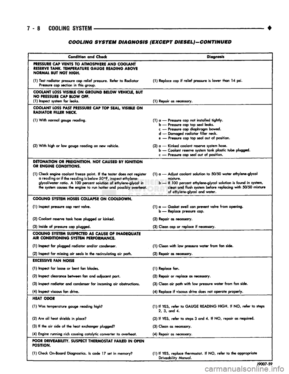
COOLING SYSTEM DIAGNOSIS (EXCEPT DIESEL)—CONTINUED
Condition and Check
Diagnosis
PRESSURE
CAP
VENTS
TO
ATMOSPHERE
AND COOLANT
RESERVE
TANK.
TEMPERATURE
GAUGE
READING
ABOVE
NORMAL
BUT NOT HIGH.
(1) Test radiator pressure cap
relief
pressure. Refer to Radiator Pressure cap section in this group. (1) Replace cap if
relief
pressure is lower than 14 psi.
COOLANT
LOSS
VISIBLE
ON
GROUND
BELOW
VEHICLE,
BUT
NO
PRESSURE
CAP
BLOW
OFF.
(1) Inspect
system
for leaks. (1) Repair as necessary.
COOLANT
LOSS
PAST
PRESSURE
CAP
TOP
SEAL,
VISIBLE
ON
RADIATOR
FILLER
NECK.
(1) With normal gauge reading. (1) a — Pressure cap not installed tightly.
b — Pressure cap top seal leaks.
c
— Pressure cap diaphragm bowed.
d — Damaged radiator
filler
neck.
e — Pressure cap top seal out of position.
(2) With high or low gauge reading on new vehicle. (2) a — Kinked coolant reserve
system
hose.
b — Coolant reserve
system
tank
plastic
tube
plugged,
c
— Pressure cap seal out of position.
DETONATION
OR
PREIGNITION.
NOT
CAUSED
BY IGNITION
OR
ENGINE
CONDITIONS.
(1) Check engine coolant
freeze
point. If the
tester
does
not register a reading or if
the
reading
is
below
50°F,
inspect
ethylene-
glycol/water
ratio.
A 100
percent
solution of ethylene-glycol in
the
system
causes
the engine to run
hotter
and
possibly
overheat. (1) a — Adjust coolant solution to
50/50
water
ethylene-glycol
mixture.
b — If 100
percent
ethylene-glycol solution
is
found in system, clean and flush
system
before
replacing
with
50/50
mixture
of ethylene-glycol and
water.
COOLING
SYSTEM
HOSES
COLLAPSE
ON
COOLDOWN.
(1) Inspect pressure cap
vent
valve. (1) a — Gasket swell can
prevent
valve from opening,
b — Replace pressure cap.
(2) Coolant reserve
tank
hose plugged or kinked. (2) Repair as necessary.
(3) Inside of pressure cap plugged. (3) Clean cap or replace if necessary.
COOLING
SYSTEM
SUSPECTED
AS
CAUSE
OF
INADEQUATE
AIR
CONDITIONING
SYSTEM
PERFORMANCE.
(1) Inspect for plugged radiator and/or condenser. (1) Clean
with
low pressure
water
from fan side.
(2) Inspect for
missing
air
seals
in the recirculating air path. (2) Repair as necessary.
EXCESSIVE
FAN
NOISE
(1) Inspect for loose or
bent
fan blades. (1) Replace fan.
(2) Inspect clearance
between
fan and adjacent
part.
(2) Repair or replace as necessary.
(3) Inspect radiator and condenser for incoming air obstructions. (3) Clean air path
with
low pressure
water
from fan side.
(4) Inspect
viscous
fan drive. (4) Replace if
viscous
drive
does not
operate
properly.
HEAT
ODOR
(1) Was
temperature
gauge reading
high?
(1) If
YES,
refer
to
GAUGE
READING
HIGH. If NO,
refer
to steps
2, 3, and 4.
(2) Are all
heat
shields in place? (2) If
YES,
refer
to
steps
3 and 4. If NO,
repair
as required.
(3) If the air side of the
heat
exchanger
plugged?
(3) Clean as necessary.
(4) Engine running rich
causing
catalytic converter to overheat. (4) Repair as necessary.
POOR
DRIVEABIUTY.
SUSPECT
THERMOSTAT
FAILED
IN
OPEN
POSITION.
(1) Check On-Board
Diagnostics.
Is code 17 set in memory? (1) If
YES,
replace thermostat. If NO,
refer
to the appropriate
Driveability Manual.
J9007-59
Page 284 of 1502
•
COOLING SYSTEM 7-13
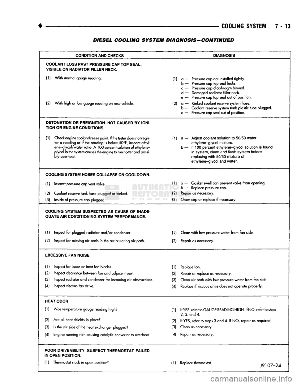
DIESEL COOLING SYSTEM DIAGNOSIS-CONTINUED
CONDITION
AND
CHECKS
DIAGNOSIS
COOLANT
LOSS
PAST
PRESSURE
CAP
TOP
SEAL,
VISIBLE
ON
RADIATOR
FILLER
NECK.
(1)
With
normal gauge reading. (1) a — Pressure cap not installed
tightly.
b — Pressure cap top seal leaks.
c
— Pressure cap diaphragm bowed.
d
— Damaged
radiator
filler
neck.
e — Pressure cap top seal out of position.
(2)
With
high or low gauge reading on new vehicle. (2) a — Kinked coolant reserve system hose.
(2)
With
high or low gauge reading on new vehicle.
b — Coolant reserve system
tank
plastic
tube
plugged.
c
— Pressure cap seal out of position.
DETONATION
OR
PREIGNITION.
NOT
CAUSED
BY
IGNI
TION OR
ENGINE
CONDITIONS.
(1)
Check engine coolant
freeze
point.
If the
tester
does
not
regis
(1) a — Adjust coolant solution to
50/50
water
ter a reading or if the reading is below 50°F, inspect
ethyl
ethylene-glycol
mixture.
ene-glycol/
water
ratio.
A 100
percent
solution of
ethylene-
b — If 100
percent
ethylene-glycol
solution is found
glycol
in
the
system
causes
the engine
to
run
hotter
and
possi
in system,
clean
and flush system
before
bly overheat.
replacing
with
50/50
mixture
of
ethylene-glycol
and
water.
COOLING
SYSTEM
HOSES
COLLAPSE
ON
COOLDOWN.
(1) Inspect pressure cap
vent
valve. (1) a — Gasket swell can
prevent
valve
from
opening.
b — Replace pressure cap.
(2) Coolant reserve
tank
hose plugged or kinked. (2) Repair as necessary.
(3) Inside of pressure cap plugged. (3) Clean cap or
replace
if necessary.
COOLING
SYSTEM
SUSPECTED
AS
CAUSE
OF
INADE
QUATE
AIR CONDITIONING
SYSTEM
PERFORMANCE.
(1) Inspect for plugged
radiator
and/or condenser. (D Clean
with
low pressure
water
from
fan side.
(2) Inspect for
missing
air
seals
in the
recirculating
air path. (2) Repair
as
necessary.
EXCESSIVE
FAN
NOISE
(1)
Inspect for loose or
bent
fan blades. (1) Replace fan.
(2) Inspect clearance
between
fan and
adjacent
part.
(2) Repair or
replace
as necessary.
(3) Inspect
radiator
and condenser for incoming air obstructions. (3) Clean air path
with
low pressure
water
from
fan side.
(4) Inspect
viscous
fan drive. (4) Replace if
viscous
drive
does not
operate
properly.
HEAT
ODOR
(1)
Was
temperature
gauge reading high? (1) If
YES,
refer
to
GAUGE
READING
HIGH.
If
NO,
refer
to
steps
2, 3, and 4.
(2) Are all
heat
shields in place? (2) If
YES,
refer
to steps 3 and 4. If NO,
repair
as
required.
(3)
Is
the air side of the
heat
exchanger plugged? (3) Clean as necessary.
(4) Engine running rich causing
catalytic
converter
to overheat. (4) Repair
as
necessary.
POOR
DRIVEABILITY.
SUSPECT
THERMOSTAT FAILED
IN OPEN POSITION.
(1)
Thermostat stuck in open position? 01 Replace thermostat. ._ _0 .
Jy
107-24
Page 291 of 1502
7 - 20
COOLING
SYSTEM
•
HOSE
CLAMP
HOSE
J9207-36
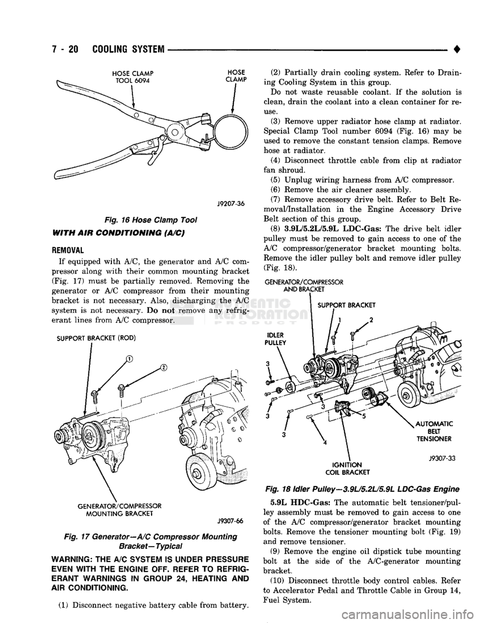
Fig.
16
Hose
Clamp
Tool
WITH AIR
CONDITIONING
(A/C)
REMOVAL
If equipped with A/C, the generator and A/C com
pressor along with their common mounting bracket (Fig. 17) must be partially removed. Removing the
generator or A/C compressor from their mounting
bracket is not necessary. Also, discharging the A/C system is not necessary. Do not remove any refrig
erant lines from A/C compressor.
SUPPORT BRACKET (ROD)
GENERATOR/COMPRESSOR
MOUNTING
BRACKET
J9307-66
Fig.
17 Generator—A/C
Compressor
Mounting
Bracket—
Typical
WARNING;
THE A/C
SYSTEM
IS
UNDER
PRESSURE
EVEN
WITH
THE
ENGINE OFF. REFER
TO
REFRIG
ERANT
WARNINGS
IN
GROUP
24,
HEATING
AND
AIR
CONDITIONING.
(1) Disconnect negative battery cable from battery. (2) Partially drain cooling system. Refer to Drain
ing Cooling System in this group.
Do not waste reusable coolant. If the solution is
clean, drain the coolant into a clean container for re
use.
(3) Remove upper radiator hose clamp at radiator.
Special Clamp Tool number 6094 (Fig. 16) may be
used to remove the constant tension clamps. Remove
hose at radiator.
(4) Disconnect throttle cable from clip at radiator
fan shroud. (5) Unplug wiring harness from A/C compressor.
(6) Remove the air cleaner assembly.
(7) Remove accessory drive belt. Refer to Belt Re
moval/Installation in the Engine Accessory Drive
Belt section of this group.
(8) 3.9L/5.2L/5.9L LDC-Gas: The drive belt idler
pulley must be removed to gain access to one of the
A/C compressor/generator bracket mounting bolts. Remove the idler pulley bolt and remove idler pulley (Fig. 18).
GENERATOR/COMPRESSOR
AND
BRACKET
SUPPORT BRACKET
IGNITION
COIL
BRACKET
Fig.
18 Idler Pulley-3.9U5.2U5.9L
LDC-Gas
Engine
5.9L HDC-Gas: The automatic belt tensioner/pul-
ley assembly must be removed to gain access to one
of the A/C compressor/generator bracket mounting
bolts.
Remove the tensioner mounting bolt (Fig. 19) and remove tensioner.
(9) Remove the engine oil dipstick tube mounting
bolt at the side of the A/C-generator mounting
bracket.
(10) Disconnect throttle body control cables. Refer
to Accelerator Pedal and Throttle Cable in Group 14,
Fuel System.
Page 299 of 1502
7 - 28
COOLING SYSTEM
DO NOT WASTE reusable coolant. If the solution
is clean, drain the coolant into a clean container for
reuse.
(1) Start the engine and place the heater control
temperature selector in the Full On position. Engine vacuum is needed to actuate the heater controls.
(2) Turn the ignition off. (3) Do not remove radiator cap when draining cool
ant from reserve/overflow tank. Open radiator drain
plug and when tank is empty, remove radiator cap. If
the coolant reserve/overflow tank does not drain, re fer to the Testing Cooling System for Leaks section
in this group. The coolant need not be removed from
tank unless the system is being refilled with fresh mixture.
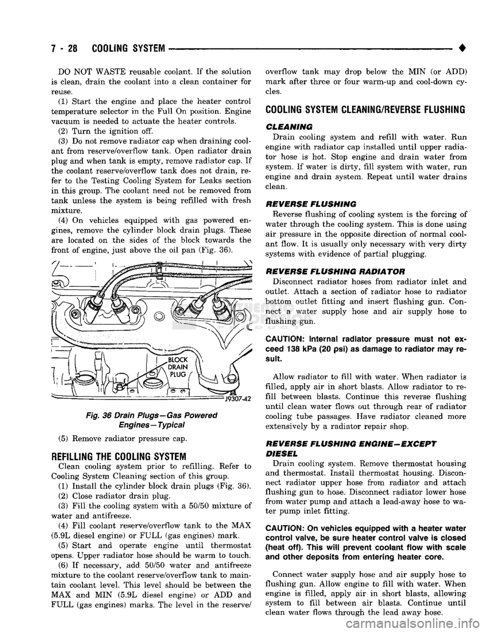
(4) On vehicles equipped with gas powered en
gines,
remove the cylinder block drain plugs. These are located on the sides of the block towards the
front of engine, just above the oil pan (Fig. 36).
Fig.
36 Drain Plugs—Gas Powered
Engines—Typical
(5) Remove radiator pressure cap.
REFILLING
THE
COOLING SYSTEM
Clean cooling system prior to refilling. Refer to
Cooling System Cleaning section of this group. (1) Install the cylinder block drain plugs (Fig. 36).
(2)
Close radiator drain plug.
(3) Fill the cooling system with a 50/50 mixture of
water and antifreeze. (4) Fill coolant reserve/overflow tank to the MAX
(5.9L diesel engine) or FULL (gas engines) mark. (5) Start and operate engine until thermostat
opens. Upper radiator hose should be warm to touch. (6) If necessary, add 50/50 water and antifreeze
mixture to the coolant reserve/overflow tank to main
tain coolant level. This level should be between the MAX and MIN (5.9L diesel engine) or ADD and FULL (gas engines) marks. The level in the reserve/ overflow tank may drop below the MIN (or ADD)
mark after three or four warm-up and cool-down cy
cles.
COOLING SYSTEM CLEANING/REVERSE FLUSHING
CLEMMING Drain cooling system and refill with water. Run
engine with radiator cap installed until upper radia
tor hose is hot. Stop engine and drain water from system. If water is dirty, fill system with water, run
engine and drain system. Repeat until water drains
clean.
REVERSE
FLUSHING
Reverse flushing of cooling system is the forcing of
water through the cooling system. This is done using air pressure in the opposite direction of normal cool
ant flow. It is usually only necessary with very dirty
systems with evidence of partial plugging.
REVERSE
FLUSHING
RADIATOR Disconnect radiator hoses from radiator inlet and
outlet. Attach a section of radiator hose to radiator
bottom outlet fitting and insert flushing gun. Con
nect a water supply hose and air supply hose to flushing gun.
CAUTION:
Internal
radiator
pressure must
not'ex
ceed 138 kPa (20 psi) as damage to
radiator
may re
sult
Allow radiator to fill with water. When radiator is
filled, apply air in short blasts. Allow radiator to re
fill between blasts. Continue this reverse flushing
until clean water flows out through rear of radiator cooling tube passages. Have radiator cleaned more extensively by a radiator repair shop.
REVERSE
FLUSHING
ENGINE-EXCEPT DIESEL Drain cooling system. Remove thermostat housing
and thermostat. Install thermostat housing. Discon
nect radiator upper hose from radiator and attach
flushing gun to hose. Disconnect radiator lower hose
from water pump and attach a lead-away hose to wa
ter pump inlet fitting.
CAUTION;
On vehicles equipped
with
a
heater
water
control
valve, be sure
heater
control
valve is closed
(heat
off). This
will
prevent
coolant
flow
with
scale
and
other
deposits
from
entering
heater
core.
Connect water supply hose and air supply hose to
flushing gun. Allow engine to fill with water. When engine is filled, apply air in short blasts, allowing system to fill between air blasts. Continue until
clean water flows through the lead away hose.
Page 317 of 1502
7
- 4S
COOLING
SYSTEM
•
PULLEY BOLT IDLER
iUlLTPULLEY-
TENSIONER
MOUNTING
BOLT TENSIONER
ASSEMBLY
TENSIONER \
rULLC,\
, / ^ J9307-64 ,
Fig.
11 Beit Tensioner—5.9L
HDC-Gas
Engine
MOUNT.
BOLT
3/8
SQUARE HOLE
ACCESSORY
DRIVE
BELT AUTOMATIC
BELT
TENSIONER
J9307-59
Fig.
12 Belt Tensioner—5.9L
Diesel
Engine—Typical
3MLm.2Lm.9L
LDG°GA8
ENGINES
REMOVAL
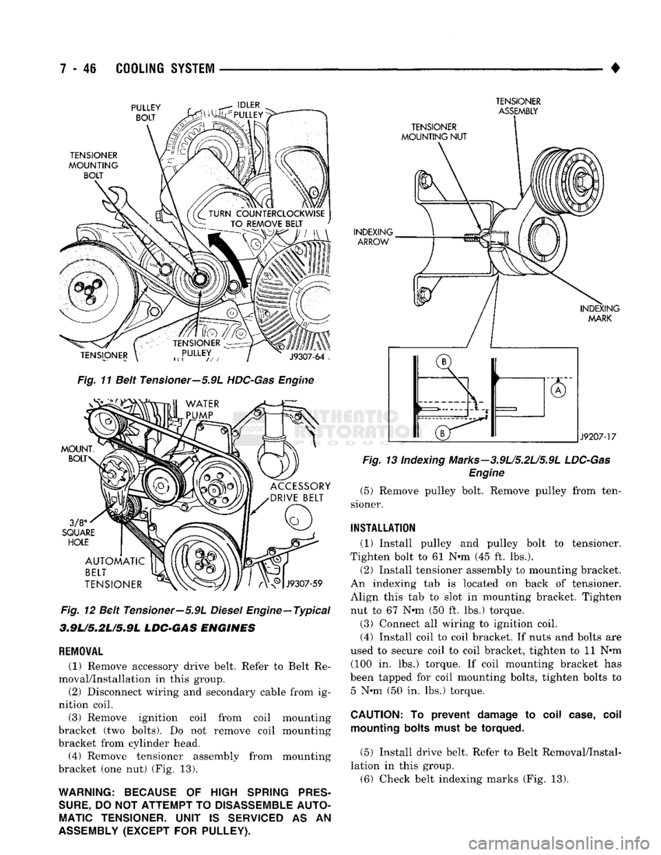
(1) Remove accessory drive belt. Refer to Belt Re
moval/Installation in this group. (2) Disconnect wiring and secondary cable from ig
nition coil.
(3) Remove ignition coil from coil mounting
bracket (two bolts). Do not remove coil mounting
bracket from cylinder head. (4) Remove tensioner assembly from mounting
bracket (one nut) (Fig. 13).
WARNING: BECAUSE
OF
HIGH
SPRING
PRES
SURE,
DO
NOT ATTEMPT
TO
DISASSEMBLE
AUTO
MATIC
TENSIONER.
UNIT
IS
SERVICED
AS AN
ASSEMBLY
(EXCEPT
FOR
PULLEY).
TENSIONER
MOUNTING NUT
INDEXING ARROW
INDEXING MARK
J9207-17
Fig.
13 indexing Marks-3.9L/5.2L/5.9L
LDC-Gas
Engine
(5) Remove pulley bolt. Remove pulley from ten
sioner.
INSTALLATION
(1) Install pulley and pulley bolt to tensioner.
Tighten bolt to 61 Nnn (45 ft. lbs.).
(2) Install tensioner assembly to mounting bracket.
An indexing tab is located on back of tensioner.
Align this tab to slot in mounting bracket. Tighten nut to 67 Nnn (50 ft. lbs.) torque.
(3) Connect all wiring to ignition coil. (4) Install coil to coil bracket. If nuts and bolts are
used to secure coil to coil bracket, tighten to 11 Nnn (100 in. lbs.) torque. If coil mounting bracket has
been tapped for coil mounting bolts, tighten bolts to 5 Nnn (50 in. lbs.) torque.
CAUTION:
To
prevent damage
to
coil case, coil mounting bolts must
be
torqued.
(5) Install drive belt. Refer to Belt Removal/Instal
lation in this group. (6) Check belt indexing marks (Fig. 13).
Page 322 of 1502
•
ELECTRICAL
ELECTRICAL
8A - 1
Group
AUDIO
SYSTEMS
8F
BATTERY/STARTER/GENERATOR
SERVICE
.. 8B
BATTERY/STARTING/CHARGING
SYSTEMS
DIAGNOSTICS
8A
HORNS
8G
IGNITION
SYSTEMS
8D
INSTRUMENT PANEL AND
GAUGES
8E
LAMPS
8L
POWER
LOCKS
8P
INDEX
Group
POWER
MIRRORS
8T
POWER
WINDOWS 8S
REAR
WINDOW DEFOGGER 8N
TURN
SIGNALS
AND HAZARD WARNING
FLASHERS
8J
VEHICLE
SPEED
CONTROL SYSTEM 8H WARNING BUZZER SYSTEM 8U
WINDSHIELD WIPERS AND
WASHERS
8K
WIRING DIAGRAMS 8W
BATTERY/STARTING/CHARGING SYSTEMS DIAGNOSTICS
CONTENTS
page
page
BATTERY TEST
PROCEDURES
2 GENERATOR TEST
PROCEDURES
ON VEHICLE . 13
ENGINE
STARTER MOTOR TEST
PROCEDURES
..9 SPECIFICATIONS 18
GENERAL
INFORMATION 1
GENERAL INFORMATION
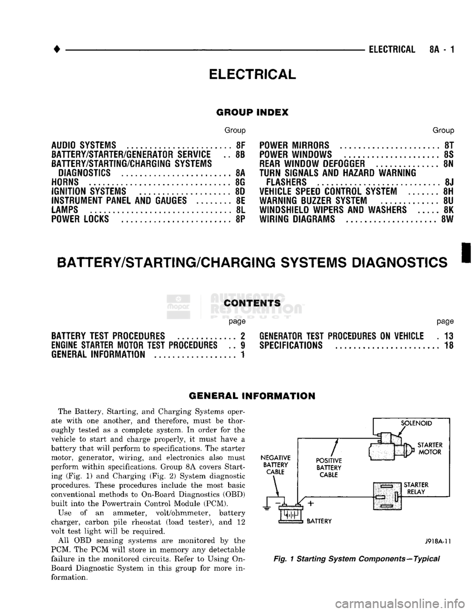
The Battery, Starting, and Charging Systems oper
ate with one another, and therefore, must be thor
oughly tested as a complete system. In order for the
vehicle to start and charge properly, it must have a
battery that will perform to specifications. The starter
motor, generator, wiring, and electronics also must
perform within specifications. Group 8A covers Start ing (Fig. 1) and Charging (Fig. 2) System diagnostic
procedures. These procedures include the most basic
conventional methods to On-Board Diagnostics (OBD)
built into the Powertrain Control Module (PCM).
Use of an ammeter, volt/ohmmeter, battery
charger, carbon pile rheostat (load tester), and 12
volt test light will be required.
All OBD sensing systems are monitored by the
PCM. The PCM will store in memory any detectable
failure in the monitored circuits. Refer to Using On-
Board Diagnostic System in this group for more in formation.
NEGATIVE
BATTERY
CABLE
A
7
POSITIVE
BATTERY
CABLE
BATTERY
J918A-11
Fig.
1 Starting
System
Components—Typical