1993 DODGE TRUCK air condition
[x] Cancel search: air conditionPage 51 of 1502
0
- 32
LUBRICATION
AND
MAINTENANCE
•
Fig.
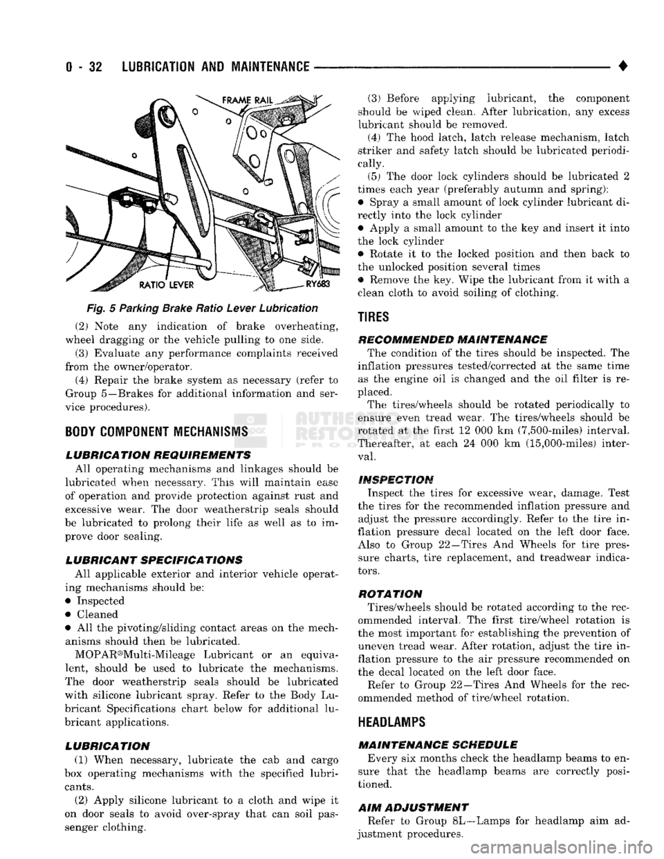
5 Parking Brake Ratio Lever Lubrication (2) Note any indication of brake overheating,
wheel dragging or the vehicle pulling to one side.
(3) Evaluate any performance complaints received
from the owner/operator. (4) Repair the brake system as necessary (refer to
Group 5—Brakes for additional information and ser
vice procedures).
BODY
COMPONENT
MECHANISMS
LUBRICATION REQUIREMENTS
All operating mechanisms and linkages should be
lubricated when necessary. This will maintain ease of operation and provide protection against rust and
excessive wear. The door weatherstrip seals should
be lubricated to prolong their life as well as to im prove door sealing.
LUBRICANT SPECIFICATIONS
All applicable exterior and interior vehicle operat
ing mechanisms should be:
• Inspected • Cleaned
• All the pivoting/sliding contact areas on the mech anisms should then be lubricated.
MOPAR®Multi-Mileage Lubricant or an equiva
lent, should be used to lubricate the mechanisms.
The door weatherstrip seals should be lubricated
with silicone lubricant spray. Refer to the Body Lu
bricant Specifications chart below for additional lu
bricant applications.
LUBRICATION
(1) When necessary, lubricate the cab and cargo
box operating mechanisms with the specified lubri
cants.
(2) Apply silicone lubricant to a cloth and wipe it
on door seals to avoid over-spray that can soil pas
senger clothing. (3) Before applying lubricant, the component
should be wiped clean. After lubrication, any excess
lubricant should be removed.
(4) The hood latch, latch release mechanism, latch
striker and safety latch should be lubricated periodi
cally.
(5) The door lock cylinders should be lubricated 2
times each year (preferably autumn and spring): • Spray a small amount of lock cylinder lubricant di
rectly into the lock cylinder
• Apply a small amount to the key and insert it into
the lock cylinder • Rotate it to the locked position and then back to
the unlocked position several times
• Remove the key. Wipe the lubricant from it with a
clean cloth to avoid soiling of clothing.
TIRES
RECOMMENDED MAINTENANCE
The condition of the tires should be inspected. The
inflation pressures tested/corrected at the same time as the engine oil is changed and the oil filter is re
placed.
The tires/wheels should be rotated periodically to
ensure even tread wear. The tires/wheels should be
rotated at the first 12 000 km (7,500-miles) interval.
Thereafter, at each 24 000 km (15,000-miles) inter
val.
INSPECTION
Inspect the tires for excessive wear, damage. Test
the tires for the recommended inflation pressure and adjust the pressure accordingly. Refer to the tire in
flation pressure decal located on the left door face. Also to Group 22—Tires And Wheels for tire pressure charts, tire replacement, and treadwear indica
tors.
ROTATION
Tires/wheels should be rotated according to the rec
ommended interval. The first tire/wheel rotation is
the most important for establishing the prevention of uneven tread wear. After rotation, adjust the tire in
flation pressure to the air pressure recommended on
the decal located on the left door face.
Refer to Group 22—Tires And Wheels for the rec
ommended method of tire/wheel rotation.
HEADLAMPS
MAINTENANCE SCHEDULE
Every six months check the headlamp beams to en
sure that the headlamp beams are correctly posi
tioned.
AIM
ADJUSTMENT
Refer to Group 8L—Lamps for headlamp aim ad
justment procedures.
Page 56 of 1502
FRONT SUSPENSION
AND
AXLE
2 - 3
FRONT
WHEEL
ALIGNMENT
GENERAL
INFORMATION
Front wheel alignment involves
the
correct posi
tioning
of the
tire contact patch
in
relation
to the
pavement.
The
positioning
is
accomplished through
the suspension
and
steering linkage adjustments.
An
alignment
is
essential
for
efficient steering
and
direc
tional stability.
The
most important factors
of
front
end alignment
are
camber, caster
and toe
position. Routine inspection
of
the front
suspension
and
steering components
is a
good
preventative
maintenance practice.
Inspection
also
helps
to
ensure
safe operation
of the
vehicle.
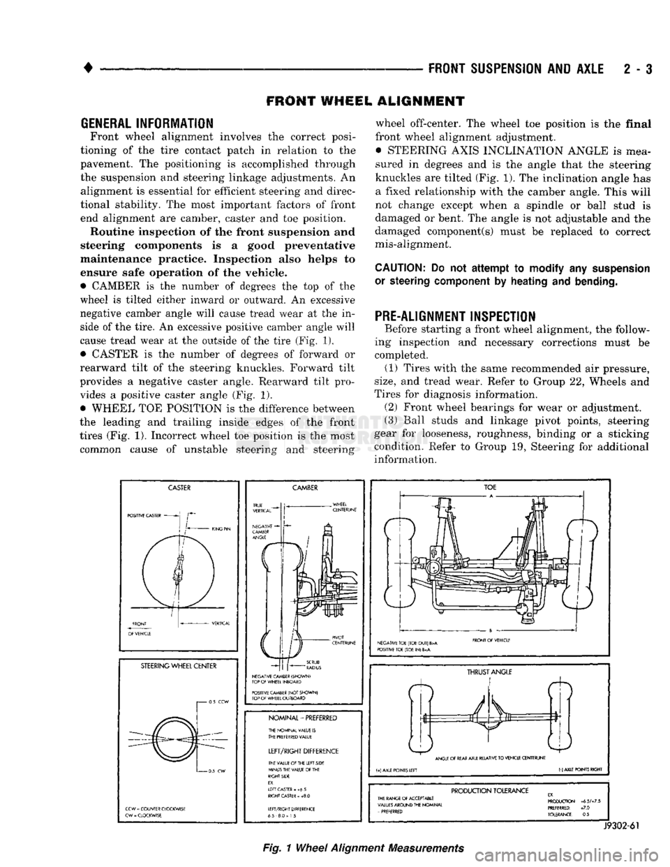
• CAMBER
is the
number
of
degrees
the top of the
wheel
is
tilted either inward
or
outward.
An
excessive
negative camber angle will cause tread wear
at the in
side
of
the tire.
An
excessive positive camber angle will
cause tread wear
at the
outside
of
the tire (Fig.
1),
• CASTER
is the
number
of
degrees
of
forward
or
rearward tilt
of the
steering knuckles. Forward tilt
provides
a
negative caster angle. Rearward tilt pro vides
a
positive caster angle
(Fig. 1).
• WHEEL
TOE
POSITION
is the
difference between
the leading
and
trailing inside edges
of the
front
tires (Fig.
1).
Incorrect wheel
toe
position
is the
most common cause
of
unstable steering
and
steering wheel off-center.
The
wheel
toe
position
is the
final
front wheel alignment adjustment. • STEERING AXIS INCLINATION ANGLE
is
mea
sured
in
degrees
and is the
angle that
the
steering
knuckles
are
tilted (Fig. 1).
The
inclination angle
has
a fixed relationship with
the
camber angle. This will
not change except when
a
spindle
or
ball stud
is
damaged
or
bent.
The
angle
is not
adjustable
and the
damaged component(s) must
be
replaced
to
correct
mis-alignment.
CAUTION:
Do not
attempt to modify
any
suspension
or steering
component
by
heating
and
bending.
PRE-ALIGNMENT INSPECTION
Before starting
a
front wheel alignment,
the
follow
ing inspection
and
necessary corrections must
be
completed.
(1)
Tires with
the
same recommended
air
pressure,
size,
and
tread wear. Refer
to
Group
22,
Wheels
and
Tires
for
diagnosis information. (2) Front wheel bearings
for
wear
or
adjustment.
(3) Ball studs
and
linkage pivot points, steering
gear
for
looseness, roughness, binding
or a
sticking
condition. Refer
to
Group
19,
Steering
for
additional information.
CASTER
POSITIVE CASTER
STEERING
WHEEL CENTER
i 0.5
CCW
0
5
CW
CCW
=
COUNTER CLOCKWISE
CW
-
CLOCKWISE
CAMBER
NEGATIVE CAMBER (SHOWN)
TOP
OF
WHEEL INBOARD
POSITIVE CAMBER
(NOT
SHOWN)
TOP
OF
WHEEL OUTBOARD
NOMINAL-PREFERRED
THE NOMINAL VALUE
IS
THE
PREFERRED
VALUE
LEFT/RIGHT
DIFFERENCE
THE VALUE
Of
THE LEFT SIDE
MINUS THE VALUE
OF
THE
RIGHT SIDE
EX.
If
FT CASTER
- +6 5
RIGHT
CASTER
»
+8.0
LEFT/RIGHT DIFFERENCE
65 8.0
=
1
5
TOE
NEGATIVE TOE (TOE
OUT)
B>A
POSITIVE TOE (TOE
IN) 6
FRONT
Of
VEHICLE
ft
THRUST
ANGLE
ANGLE
OF
REAR
AXLE RELATIVE
TO
VEHICLE CENTERUNE
(+)
AXLE POINTS LEFT
(-)
AXLE POINTS RIGHT
PRODUCTION
TOLERANCE
THE RANGE
Of
ACCEPTABLE
VALUES
AROUND THE NOMINAL
-
PREFERRED PRODUCTION
+6.5A7.5
PREFERRED:
+7.0
TOLERANCE:
0.5
J9302-61
Fig.
1
Wheel
Alignment
Measurements
Page 132 of 1502
•
REAR
SUSPENSION
AND
AXLE
3 - 3
REAR SUSPENSION—2WD
and 4WD
VEHICLES
SPRING
AND
SHOCK DIAGNOSIS
A squeak noise from the shock absorber or spring
bushings can be produced if movement between the
rubber bushings and the metal occurs. This noise can usually be stopped by tightening the attaching nuts.
If the squeak noise persists, inspect for damaged and
worn bushings, and attaching components. Repair as
necessary if any of these conditions exist. The shock absorber bushings do not require any
type of lubrication. Do not lubricate the bushings to reduce bushing noise. Grease or mineral oil-base lu
bricants will deteriorate the bushing rubber. The shock absorbers are not reflllable or adjust
able.
If a malfunction occurs, the shock absorber
must be replaced. To test a shock absorber, hold it in an upright position and force the piston into and out
of the cylinder four or five times. The action through
out each stroke should be smooth and even. The spring eye and shock absorber bushings do not
require any type of lubrication. Do not attempt to stop spring bushing noise by lubricating them.
Grease and mineral oil-base lubricants will deterio
rate the bushing rubber. If the vehicle is used for severe, off-road operation,
the springs should be examined periodically. Check for broken and shifted leafs, loose and missing clips, and broken center bolts.
VEHICLE LOADING
AND
WEIGHT DISTRIBUTION
A vehicle should always be loaded so the vehicle
weight center-line is located immediately forward of
the rear axle. Correct vehicle loading provides proper
front tire-to-road contact. This results in maximum
vehicle handling stability and safety. Refer to Spring and Shock Absorber Diagnosis chart for further in
formation. Incorrect weight distribution should be consid
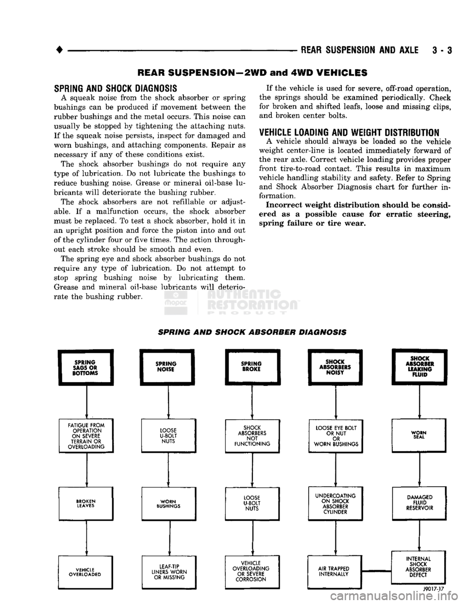
ered as a possible cause for erratic steering, spring failure or tire wear. SPRING AND SHOCK ABSORBER DIAGNOSIS
FATIGUE FROM
OPERATION
ON SEVERE
TERRAIN
OR
OVERLOADING
LOOSE
U-BOLT
NUTS
SHOCK
ABSORBERS
NOT
FUNCTIONING
LOOSE
EYE
BOLT
OR
NUT
OR
WORN BUSHINGS WORN
SEAL
BROKEN
LEAVES
WORN
BUSHINGS
UNDERCOATING
ON SHOCK
ABSORBER
CYLINDER
DAMAGED
FLUID
RESERVOIR
VEHICLE
OVERLOADED LEAF-TIP
LINERS
WORN OR MISSING VEHICLE
OVERLOADING OR SEVERE
CORROSION
AIR TRAPPED
INTERNALLY INTERNAL
SHOCK
ABSORBER
DEFECT
J9017-17
Page 135 of 1502
3
- 6
REAR SUSPENSION
AND
AXLE
•
NUT PIPE
SOCKET
WRENCH
(DRIVER)
FLAT
THREADED
WASHER
ROD
J8917-20
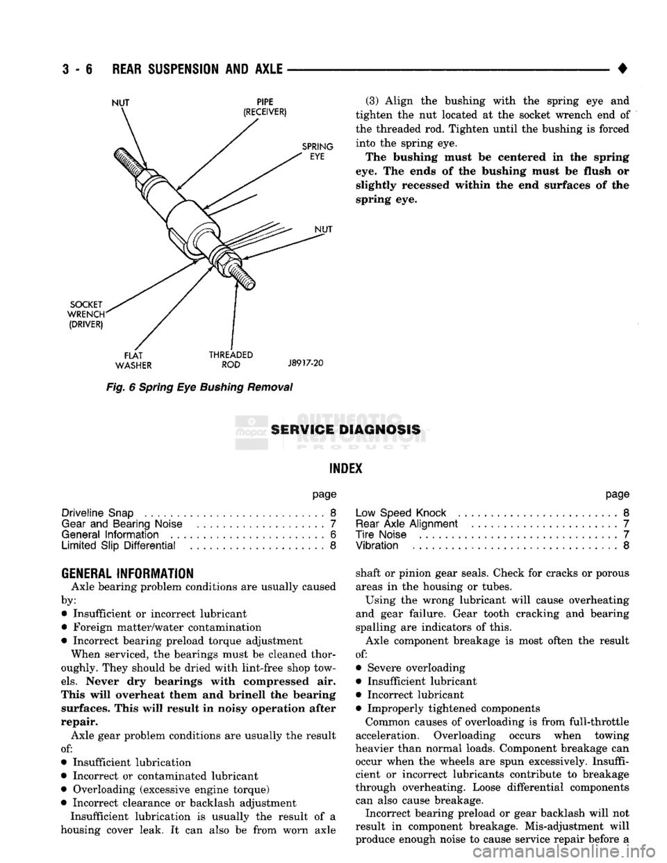
Fig.
6
Spring
Eye
Bushing
Removal
(3) Align
the
bushing with
the
spring
eye and
tighten
the nut
located
at the
socket wrench
end of
the threaded
rod.
Tighten until
the
bushing
is
forced into
the
spring
eye.
The bushing must
be
centered
in the
spring
eye.
The
ends
of the
bushing must
be
flush
or
slightly recessed within
the end
surfaces
of the
spring
eye.
8ERW1GE DIAGNOSIS
INDEX
page
Driveline
Snap
8
Gear
and
Bearing Noise
7
General
Information
6
Limited
Slip
Differential
8
page
Low Speed Knock
.........................
8
Rear
Axle
Alignment
.......................
7
Tire
Noise
7
Vibration
8
GENERAL INFORMATION
Axle bearing problem conditions
are
usually caused
by: • Insufficient
or
incorrect lubricant
• Foreign matter/water contamination
• Incorrect bearing preload torque adjustment When serviced,
the
bearings must
be
cleaned thor
oughly. They should
be
dried with lint-free shop tow
els.
Never
dry
bearings with compressed
air.
This will overheat them
and
brinell
the
bearing surfaces. This will result
in
noisy operation after
repair. Axle gear problem conditions
are
usually
the
result
of:
• Insufficient lubrication
• Incorrect
or
contaminated lubricant
• Overloading (excessive engine torque)
• Incorrect clearance
or
backlash adjustment Insufficient lubrication
is
usually
the
result
of a
housing cover leak.
It can
also
be
from worn axle shaft
or
pinion gear seals. Check
for
cracks
or
porous
areas
in the
housing
or
tubes.
Using
the
wrong lubricant will cause overheating
and gear failure. Gear tooth cracking
and
bearing
spalling
are
indicators
of
this.
Axle component breakage
is
most often
the
result
of:
• Severe overloading
• Insufficient lubricant
• Incorrect lubricant • Improperly tightened components
Common causes
of
overloading
is
from full-throttle
acceleration. Overloading occurs when towing
heavier than normal loads. Component breakage
can
occur when
the
wheels
are
spun excessively. Insuffi
cient
or
incorrect lubricants contribute
to
breakage
through overheating. Loose differential components can also cause breakage. Incorrect bearing preload
or
gear backlash will
not
result
in
component breakage. Mis-adjustment will
produce enough noise
to
cause service repair before
a
Page 137 of 1502
3
- 8
REAR SUSPENSION
AND
AXLE
• level. Where axle bearing damage is slight, the noise
is usually not noticeable at speeds above 30 mph.
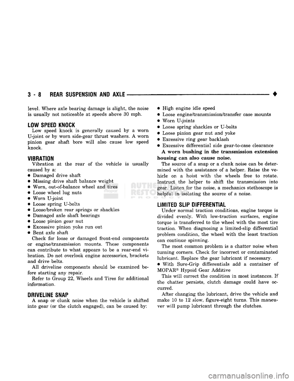
LOW SPEED KNOCK
Low speed knock is generally caused by a worn
U-joint or by worn side-gear thrust washers. A worn
pinion gear shaft bore will also cause low speed knock.
VIBRATION
Vibration at the rear of the vehicle is usually
caused by a:
• Damaged drive shaft
• Missing drive shaft balance weight
• Worn, out-of-balance wheel and tires
• Loose wheel lug nuts
• Worn U-joint • Loose spring U-bolts
• Loose/broken rear springs or shackles
• Damaged axle shaft bearings
• Loose pinion gear nut
• Excessive pinion yoke run out
• Bent axle shaft Check for loose or damaged front-end components
or engine/transmission mounts. These components
can contribute to what appears to be a rear-end vi
bration. Do not overlook engine accessories, brackets and drive belts. All driveline components should be examined be
fore starting any repair. Refer to Group 22, Wheels and Tires for additional
information.
DRIVELINE SNAP
A snap or clunk noise when the vehicle is shifted
into gear (or the clutch engaged), can be caused by: • High engine idle speed
• Loose engine/transmission/transfer case mounts
9
Worn U-joints
• Loose spring shackles or U-bolts
• Loose pinion gear nut and yoke
• Excessive ring gear backlash
• Excessive differential side gear-to-case clearance A worn bushing in the transmission extension
housing can also cause noise. The source of a snap or a clunk noise can be deter
mined with the assistance of a helper. Raise the ve
hicle on a hoist with the wheels free to rotate. Instruct the helper to shift the transmission into gear. Listen for the noise, a mechanics stethoscope is
helpful in isolating the source of a noise.
LIMITED
SLIP DIFFERENTIAL
Under normal traction conditions, engine torque is
divided evenly. With low-traction surfaces, engine
torque is transferred to the wheel with the most tire
traction. When diagnosing a limited-slip differential
problem condition, the wheel with the least traction can continue spinning. The most common problem is a chatter noise when
turning corners. Check for incorrect or contaminated lubricant. Replace the gear lubricant if necessary.
• With Sure-Grip differentials add a container of
MOPAR® Hypoid Gear Additive This will correct the condition in most instances. If
the chatter persists, clutch damage could have oc curred. After changing the lubricant, drive the vehicle and
make 10 to 12 slow, figure-eight turns. This maneu
ver will pump lubricant through the clutches.
Page 138 of 1502
REAR
SUSPENSION
AND
AXLE
3 - 9
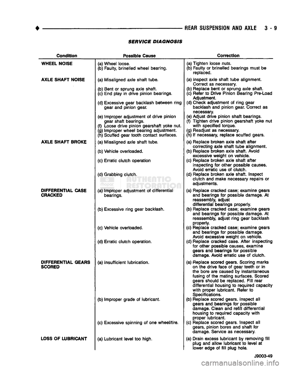
SERVICE DIAGNOSIS
Condition
Possible
Cause
Correction
WHEEL
NOISE
AXLE
SHAFT
NOISE
AXLE
SHAFT
BROKE
DIFFERENTIAL
CASE
CRACKED
DIFFERENTIAL
GEARS
SCORED
LOSS
OF
LUBRICANT
(a) Wheel loose.
(b) Faulty, brinelled
wheel
bearing.
(a) Misaligned axle shaft tube.
(b) Bent or sprung axle shaft. (c) End play in drive pinion bearings.
(d) Excessive gear backlash
between
ring
gear
and pinion gear.
(e) Improper adjustment of drive pinion
gear
shaft bearings.
(f) Loose drive pinion gearshaft yoke nut.
(g) Improper
wheel
bearing adjustment. (h) Scuffed gear tooth contact surfaces.
(a) Misaligned axle shaft tube.
(b) Vehicle overloaded.
(c) Erratic clutch operation
(d) Grabbing clutch.
(a) Improper adjustment of
differential
bearings.
(b) Excessive ring gear backlash.
(c) Vehicle overloaded. (d) Erratic clutch operation.
(a) Insufficient lubrication.
(b) Improper grade of lubricant.
(c) Excessive spinning of one
wheel/tire.
(a) Lubricant
level
too high. (a) Tighten loose nuts.
(b) Faulty or brinelled bearings must be
replaced.
(a) Inspect axle shaft
tube
alignment. Correct as necessary.
(b) Replace bent or sprung axle shaft.
(c) Refer to Drive Pinion Bearing Pre-Load Adjustment.
(d) Check adjustment of ring gear
backlash
and pinion gear. Correct as
necessary.
(e) Adjust drive pinion shaft bearings.
(f) Tighten drive pinion gearshaft yoke nut
with
specified torque.
(g) Readjust as necessary.
(h) If necessary, replace scuffed gears.
(a) Replace broken axle shaft
after
correcting axle shaft
tube
alignment.
(b) Replace broken axle shaft. Avoid
excessive
weight on vehicle.
(c) Replace broken axle shaft
after
inspecting for other possible
causes.
Avoid
erratic
use of clutch.
(d) Replace broken axle shaft. Inspect clutch and make necessary repairs or adjustments.
(a) Replace cracked case; examine gears and bearings for possible damage. At
reassembly,
adjust
differential
bearings properly.
(b) Replace cracked case; examine gears and bearings for possible damage. At
reassembly,
adjust ring gear backlash properly.
(c) Replace cracked case; examine gears and bearings for possible damage.
Avoid
excessive weight on vehicle.
(d) Replace cracked case.
After
inspecting for other possible
causes,
examine
gears
and bearings for possible
damage.
Avoid
erratic
use of clutch.
(a) Replace scored gears. Scoring marks
on
the drive face of gear
teeth
or in
the bore are caused by instantaneous
fusing
of the mating surfaces. Scored
gears
should be replaced.
Fill
rear
differential
housing to
required
capacity
with
proper lubricant. Refer to
Specifications.
(b) Replace scored gears. Inspect all
gears
and bearings for possible
damage.
Clean and
refill
differential
housing
to
required
capacity
with
proper lubricant.
(c) Replace scored gears. Inspect all
gears,
pinion bores and shaft for
damage.
Service as necessary.
(a) Drain excess lubricant by removing
fill
plug and allow lubricant to
level
at lower edge of
fill
plug hole.
J9003-49
Page 139 of 1502
3-10
REAR SUSPENSION
AND
AXLE
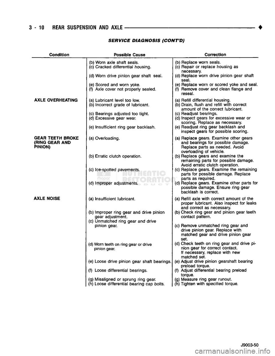
SERVICE DIAGNOSIS (CONT'D)
Condition
Possible
Cause
Correction
AXLE OVERHEATING
GEAR TEETH BROKE
(RING GEAR
AND
PINION)
AXLE NOISE
(b) Worn axle
shaft
seals.
(c) Cracked
differential
housing.
(d) Worn
drive
pinion
gear
shaft
seal.
(e) Scored and worn yoke.
(f) Axle cover not
properly
sealed.
(a)
Lubricant
level
too low. (b)
Incorrect
grade of
lubricant.
(c) Bearings
adjusted
too
tight.
(d) Excessive gear wear.
(e)
Insufficient
ring
gear backlash,
(a) Overloading.
(b)
Erratic
clutch
operation.
(c) Ice-spotted pavements.
(d) Improper adjustments.
(a)
Insufficient
lubricant.
(b) Improper
ring
gear and
drive
pinion
gear
adjustment.
(c) Unmatched
ring
gear and
drive
pinion
gear.
(d) Worn
teeth
on
ring
gear or
drive
pinion
gear.
(e) Loose
drive
pinion
gear
shaft
bearings.
(f) Loose
differential
bearings.
(g) Misaligned or sprung
ring
gear.
(h) Loose
differential
bearing cap bolts. (b) Replace worn
seals.
(c) Repair or replace housing as
necessary.
(d) Replace worn
drive
pinion
gear
shaft
seal.
(e) Replace worn or scored yoke and seal.
(f) Remove cover and clean flange and reseal.
(a)
Refill
differential
housing. (b) Drain,
flush
and
refill
with
correct
amount of the
correct
lubricant.
(c) Readjust bearings.
(d) Inspect gears for excessive wear or scoring. Replace as necessary.
(e) Readjust
ring
gear backlash and inspect gears for possible scoring.
(a) Replace gears. Examine
other
gears and bearings for possible damage. Replace parts as needed. Avoid
overloading of vehicle.
(b) Replace gears and examine the remaining parts for possible damage.
Avoid
erratic
clutch
operation.
(c) Replace gears. Examine the remaining parts for possible damage. Replace
parts as required.
(d) Replace gears. Examine
other
parts for possible damage. Ensure
ring
gear
backlash is
correct.
(a)
Refill
axle
with
correct
amount of the proper
lubricant.
Also inspect for leaks
and
correct
as necessary.
(b) Check
ring
gear and
pinion
gear
teeth
contact
pattern.
(c) Remove unmatched
ring
gear and
drive
pinion
gear. Replace
with
matched gear and
drive
pinion
gear
set.
(d) Check
teeth
on
ring
gear and
drive
pi nion gear for
correct
contact.
If necessary, replace
with
new
matched set.
(e) Adjust
drive
pinion
gearshaft bearing preload
torque.
(f) Adjust
differential
bearing preload
torque.
(g) Measure
ring
gear
runout.
(h) Tighten
with
specified
torque.
J9003-50
Page 191 of 1502
5
- 4
BRAKES
• (3) During road test, make normal and firm brake
stops in 25-40 mph (40-64 Km/h) range. Note faulty
brake operation such as pull, grab, drag, noise, low
pedal, etc.
(4) Inspect suspect brake components and refer to
problem diagnosis information for causes of various
brake conditions.
COMPONENT
INSPECTION
Fluid leak points and dragging brake units can usu
ally be located without removing any components. The
area around a leak point will be wet with fluid. The
components at a dragging brake unit (wheel, tire, rotor)
will be quite warm or hot to the touch.
Other brake problem conditions will require compo
nent removal for proper inspection. Raise the vehicle and remove the necessary wheels for better visual ac
cess.
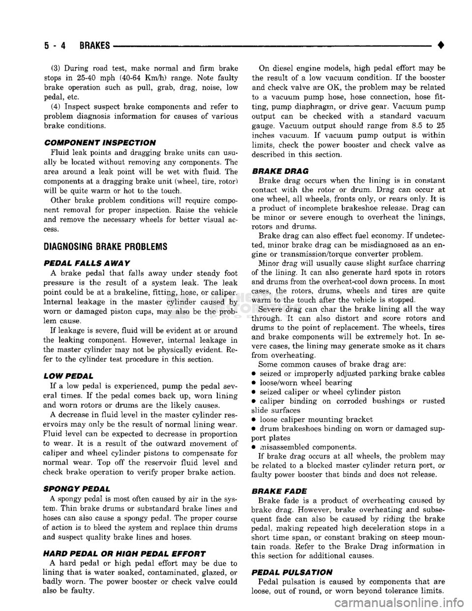
DIAGNOSING BRAKE
PROBLEMS
PEDAL FALLS
AWAY
A
brake pedal that falls away under steady foot
pressure is the result of a system leak. The leak
point could be at a brakeline, fitting, hose, or caliper. Internal leakage in the master cylinder caused by
worn or damaged piston cups, may also be the prob lem cause.
If leakage is severe, fluid will be evident at or around
the leaking component. However, internal leakage in
the master cylinder may not be physically evident. Re fer to the cylinder test procedure in this section.
LOW PEDAL
If a low pedal is experienced, pump the pedal sev
eral times. If the pedal comes back up, worn lining
and worn rotors or drums are the likely causes.
A decrease in fluid level in the master cylinder res
ervoirs may only be the result of normal lining wear.
Fluid level can be expected to decrease in proportion to wear. It is a result of the outward movement of
caliper and wheel cylinder pistons to compensate for
normal wear. Top off the reservoir fluid level and
check brake operation to verify proper brake action.
SPONGY PEDAL. A spongy pedal is most often caused by air in the sys
tem. Thin brake drums or substandard brake lines and
hoses can also cause a spongy pedal. The proper course
of action is to bleed the system and replace thin drums and suspect quality brake lines and hoses.
HARD PEDAL
OR
HIGH
PEDAL
EFFORT
A hard pedal or high pedal effort may be due to
lining that is water soaked, contaminated, glazed, or
badly worn. The power booster or check valve could also be faulty. On diesel engine models, high pedal effort may be
the result of a low vacuum condition. If the booster and check valve are OK, the problem may be related
to a vacuum pump hose, hose connection, hose fit
ting, pump diaphragm, or drive gear. Vacuum pump output can be checked with a standard vacuum
gauge. Vacuum output should range from 8.5 to 25 inches vacuum. If vacuum pump output is within
limits,
check the power booster and check valve as
described in this section.
BRAKE DRAG
Brake drag occurs when the lining is in constant
contact with the rotor or drum. Drag can occur at
one wheel, all wheels, fronts only, or rears only. It is a product of incomplete brakeshoe release. Drag can
be minor or severe enough to overheat the linings,
rotors and drums.
Brake drag can also effect fuel economy. If undetec
ted, minor brake drag can be misdiagnosed as an en gine or transmission/torque converter problem.
Minor drag will usually cause slight surface charring
of the lining. It can also generate hard spots in rotors and drums from the overheat-cool down process. In most
cases,
the rotors, drums, wheels and tires are quite
warm to the touch after the vehicle is stopped.
Severe drag can char the brake lining all the way
through. It can also distort and score rotors and drums to the point of replacement. The wheels, tires and brake components will be extremely hot. In se
vere cases, the lining may generate smoke as it chars
from overheating.
Some common causes of brake drag are:
• seized or improperly adjusted parking brake cables
• loose/worn wheel bearing
• seized caliper or wheel cylinder piston
• caliper binding on corroded bushings or rusted
slide surfaces
• loose caliper mounting bracket
• drum brakeshoes binding on worn or damaged sup
port plates
• misassembled components. If brake drag occurs at all wheels, the problem may
be related to a blocked master cylinder return port, or faulty power booster that binds and does not release.
BRAKE FADE
Brake fade is a product of overheating caused by
brake drag. However, brake overheating and subse quent fade can also be caused by riding the brake
pedal, making repeated high deceleration stops in a short time span, or constant braking on steep moun
tain roads. Refer to the Brake Drag information in
this section for additional causes.
PEDAL
PULSA
TION
Pedal pulsation is caused by components that are
loose, out of round, or worn beyond tolerance limits.