1993 DODGE TRUCK air condition
[x] Cancel search: air conditionPage 192 of 1502

•
BRAKES
5 - 5 Disc brake rotors with excessive lateral runout or
thickness variation, or out of round brake drums are
the primary causes of pulsation. Other causes are loose
wheel bearings or calipers and worn, damaged tires.
PULL A
front pull condition could be the result of con
taminated lining in one caliper, seized caliper piston,
binding caliper, loose caliper, loose or corroded slide
pins,
improper brakeshoes, or a damaged rotor.
A worn, damaged wheel bearing or suspension compo
nent are further causes of pull. A damaged front tire (bruised, ply separation) can also cause pull.
A common and frequently misdiagnosed pull condi
tion is where direction of pull changes after a few
stops.
The cause is a combination of brake drag fol
lowed by fade at one of the brake units.
As the dragging brake overheats, efficiency is so
reduced that fade occurs. Since the opposite brake
unit is still functioning normally, its braking effect is
magnified. This causes pull to switch direction in fa
vor of the normally functioning brake unit.
When diagnosing a change in pull condition, re
member that pull will return to the original direction
if the dragging brake unit is allowed to cool down (and is not seriously damaged).
REAR BRAKE GRAB
OR
PULL
Rear grab or pull is usually caused by an improperly
adjusted or seized parking brake cable, contaminated
lining, bent or binding shoes and support plates, or im
properly assembled components. This is particularly
true when only one rear wheel is involved. However,
when both rear wheels are affected, the master cylinder or proportioning valve could be at fault.
BRAKES
DO NOT
HOLD
AFTER
DRIVING
THROUGH
DEEP
WATER
PUDDLES
This condition is generally caused by water soaked
lining. If the lining is only wet, it can be dried by driv
ing with the brakes very lightly applied for a few min
utes.
However, if the lining is thoroughly wet and dirty,
disassembly and cleaning will be necessary.
BRAKE NOISE
Squeak/Squeal
Brake squeak or squeal may be due to linings that
are wet or contaminated with brake fluid, grease, or oil. Glazed linings and rotors with hard spots can also con
tribute to squeak. Dirt and foreign material embedded in the brake lining can also cause squeak/squeal.
A very loud squeak or squeal is frequently a sign of
severely worn brake lining. If the lining has worn
through to the brakeshoes in spots, metal-to-metal con
tact occurs. If the condition is allowed to continue, ro tors can become so scored that replacement is necessary.
Thump/Clunk
Thumping or clunk noises during braking are fre
quently not caused by brake components. In many
cases,
such noises are caused by loose or damaged steering, suspension, or engine components. How
ever, calipers that bind on the slide pins, or slide sur
faces,
can generate a thump or clunk noise. Worn
out, improperly adjusted, or improperly assembled
rear brakeshoes can also produce a thump noise.
Chatter
Brake chatter is usually caused by loose or worn
components, or glazed/burnt lining. Rotors with hard
spots can also contribute to chatter. Additional
causes of chatter are out of tolerance rotors, brake
lining not securely attached to the shoes, loose wheel
bearings and contaminated brake lining.
Brakelining Contamination Brakelining contamination is usually a product of
leaking calipers or wheel cylinders, driving through
deep water puddles, or lining that has become cov
ered with grease and grit during repair.
Wheel and
Tire
Problems Some conditions attributed to brake components
may actually be caused by a wheel or tire problem.
A damaged wheel can cause shudder, vibration and
pull. A worn or damaged tire can also cause pull.
Severely worn tires with very little tread left can
produce a grab-like condition as the tire loses and re covers traction. Flat-spotted tires can cause vibration and wheel
tramp and generate shudder during brake operation. A tire with internal damage such as a severe
bruise or ply separation can cause pull and vibration.
MASTER
CYLINDER/POWER BOOSTER TEST
(1) Start engine and check booster vacuum hose
connections. Hissing noise indicates a vacuum leak. Correct any leaks before proceeding. (2) Stop engine and shift transmission into Neu
tral (3) Pump brake pedal until all vacuum reserve in
booster is depleted. (4) Press and hold brake pedal under light foot
pressure. (a) If pedal holds firm, proceed to step (5).
(b) If pedal does not hold firm and falls away,
master cylinder is faulty (internal leakage). (5) Start engine and note pedal action. (a) If pedal falls away slightly under light foot
pressure then holds firm, proceed to step (6). (b) If pedal is effort is high, or no pedal action is
discernible, power booster or vacuum check valve is
faulty. Install known good check valve and repeat steps (2) through (5).
Page 193 of 1502
5
- 6
BRAKES
• (c) On diesel models, vacuum pump hose or
pump component may have malfunctioned. Check
pump output with vacuum gauge and repair as necessary. Refer to service procedures in Power
Booster/Vacuum Pump section.
(6) Rebuild booster vacuum reserve as follows: Re
lease brake pedal. Increase engine speed to 1500
rpm, close throttle and immediately turn off ignition. (7) Wait a minimum of 90 seconds and try brake ac
tion again. Booster should provide two or more vacuum assisted pedal applications. If vacuum assist is not pro
vided, perform booster and check valve vacuum tests.
Also check vacuum output on diesel models.
POWER
BOOSTER
CHECK
VALVE
TEST
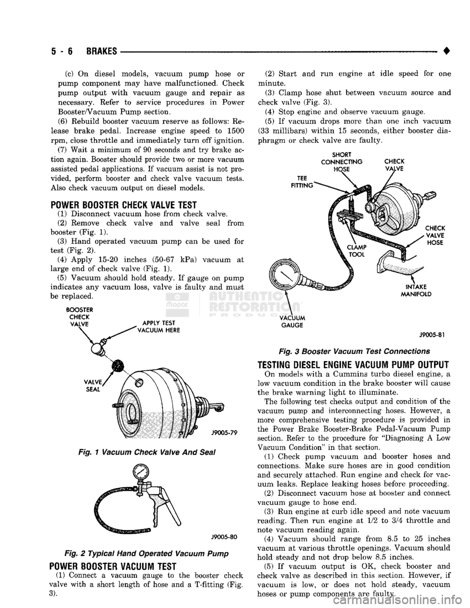
(1) Disconnect vacuum hose from check valve.
(2) Remove check valve and valve seal from
booster (Fig. 1). (3) Hand operated vacuum pump can be used for
test (Fig. 2). (4) Apply 15-20 inches (50-67 kPa) vacuum at
large end of check valve (Fig. 1). (5) Vacuum should hold steady. If gauge on pump
indicates any vacuum loss, valve is faulty and must
be replaced.
BOOSTER
CHECK
VALVE
APPLY
TEST
\
VACUUM
HERE
Fig.
1
Vacuum
Check
Vaive
And
Seal
J9005-80
Fig.
2 Typical
Hand
Operated
Vacuum
Pump
POWER
BOOSTER
VACUUM
TEST
(1) Connect a vacuum gauge to the booster check
valve with a short length of hose and a T-fitting (Fig.
3).
(2) Start and run engine at idle speed for one
minute.
(3) Clamp hose shut between vacuum source and
check valve (Fig. 3).
(4) Stop engine and observe vacuum gauge.
(5) If vacuum drops more than one inch vacuum
(33 millibars) within 15 seconds, either booster dia
phragm or check valve are faulty.
SHORT
CONNECTING
CHECK
VACUUM
GAUGE
J9005-81
Fig.
3
Booster
Vacuum
Test
Connections
TESTING
DIESEL
ENGINE
VACUUM
PUMP
OUTPUT
On models with a Cummins turbo diesel engine, a
low vacuum condition in the brake booster will cause
the brake warning light to illuminate. The following test checks output and condition of the
vacuum pump and interconnecting hoses. However, a
more comprehensive testing procedure is provided in
the Power Brake Booster-Brake Pedal-Vacuum Pump section. Refer to the procedure for "Diagnosing A Low
Vacuum Condition" in that section. (1) Check pump vacuum and booster hoses and
connections. Make sure hoses are in good condition and securely attached. Run engine and check for vac
uum leaks. Replace leaking hoses before proceeding. (2) Disconnect vacuum hose at booster and connect
vacuum gauge to hose end. (3) Run engine at curb idle speed and note vacuum
reading. Then run engine at 1/2 to 3/4 throttle and
note vacuum reading again. (4) Vacuum should range from 8.5 to 25 inches
vacuum at various throttle openings. Vacuum should
hold steady and not drop below 8.5 inches. (5) If vacuum output is OK, check booster and
check valve as described in this section. However, if
vacuum is low, or does not hold steady, vacuum
hoses or pump components are faulty.
Page 196 of 1502
BRAKES
i - 9
Fig.
4 Metering
Valve
Hold
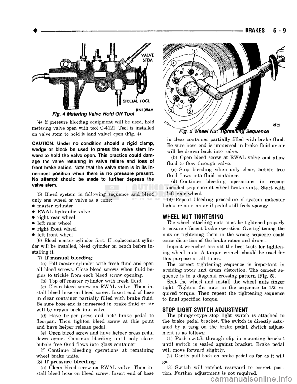
Off Tool (4) If pressure bleeding equipment will be used, hold
metering valve open with tool C-4121. Tool is installed on valve stem to hold it (and valve) open (Fig. 4).
CAUTION:
Under
no
condition should
a
rigid clamp,
wedge
or
block
be
used
to
press
the
valve stem
in
ward
to
hold
the
valve open. This
practice
could dam
age
the
valve resulting
in
valve
failure and
loss
of
front
brake action. Note
that the
valve stem
is in its in
nermost position when
there
is no
pressure present.
No
attempt
should
be
made
to further
depress
the
valve stem.
(5) Bleed system in following sequence and bleed
only one wheel or valve at a time:
• master cylinder • RWAL hydraulic valve
• right rear wheel
• left rear wheel
• right front wheel • left front wheel (6) Bleed master cylinder first. If replacement cylin
der will be installed, bleed cylinder on bench before in stalling it.
(7) If manual bleeding: (a) Fill master cylinder with fresh fluid and open
all bleed screws. Close bleed screws when fluid be
gins to trickle from each bleed screw opening. (b) Top off master cylinder with fresh fluid.
(c) Clean bleed screw on RWAL valve. Then in
stall bleed hose on bleed screw. Insert end of hose
in clear container partially filled with brake fluid.
Be sure hose end is immersed in brake fluid or air
will be drawn back into valve.
(d) Have helper press and hold brake pedal to
floorpan. Then tighten bleed screw at this point and have helper release pedal.
(e) Open bleed screw and have helper press pedal
down again. Continue bleeding until only clear,
bubble free fluid flows into glass container. (f) Continue bleeding operations at remaining
wheel brake units.
(8) If pressure bleeding: (a) Clean bleed screw on RWAL valve. Then in
stall bleed hose on bleed screw. Insert end of hose in clear container partially filled with brake fluid.
Be sure hose end is immersed in brake fluid or air
will be drawn back into valve.
(b) Open bleed screw at RWAL valve and allow
fluid to flow through valve.
(c) Stop bleeding when only clear, bubble free
fluid flows into fluid container.
(d) Continue bleeding operations in recom
mended sequence at wheel brake units. Start with
left rear wheel.
(9) Repeat bleeding procedure if system indicator
lights remain on or if pedal still feels spongy.
WHEEL
NUT
TIGHTENING
The wheel attaching nuts must be tightened properly
to ensure efficient brake operation. Overtightening the nuts or tightening them in the wrong sequence could
cause distortion of the brake rotors and drums.
Impact wrenches are not the best tools for tighten
ing wheel nuts. A torque wrench should be used for
this purpose at all times.
The correct tightening sequence is important in
avoiding rotor and drum distortion. The correct se
quence is in a diagonal crossing pattern (Fig. 5). Seat the wheel and install the wheel nuts finger
tight. Tighten the nuts in the sequence to 1/2 re quired torque. Then repeat the tightening sequence
to final specified torque.
STOP
LIGHT SWITCH ADJUSTMENT
The plunger-type stop light switch is attached to
the brake pedal bracket. The switch is directly actu ated by a tang on the brake pedal. Switch adjust
ment is as follows: (1) Push switch through clip in mounting bracket
until switch is sealed against bracket. Brake pedal
will move forward slightly.
(2) Gently pull back on brake pedal as far as it will
go.
(3) Switch will ratchet rearward to correct posi
tion. Further adjustment is not required.
Page 199 of 1502
i - 12
BRAKES
•
Fig.
6 integral Cylinder
Components
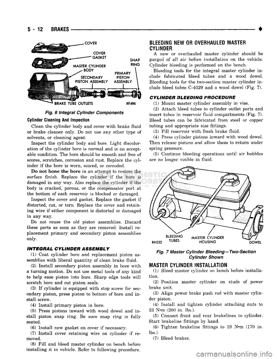
Cylinder Cleaning And Inspection Clean the cylinder body and cover with brake fluid
or brake cleaner only. Do not use any other type of solvents, or cleaning agent. Inspect the cylinder body and bore. Light discolor
ation of the cylinder bore is normal and is an accept
able condition. The bore should be smooth and free of
scores, scratches, corrosion and rust. Replace the cyl
inder if the bore is worn, scored, or corroded.
Do not hone the bore in an attempt to restore the
surface finish. Replace the cylinder if the bore is
damaged in any way. Also replace the cylinder if the
body is cracked, porous, or the compensator port at
the bottom of each reservoir is blocked or damaged.
Inspect the cover and gasket. Replace the gasket if
distorted, cut, or torn. Replace the cover and retain
ing wire if either component is distorted or damaged
in any way.
Do not reuse the old piston assemblies. Discard
these parts as soon as they are removed. Install re
placement primary and secondary piston assemblies
only.
INTEGRAL
CYLINDER ASSEMBLY
(1) Coat cylinder bore and replacement piston as
semblies with liberal quantity of clean brake fluid.
(2) Install secondary piston assembly in bore with
a turning motion. Do not use metal tools of any kind
to help ease piston into bore. Sharp edge tools will
scratch bore and cut piston seals.
(3) If cylinder is equipped with stop screw for sec
ondary piston, press piston to bottom of bore and in
stall screw.
(4) Install primary piston in bore.
(5) Press pistons inward with wood dowel and in
stall piston snap ring. Be sure snap ring is fully
seated.
(6) Install new gasket on cover if necessary.
(7) Install cover retaining wire on cylinder if re
moved. (8) Fill and bleed master cylinder on bench before
installing it in vehicle. Refer to following procedure.
BLEEDING
NEW
OR
OVERHAULED MASTER
CYLINDER
A new or overhauled master cylinder should be
purged of all air before installation on the vehicle. Cylinder bleeding is performed on the bench. Bleeding tools for the integral master cylinder in
clude fabricated bleed tubes and a wood dowel.
Bleeding tools for the two-section master cylinder in clude bleed tubes C-4029 and a wood dowel (Fig. 7).
CYLINDER BLEEDING PROCEDURE
(1) Mount master cylinder assembly in vise.
(2) Attach bleed tubes to cylinder outlet ports and
insert tubes in reservoir fluid compartments (Fig. 7).
Bleed tubes can be fabricated from steel or copper
tubing and appropriate size fittings.
(3) Fill reservoir with fresh brake fluid. (4) Press cylinder pistons inward with wood dowel.
Then release pistons and allow them to return under spring pressure.
(5) Continue bleeding operations until air bubbles
are no longer visible in fluid.
Fig.
7 Master Cylinder
Bleeding—
Two-Section
Cylinder
Shown
MASTER
CYLINDER INSTALLATION
(1) Bleed master cylinder on bench before installa
tion. (2) Position master cylinder on studs of power
brake unit. (3) Align power brake push rod with master cylin
der piston. (4) Install and tighten cylinder attaching nuts to
23 N-m (200 in. lbs.). (5) Connect front and rear brakelines to cylinder.
Start brakeline fittings by hand. (6) Tighten brakeline fittings to 19 N«m (170 in.
lbs.).
(7) Bleed brakes.
Page 200 of 1502
•
BRAKES
5 - 13
COMBINATION VALVE OPERATION
METERING (HOLD-OFF) VALVE The metering valve is used to balance brake action
between the front disc and rear drum brakes. The
valve meters (holds-off) full apply pressure to the front disc brakes until the rear brakeshoes are in full
contact with the drums.
The valve is designed to maintain front brake fluid
pressure at 3-30 psi until the hold-off limit of 117 psi is reached. At this point, the metering valve opens completely permitting full fluid apply pressure to the
front disc brakes.
PRESSURE DIFFERENTIAL SWITCH AND VALVE The pressure differential switch is connected to the
brake warning light. The switch is triggered by movement of the switch valve. The purpose of the switch is to monitor fluid pressure in the separate
front/rear brake hydraulic circuits.
A decrease or loss of fluid pressure in either hy
draulic circuit will cause the switch valve to shuttle
forward or rearward in response to a pressure differ ential.
Movement of the switch valve will push the switch
plunger upward. This closes the switch internal con tacts completing the electrical circuit to the warning light. The switch valve will remain in an actuated
position until repair restores system pressures to nor mal levels.
COMBINATION VALVE TESTING
TESTING METERING VALVE Metering valve operation can be checked visually
and with the aid of a helper.
Observe the metering valve stem while a helper
applies and releases the brakes. If the valve is oper
ating correctly, the stem will extend slightly when
the brakes are applied and retract when the brakes are released.
If the valve is faulty, replace the entire combina
tion valve as an assembly.
TESTING PRESSURE DIFFERENTIAL SWITCH (1) Have helper sit in drivers seat to observe brake
warning light and to operate brake pedal.
(2) Raise vehicle on hoist.
(3) Connect bleed hose to left or right rear wheel
cylinder. Then immerse hose end in glass jar par
tially filled with brake fluid.
(4) Have helper press and hold brake pedal all the
way down and observe warning light.
(a) If warning light illuminates, switch is operat
ing correctly. (b) If light fails to illuminate, check circuit fuse,
bulb and wiring. Repair as necessary and repeat test steps (3) and (4). (5) If warning light still fails to illuminate, check
brakelight and park brake switches (and wiring) with test lamp. Repair or replace parts as necessary and test differential pressure switch operation again.
(6) If warning light still does not illuminate,
switch is faulty. Replace combination valve, bleed
brakes and verify proper switch and valve operation.
COMBINATION VALVE REMOVAL/INSTALLATION
VALVE REMOVAL (1) Raise vehicle on hoist.
(2) Mark or tag brake lines connected to valve for
assembly reference.
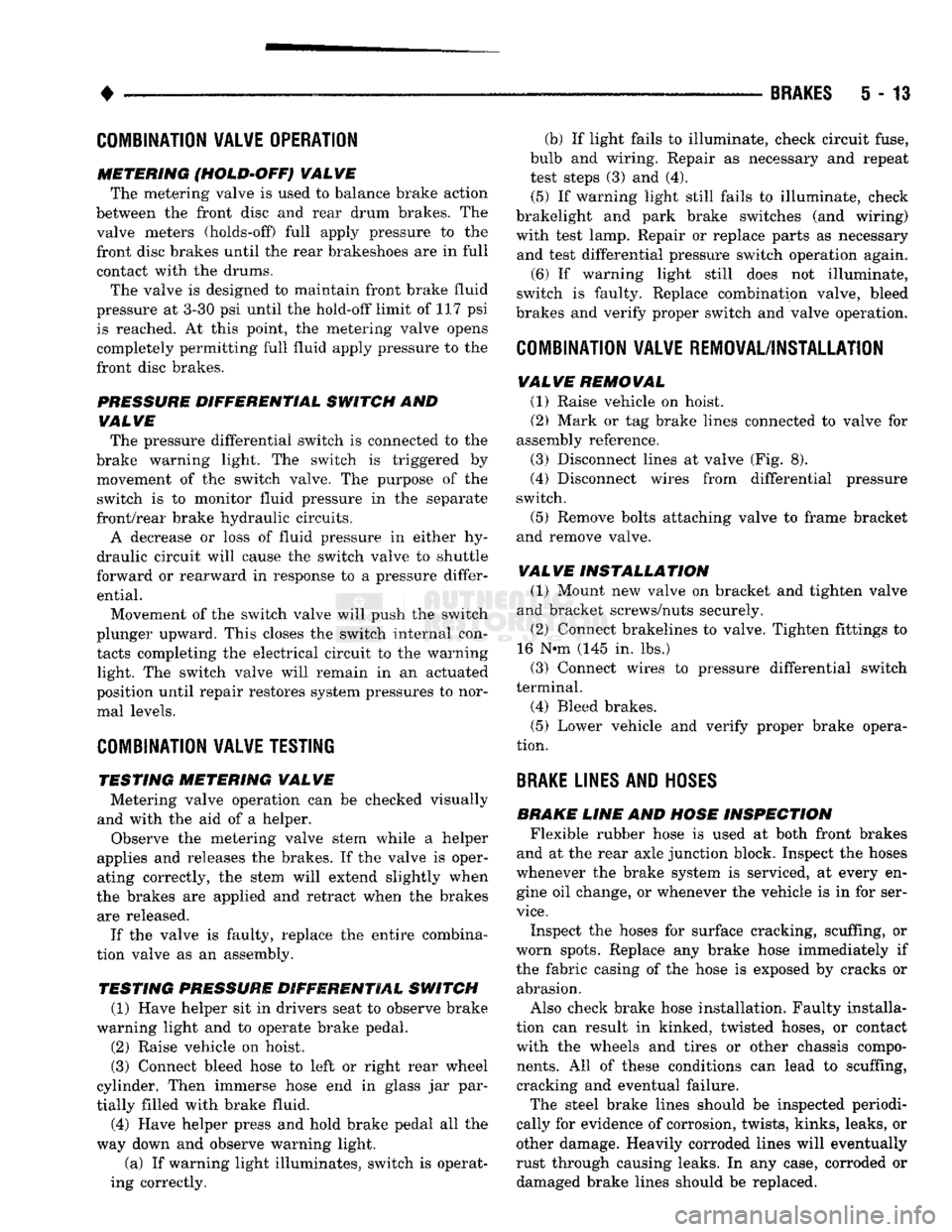
(3) Disconnect lines at valve (Fig. 8).
(4) Disconnect wires from differential pressure
switch.
(5) Remove bolts attaching valve to frame bracket
and remove valve.
VALVE INSTALLATION (1) Mount new valve on bracket and tighten valve
and bracket screws/nuts securely.
(2) Connect brakelines to valve. Tighten fittings to
16 N*m (145 in. lbs.)
(3) Connect wires to pressure differential switch
terminal. (4) Bleed brakes.
(5) Lower vehicle and verify proper brake opera
tion.
BRAKE
LINES AND
HOSES
BRAKE LINE AND HOSE INSPECTION Flexible rubber hose is used at both front brakes
and at the rear axle junction block. Inspect the hoses
whenever the brake system is serviced, at every en gine oil change, or whenever the vehicle is in for ser
vice.
Inspect the hoses for surface cracking, scuffing, or
worn spots. Replace any brake hose immediately if
the fabric casing of the hose is exposed by cracks or abrasion.
Also check brake hose installation. Faulty installa
tion can result in kinked, twisted hoses, or contact with the wheels and tires or other chassis compo
nents.
All of these conditions can lead to scuffing,
cracking and eventual failure.
The steel brake lines should be inspected periodi
cally for evidence of corrosion, twists, kinks, leaks, or
other damage. Heavily corroded lines will eventually
rust through causing leaks. In any case, corroded or damaged brake lines should be replaced.
Page 229 of 1502
5
- 42
BRAKES
•
CALIPER
DISASSEMBLY.
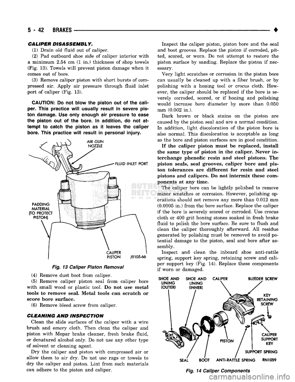
(1) Drain old fluid out of caliper.
(2) Pad outboard shoe side of caliper interior with
a minimum 2.54 cm (1 in.) thickness of shop towels
(Fig. 13). Towels will prevent piston damage when it
comes out of bore.
(3) Remove caliper piston with short bursts of com
pressed air. Apply air pressure through fluid inlet
port of caliper (Fig. 13).
CAUTION:
Do not
blow
the
piston
out of the
cali
per.
This
practice
will
usually
result
in
severe
pis
ton
damage.
Use only
enough
air
pressure
to
ease
the
piston
out of the
bore.
In
addition,
do not at
tempt
to catch the
piston
as it
leaves
the
caliper
bore.
This
practice
will
result
in
personal
injury.
PISTON
J9105-66
Fig.
13 Caliper
Piston
Removal (4) Remove dust boot from caliper.
(5) Remove caliper piston seal from caliper bore
with small wood or plastic tool. Do not use metal tools to remove seal. Metal tools can scratch or score bore surface. (6) Remove bleed screw from caliper.
CLEANING
AND INSPECTION Clean the slide surfaces of the caliper with a wire
brush and emery cloth. Then clean the caliper and
piston with Mopar brake cleaner, fresh brake fluid, or denatured alcohol only. Do not use any other type
of solvent or cleaning agent.
Dry the caliper and piston with compressed air or
allow them to air dry. Do not use rags or towels to
dry the caliper and piston. Lint from such materials
can adhere to the piston and caliper. Inspect the caliper piston, piston bore and the seal
and boot grooves. Replace the piston if corroded, pit
ted, scored, or worn. Do not attempt to restore the
piston surface by sanding. Replace the piston if nec essary.
Very light scratches or corrosion in the piston bore
can usually be cleaned up with a fiber brush, or by
polishing with a honing tool or crocus cloth. How ever, the caliper should be replaced if the bore is se
verely corroded, scored, or if honing and polishing
would increase bore diameter by more than 0.050
mm (0.002 in.).
Dark brown or black stains on the piston are
caused by the piston seal and are a normal condition.
In addition, light discoloration of the piston bore is also normal. This discoloration is acceptable as long as the bore and piston surfaces are in good condition.
If the caliper piston must be replaced, install
the same type of piston in the caliper. Never in
terchange phenolic resin and steel pistons. The piston seals, seal grooves, caliper bore and pis
ton tolerances are different for resin and steel
pistons and calipers. Do not intermix these com ponents at any time.
The caliper bore can be lightly polished to remove
minor scratches or corrosion. However, polishing op
erations should not remove any more than 0.012 mm (0.0005 in.) from the bore surface. Replace the caliper
if the bore is severely scored or corroded. Use crocus
cloth or 400 grit honing stones soaked in fresh brake
fluid to polish the bore surface. Be sure to flush and
clean the caliper thoroughly afterward. All residue generated by polishing must be removed to avoid po
tential damage to the piston, seal and bore after as sembly. Inspect and clean the inboard shoe anti-rattle
spring, support key spring, retaining screw and cali
per support key (Fig. 14). Replace these components if worn or damaged.
SHOE
AND
SHOE
AND
CALIPER
BLEEDER
SCREW
SEAL
BOOT
ANTI-RATTLE
SPRING
RN1059
Fig.
14 Caliper
Components
Page 230 of 1502
•
BRAKES
5 - 43
CAMPER
ASSEMBLY
(1) Mount caliper in vise equipped with protective
jaws.
Do not overtighten vise. Excessive pressure could cause bore distortion and piston binding. (2) Lubricate new piston seal and piston bore with
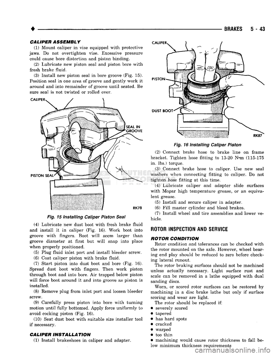
fresh brake fluid. (3) Install new piston seal in bore groove (Fig. 15).
Position seal in one area of groove and gently work it around and into remainder of groove until seated. Be
sure seal is not twisted or rolled over.
Fig.
15 Installing Caliper
Piston
Seal
(4) Lubricate new dust boot with fresh brake fluid
and install it in caliper (Fig. 16). Work boot into
groove with fingers. Boot will seem larger than
groove diameter at first but will snap into place
when properly positioned.
(5) Plug fluid inlet port and install bleeder screw. (6) Coat caliper piston with brake fluid.
(7) Start piston into dust boot and bore (Fig. 16).
Spread dust boot with fingers. Then work piston
through boot and into bore. Air trapped below piston
will force boot around it and into groove as piston is installed.
(8) Remove plug from inlet port and loosen bleeder
screw.
(9) Carefully press piston into bore with turning
motion until fully bottomed. Apply force uniformly to avoid cocking piston (Fig. 16).
(10) Seat dust boot with suitable size installer tool
if necessary.
CALIPER
INSTALLATION
(1) Install brakeshoes in caliper and adapter.
Fig.
16 Installing Caliper
Piston
(2) Connect brake hose to brake line on frame
bracket. Tighten hose fitting to 13-20 N«m (115-175 in. lbs.) torque.
(3) Connect brake hose to caliper. Use new seal
washers when connecting fitting to caliper. Do not
tighten hose fitting at this time.
(4) Lubricate caliper and adapter slide surfaces
with Mopar high temperature grease, or an equiva lent grease.
(5) Install and secure caliper in adapter.
(6) Fill master cylinder and bleed brakes.
(7) Install wheel and tire assemblies and lower ve
hicle.
ROTOR INSPECTION AND
SERVICE
ROTOR
CONDITION
Rotor condition and tolerances can be checked with
the rotor mounted on the axle. However, wheel bear ing end play should be reduced to zero before check
ing lateral runout.
The rotor braking surfaces should not be machined
unless actually necessary. Light surface rust and scale can be removed in a lathe equipped with dual
sanding discs.
Worn, or scored rotor surfaces can be restored by
machining in a disc brake lathe but only if surface scoring and wear are light.
The rotor should be replaced if:
• severely scored
• tapered
• has hard spots
• cracked
• warped
• too thin
• machining would cause rotor thickness to fall be
low minimum thickness requirements
Page 234 of 1502
BRAKES
5 - 47
(8) Disengage and remove adjuster screw assembly
from brakeshoes.
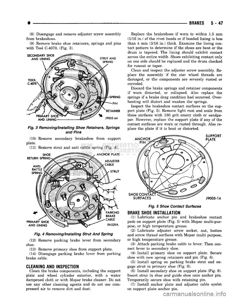
(9) Remove brake shoe retainers, springs and pins
with Tool C-4070, (Fig. 3). Fig. 3 Removing/Installing Shoe Retainers, Springs
and Pins (10) Remove secondary brakeshoe from support
plate. (11) Remove strut and anti rattle spring (Fig. 4).
Fig. 4 Removing/Installing Strut And Spring
(12) Remove parking brake lever from secondary
shoe.
(13) Remove primary shoe from support plate.
(14) Disengage parking brake lever from parking
brake cable.
CLEANING AND INSPECTION
Clean the brake components, including the support
plate and wheel cylinder exterior, with a water dampened cloth or with Mopar brake cleaner. Do not
use any other cleaning agents and do not use com
pressed air to remove dirt and dust. Replace the brakeshoes if worn to within 1.5 mm
(1/16 in.) of the rivet heads or if bonded lining is less
than 4 mm (3/16 in.) thick. Examine the lining con
tact pattern to determine if the shoes are bent or the drum is tapered. The lining should exhibit contact across the entire width. Shoes exhibiting contact only
on one side should be replaced and the drum checked
for runout or taper.
Clean and inspect the adjuster screw assembly. Re
place the assembly if the star wheel threads are damaged, or the components are severely rusted or corroded.
Discard the brake springs and retainer components
if worn distorted, or collapsed. Also replace the springs if a brake drag condition had occurred. Over
heating will distort and weaken the springs. Inspect the brakeshoe contact surfaces on the sup
port plate (Fig. 5). Remove light rust and scale from
these surfaces with 180 grit emery cloth or sandpa
per. However, replace the support plate if any of the contact surfaces are worn or rusted through. Also re
place the plate if it is bent or distorted.
Fig. 5 Shoe Contact Surfaces
BRAKE
SHOE INSTALLATION
(1) Lubricate anchor pin and brakeshoe contact
pads on support plate (Fig. 5) with Mopar multi-pur
pose,
or high temperature grease. (2) Lubricate adjuster screw socket, nut, button
and screw thread surfaces with Mopar multi purpose,
or high temperature grease. (3) Attach parking brake cable to lever. Then con
nect lever to secondary shoe. (4) Install primary shoe on support plate. Secure
shoe with new spring retainers and pin (Fig. 6). (5) Install spring on parking brake strut and en
gage strut in primary shoe (Fig. 6). (6) Install secondary shoe on support plate (Fig. 6).
Insert strut in shoe and guide shoe onto anchor pin.
Temporarily secure shoe with retaining pin. (7) Install anchor plate and adjuster cable eyelet
on support plate anchor pin.