Page 858 of 1640

G551 '93-'96 Models )
G551 '93-'96 Models)
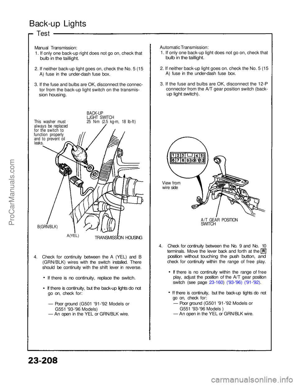
Back-up Lights
Test
Manual Transmission:
1
.
If only one back-up right does not go on, check that
bul
b
in the taillight.
2
.
If neither back-up light goes on, check the No. 5 (15
A) fuse in the under-dash fuse box.
3
.
If the fuse and bulbs are OK, disconnect the connec- to
r
from the back-up light switch on the transmis-
sio
n
housing.
BACK-UP
LJGHT SWITCH
25 N·m (2.5 kg-m, 18 Ib-ft)
This washer must
always be replaced
for the switch to
function properly and to prevent oil
leaks.
B(GRN/BLK)
A(YEL)
TRANSMISSION HOUSING
4. Check for continuity between the A (YEL) and B (GRN/BLK) wires with the switch installed. There
should be continuity with the shift lever in reverse.
If there is no continuity, replace the switch.
If there is continuity, but the back-up lights do not
go on, check for:
— Poor ground (G501 '91-'92 Models or
— An open in the YEL or GRN/BLK wire. 4. Check for continuity between the No. 9 and No. 10 terminals. Move the lever back and forth at the
position without touching the push button, and
check for continuity within the range of free play.
If there is no continuity within the range of freeplay, adjust the position of the A/T gear position
switch (see page 23-160) ('93-'96) ('91-'92).
ff there is continuity, but the back-up tights do not go on, check for:
— Poor ground (G501 '91-'92 Models or
— An open in the YEL or GRN/BLK wire.
A/T GEAR POSITION
SWITCH
View from
wire side
Automatic Transmission:
1
.
If only one back-up light does not go on, check that
bul
b
in the taillight.
2
.
If neither back-up light goes on. check the No. 5 (15
A) fuse in the under-dash fuse box.
3
.
If the fuse and bulbs are OK, disconnect the 12-P
connector from the A/T gear position switch (back-
u
p
light switch).
ProCarManuals.com
Page 860 of 1640

(G551) '95-'96 Models.
(G401,G402,G551) '93-94 Models or
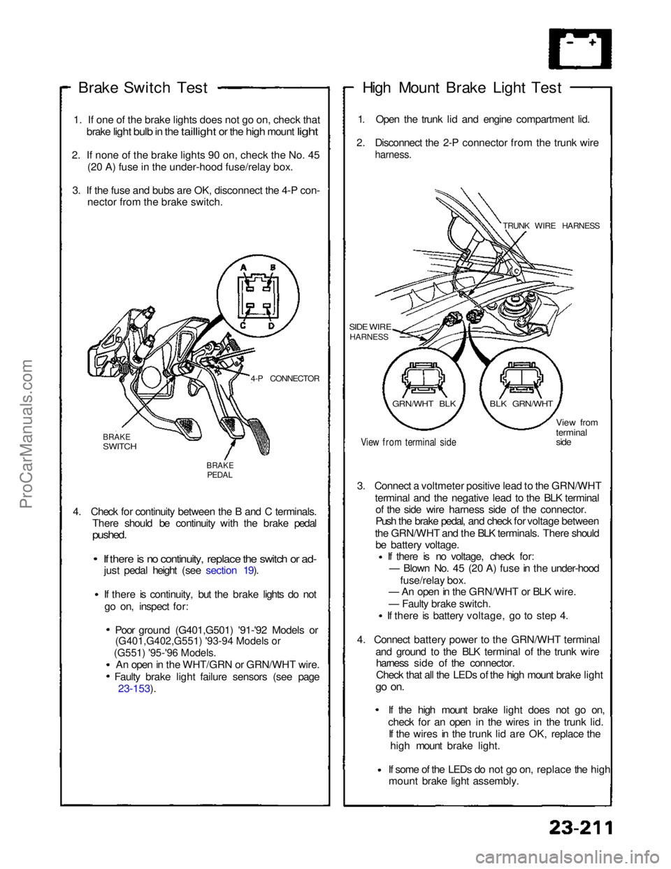
Brake Switch
Test
1
.
If one of the brake lights does not go on, check that
brake
light bulb in the taillight or the high mount light
2
.
If none of the brake lights 90 on, check the No. 45 (2
0
A) fuse in the under-hood fuse/relay box.
3
.
If the fuse and bubs are OK, disconnect the 4-P con- necto
r
from the brake switch.
4-P CONNECTOR
BRAKE
SWITCH
BRAKE
PEDAL
4. Check for continuity between the B and C terminals. There should be continuity with the brake pedal
pushed.
If there is no continuity, replace the switch or ad-
just pedal height (see section 19).
If there is continuity, but the brake lights do not
go on, inspect for:
Poor ground (G401,G501) '91-'92 Models or
An open in the WHT/GRN or GRN/WHT wire. Faulty brake light failure sensors (see page 23-153). High Mount Brake Light Test
1. Open the trunk lid and engine compartment lid.
2. Disconnect the 2-P connector from the trunk wire
harness.
TRUNK WIRE HARNESS
SIDE WIRE
HARNESS
View from terminal side
View from
terminal
side
3. Connect a voltmeter positive lead to the GRN/WHT terminal and the negative lead to the BLK terminalof the side wire harness side of the connector.
Push the brake pedal, and check for voltage between
the GRN/WHT and the BLK terminals. There should be battery voltage. If there is no voltage, check for:
— Blown No. 45 (20 A) fuse in the under-hood
fuse/relay box.
— An open in the GRN/WHT or BLK wire.
— Faulty brake switch.
If there is battery voltage, go to step 4.
4. Connect battery power to the GRN/WHT terminal and ground to the BLK terminal of the trunk wireharness side of the connector.
Check that all the LEDs of the high mount brake light
go on.
If the high mount brake light does not go on,check for an open in the wires
in the trunk lid.
If the wires in the trunk lid are OK, replace the
high mount brake light.
If some of the LEDs do not go on,
replace the high
mount brake light assembly.
GRN/WHT BLK
BLK GRN/WHTProCarManuals.com
Page 862 of 1640
Side Marker/Turn Signal/Hazard Flasher System
Component Location Index
SRS components are located in this area. Review the SRS component locations, precautions, and procedures in the SRS
section (24) before performing repairs or service.
TURN SIGNAL INDICATOR LIGHTS(In the gauge assembly)
Gauge Assembly, page 23-125 HAZARD WARNING SWITCH
Removal, page 23-220
Test, page 23-221
HEADLIGHT SWITCH
Test, page 23-181
Replacement, page 23-182
TURN SIGNAL/HAZARD RELAY
Input Test, page 23-218
UNDER-DASH FUSE BOX TURN SIGNAL SWITCH
Test, page 23-181
Replacement, page 23-182 TURN SIGNAL CANCEL UNIT
Input Test, page 23-219
SIDE MARKER FLASHER CIRCUIT
(In the integrated control unit)
Input Test, page 23-168 ('94-'96) ('91-'93)ProCarManuals.com
Page 874 of 1640
Entry Light Timer System
Component Location Index
SRS components are located in this area. Review the SRS
component locations, precautions, and procedures in the
SRS section (24) before performing repairs or service.
Description: It the driver's door has been opened by the
outer handle, the foot well light and a light at the Ignition
switch go on and stay on for about eight seconds after
the driver's door has been dosed.
IGNITION KEY LIGHT
Replacement, page 23-229
FOOT WELL LIGHT
Replacement, page 23-229
DRIVER'S DOOR SWITCH
(Built into the door lock actuator assembly)
Test, page 23-204
UNDER-DASH FUSE BOX ENTRY LIGHT TIMER CIRCUIT
( Built into the integrated control unit)
Input Test, page 23-161 ('93-'96) ('91-'92)
ProCarManuals.com
Page 888 of 1640
Horns
Component Location Index
SRS components are located in this area. Review the
SRS component locations, precautions, and procedures
in the SRS section (24) before performing repairs or ser-
vice.
HORN RELAY
Test, page 23-249
UNDER-HOOD RELAY
BOX A
CABLE REEL
Test, page 23-250
HORN SWITCH
Test, page 23-249
Overhaul, section 17
SECURITY HORNTest, page 23-248
LEFT HORN
Test, page 23-248
RIGHT HORN
Test, page 23-248
SECURITY CONTROL
UNIT
Inpu
t
Test, page 23-320
('94-'96) ('93) ('91-'92)
UNDER-HOOD
FUSE/RELAY BOX
Description
Security Alarm System:
The security alarm system is an anti-theft alarm system. If someone tries to open the trunk, hood or either door without
the ignition key, or if the roof is not fully latched the security control unit senses a signal from the sensors and activates
relays to flash the headlights and sound the horn for about two minutes.ProCarManuals.com
Page 897 of 1640

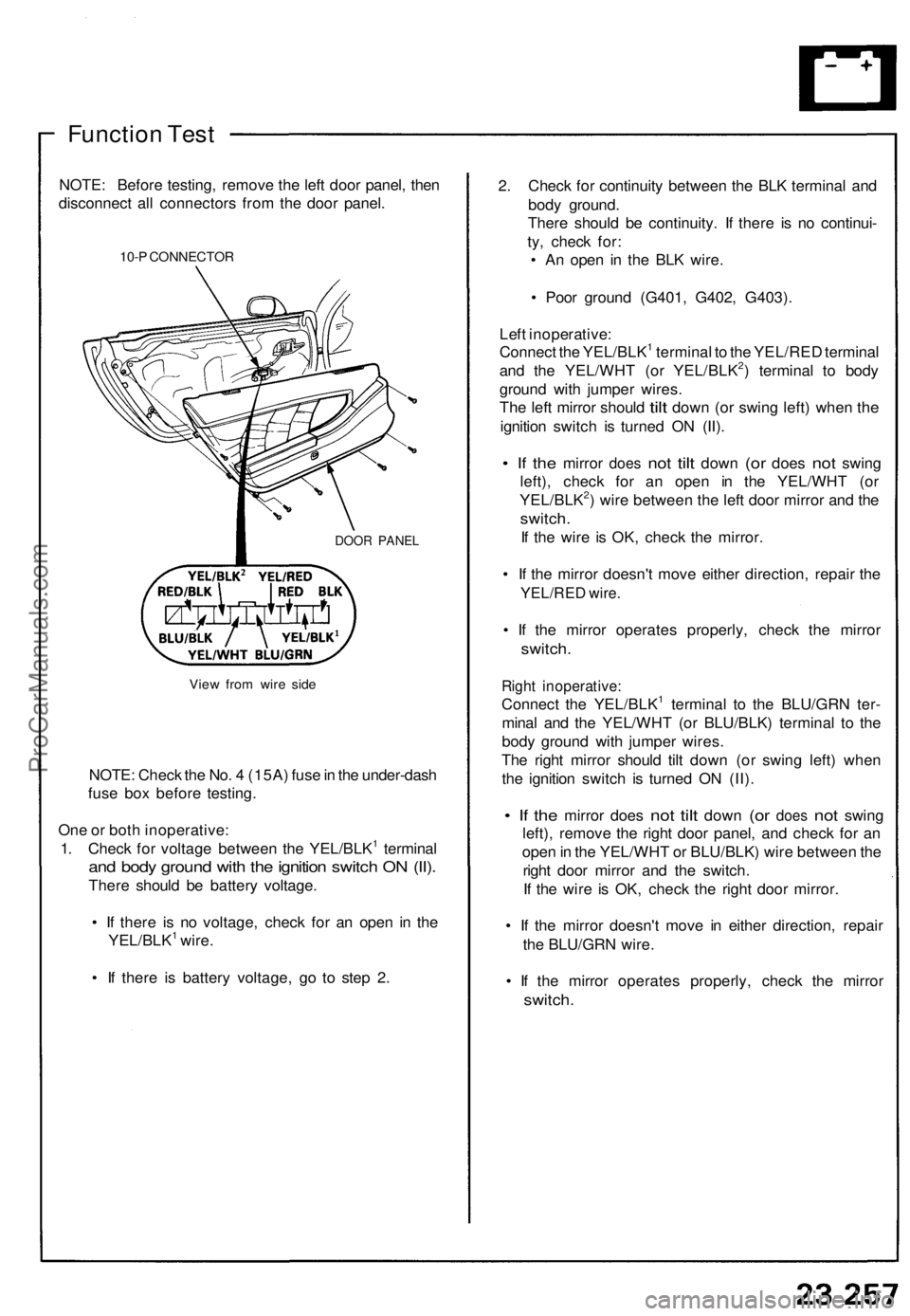
Function Test
NOTE: Before testing, remove the left door panel, then
disconnect all connectors from the door panel.
10-P CONNECTOR
DOOR PANEL
View from wire side
NOTE: Check the No. 4 (15A) fuse in the under-dash
fuse box before testing.
One or both inoperative:
1. Check for voltage between the YEL/BLK1 terminal
and body ground with the ignition switch ON (II).
There should be battery voltage.
• If there is no voltage, check for an open in the
YEL/BLK1 wire.
• If there is battery voltage, go to step 2.
2. Check for continuity between the BLK terminal and
body ground.
There should be continuity. If there is no continui-
ty, check for:
• An open in the BLK wire.
• Poor ground (G401, G402, G403).
Left inoperative:
Connect the YEL/BLK1 terminal to the YEL/RED terminal
and the YEL/WHT (or YEL/BLK2) terminal to body
ground with jumper wires.
The
left mirror should
tilt
down
(or
swing left) when
the
ignition switch is turned ON (II).
• If the
mirror
does
not
tilt
down
(or
does
not
swing
left), check for an open in the YEL/WHT (or
YEL/BLK2) wire between the left door mirror and the
switch.
If the wire is OK, check the mirror.
• If the mirror doesn't move either direction, repair the
YEL/RED wire.
• If the mirror operates properly, check the mirror
switch.
Right inoperative:
Connect the YEL/BLK1 terminal to the BLU/GRN ter-
minal and the YEL/WHT (or BLU/BLK) terminal to the
body ground with jumper wires.
The right mirror should tilt down (or swing left) when
the ignition switch is turned ON (II).
• If the
mirror does
not
tilt
down
(or
does
not
swing
left), remove the right door panel, and check for an
open in the YEL/WHT or BLU/BLK) wire between the
right door mirror and the switch.
If the wire is OK, check the right door mirror.
• If the mirror doesn't move in either direction, repair
the BLU/GRN wire.
• If the mirror operates properly, check the mirror
switch.ProCarManuals.com
Page 908 of 1640

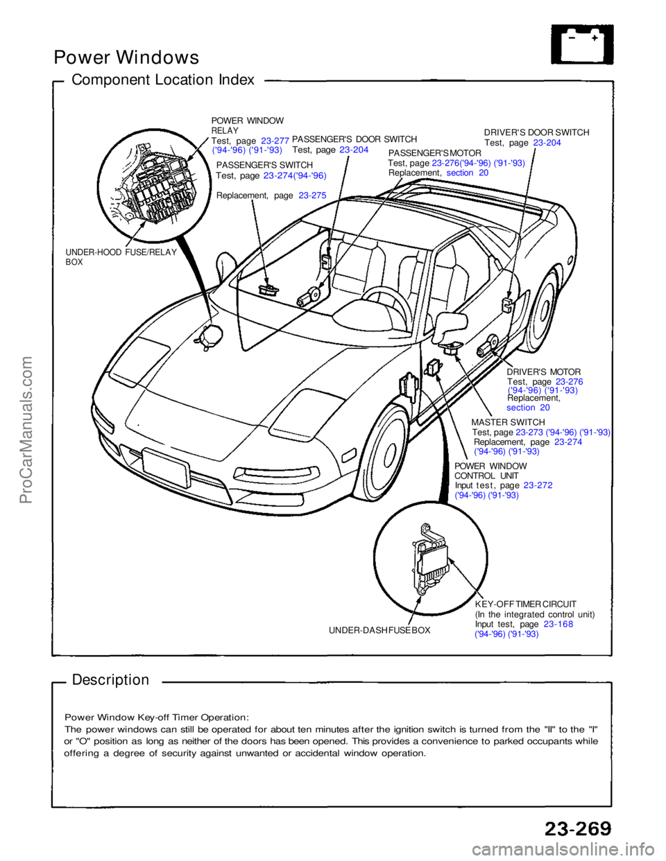
Power Windows
Component Location Index
POWER WINDOW
RELAY
Test
,
page 23-277
('94-'96) ('91-'93)
PASSENGER'S SWITCH
Test, page 23-274('94-'96)
Replacement, page
23-275
PASSENGER'S DOOR SWITCH
Test, page 23-204
PASSENGER'S MOTOR
Test, page 23-276('94-'96) ('91-'93)
Replacement, section 20
DRIVER'S DOOR SWITCH
Test, page 23-204
DRIVER'S MOTORTest, page 23-276('94-'96) ('91-'93)
Replacement,
section 20
MASTER SWITCH
Test, page 23-273 ('94-'96) ('91-'93)
Replacement, page 23-274
('94-'96) ('91-'93)
POWER WINDOW
CONTROL UNIT
Input test, page 23-272
('94-'96) ('91-'93)
KEY-OFF TIMER CIRCUIT
(In the integrated control unit)
Input test, page 23-168
('94-'96) ('91-'93)
UNDER-DASH FUSE BOX
UNDER-HOOD FUSE/RELAY
BOX
Description
Power Window Key-off Timer Operation:
The power windows can still be operated for about ten minutes after the ignition switch is turned from the "II" to the "I"
or "O" position as long as neither of the doors has been opened. This provides a convenience to parked occupants while
offering a degree of security against unwanted or accidental window operation.ProCarManuals.com
Page 915 of 1640
Relay Test
1. Remove the power window relay in the under-hood
fuse/relay box.
2. Check continuity at the relay terminals.
• There should be continuity between the C and D
terminals.
• There should be continuity between the A and B
terminals when power and ground are connect-
ed to the C and D terminals.
• There should be no continuity between the A and
B terminals when power is disconnected.ProCarManuals.com