Page 1121 of 1640
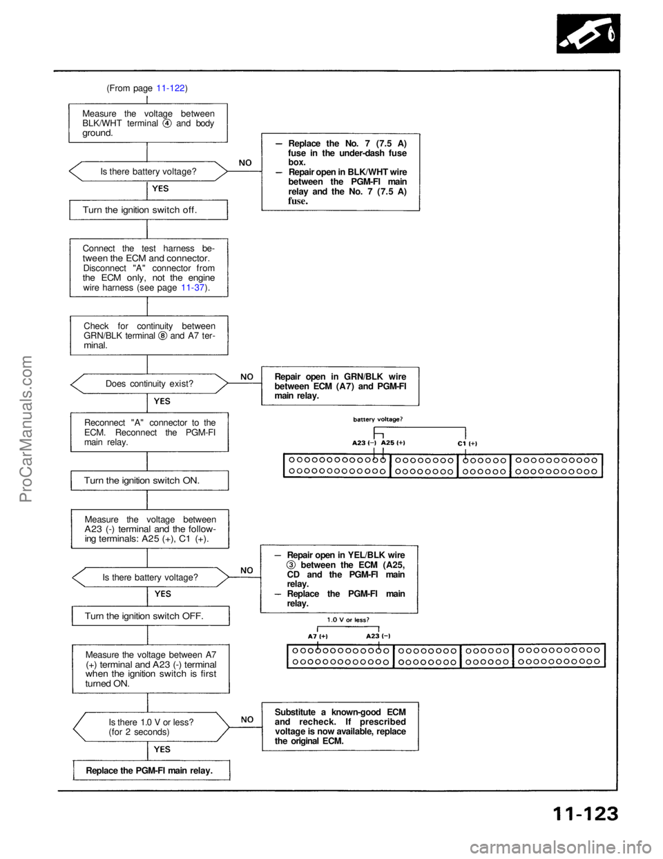
(From page 11-122)
Connect the test harness be-
tween the ECM and connector.
Disconnect "A" connector from
the ECM only, not the engine
wire harness (see page 11-37).
Measure the voltage between BLK/WHT terminal and body
ground.
Is there battery voltage?
Check for continuity between GRN/BLK terminal and A7 ter-
minal.
Does continuity exist?
Reconnect "A" connector to the
ECM. Reconnect the PGM-FI
main relay.
Turn the ignition switch ON.
Measure the voltage between
A23 (-) terminal and the follow-
ing terminals: A25 (+), C1 (+).
Is there battery voltage?
Turn the ignition switch OFF.
Measure the voltage between A7
(+) terminal and A23 (-) terminal
when the ignition switch is first
turned ON.
Is there 1.0 V or less?
(for 2 seconds)
Replace the PGM-FI main relay. Replace the No. 7 (7.5 A)
fuse in the under-dash fuse
box.
Repair open in BLK/WHT wire
between the PGM-FI main
relay and the No. 7 (7.5 A)
fuse.
Repair open in GRN/BLK wire
between ECM (A7) and PGM-FI
main relay. Repair open in YEL/BLK wire between the ECM (A25,
CD and the PGM-FI main
relay.
Replace the PGM-FI main
relay.
Substitute a known-good ECM
and recheck. If prescribed voltage is now available, replace
the original ECM.
Turn the ignition switch off.ProCarManuals.com
Page 1208 of 1640
Troubleshooting Procedures
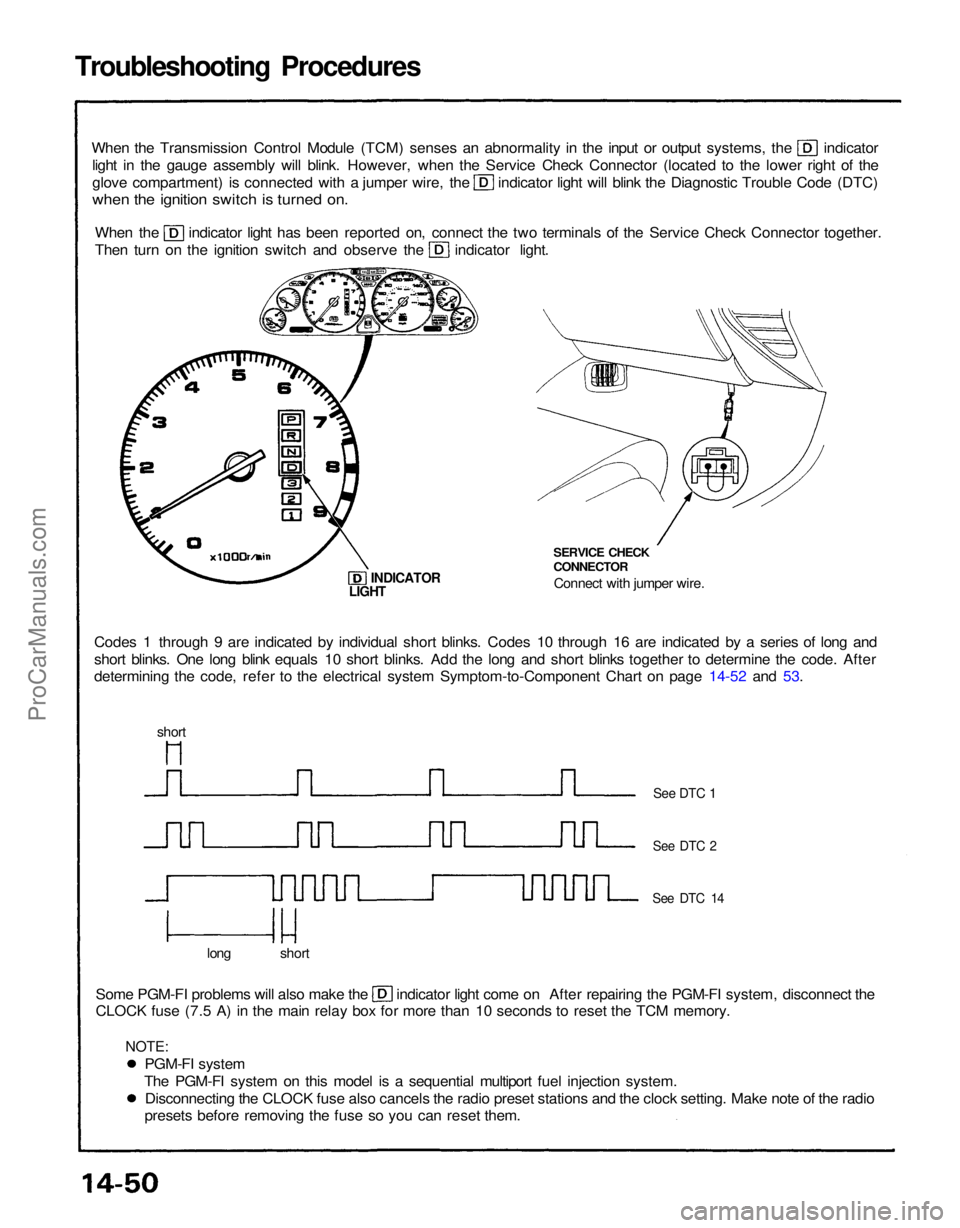
When the Transmission Control Module (TCM) senses an abnormality in the input or output systems, the indicator
light in the gauge assembly will blink. However, when the Service Check Connector (located to the lower right of the glove compartment) is connected with a jumper wire, the indicator light will blink the Diagnostic Trouble Code (DTC)
when the ignition switch is turned on.
When the indicator light has been reported on, connect the two terminals of the Service Check Connector together.
Then turn on the ignition switch and observe the indicator light.
Codes 1 through 9 are indicated by individual short blinks. Codes 10 through 16 are indicated by a series of long and
short blinks. One long blink equals 10 short blinks. Add the long and short blinks together to determine the code. After
determining the code, refer to the electrical system Symptom-to-Component Chart on page 14-52 and 53. SERVICE CHECK
CONNECTOR
Connect with jumper wire.
INDICATOR
Some PGM-FI problems will also make the indicator light come on After repairing the PGM-FI system, disconnect the
CLOCK fuse (7.5 A) in the main relay box for more than 10 seconds to reset the TCM memory.
long short
See DTC 1
See DTC 2
See DTC 14
LIGHT
short
PGM-FI system
The PGM-FI system on this model is a sequential multiport fuel injection system. Disconnecting the CLOCK fuse also cancels the radio preset stations and the clock setting. Make note of the radio
presets before removing the fuse so you can reset them.
NOTE:ProCarManuals.com
Page 1209 of 1640
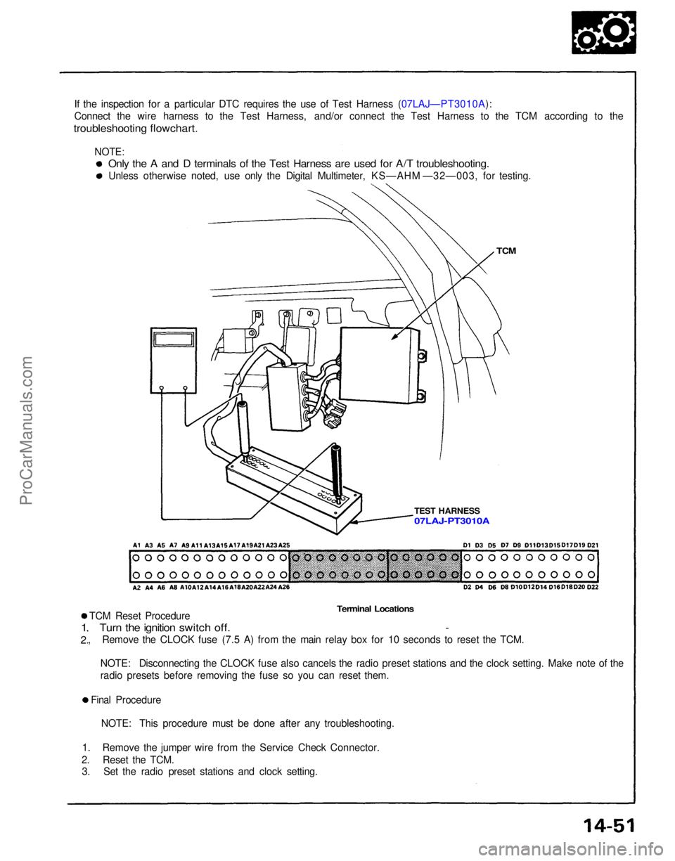
If the inspection for a particular DTC requires the use of Test Harness (07LAJ—PT3010A):
Connect the wire harness to the Test Harness, and/or connect the Test Harness to the TCM according to the
troubleshooting flowchart.
TCM
TEST HARNESS
Terminal Locations
TCM Reset Procedure
Turn the ignition switch off. -
, Remove the CLOCK fuse (7.5 A) from the main relay box for 10 seconds to reset the TCM.
1
2
NOTE: Disconnecting the CLOCK fuse also cancels the radio preset stations and the clock setting. Make note of the
radio presets before removing the fuse so you can reset them.
Final Procedure NOTE: This procedure must be done after any troubleshooting.
1. Remove the jumper wire from the Service Check Connector.
2. Reset the TCM. 3. Set the radio preset stations and clock setting.
Only the A and D terminals of the Test Harness are used for A/T troubleshooting.
Unless otherwise noted, use only the Digital Multimeter, KS—AHM —32—003, for testing.
07LAJ-PT3010A
NOTE:ProCarManuals.com
Page 1211 of 1640
If a customer describes the symptoms for codes 3, 6, 11, 14 or 1 5 yet the indicator light is not blinking, it will
be necessary to recreate the symptom by test driving, and then checking the indicator light with the ignition
still
ON.
If the indicator light displays codes 1,2,3,8, 11, or 16, check first the No. 9, 13 and 18 and fuse before elec-
trical troubleshooting.
If any of the fuses have blown, repair them and then recheck. If the indicator light displays codes other than those listed above or stays lit continuously, the TCM is faulty.
Sometimes the indicator light and the Malfunction Indicator Lamp (MID/Check Engine light may come on
simultaneously. If so, check the PGM-FI system according to the number of blinks on the MIL/Check Engine light,
then reset the memory by removing the CLOCK fuse in the main relay box for more than 10 seconds. Drive the vehicle for several minutes at speed over 30 mph (50 km/h), then recheck the MIL/Check Engine light.PGM-FI system
The PGM-FI system on this model is a sequential multiport fuel injectin system.
The indicator light may comes on, indicating a system problem, when, in fact, there is a poor or intermittent
electrical connection. First, check the electrical connections, clean or repair connections if necessary.If the electrical readings are not as specified when using the test harness, check the test harness connections
before proceeding.
Disconnecting the CLOCK fuse also cancels the radio preset stations and the clock setting. Make note of the radio
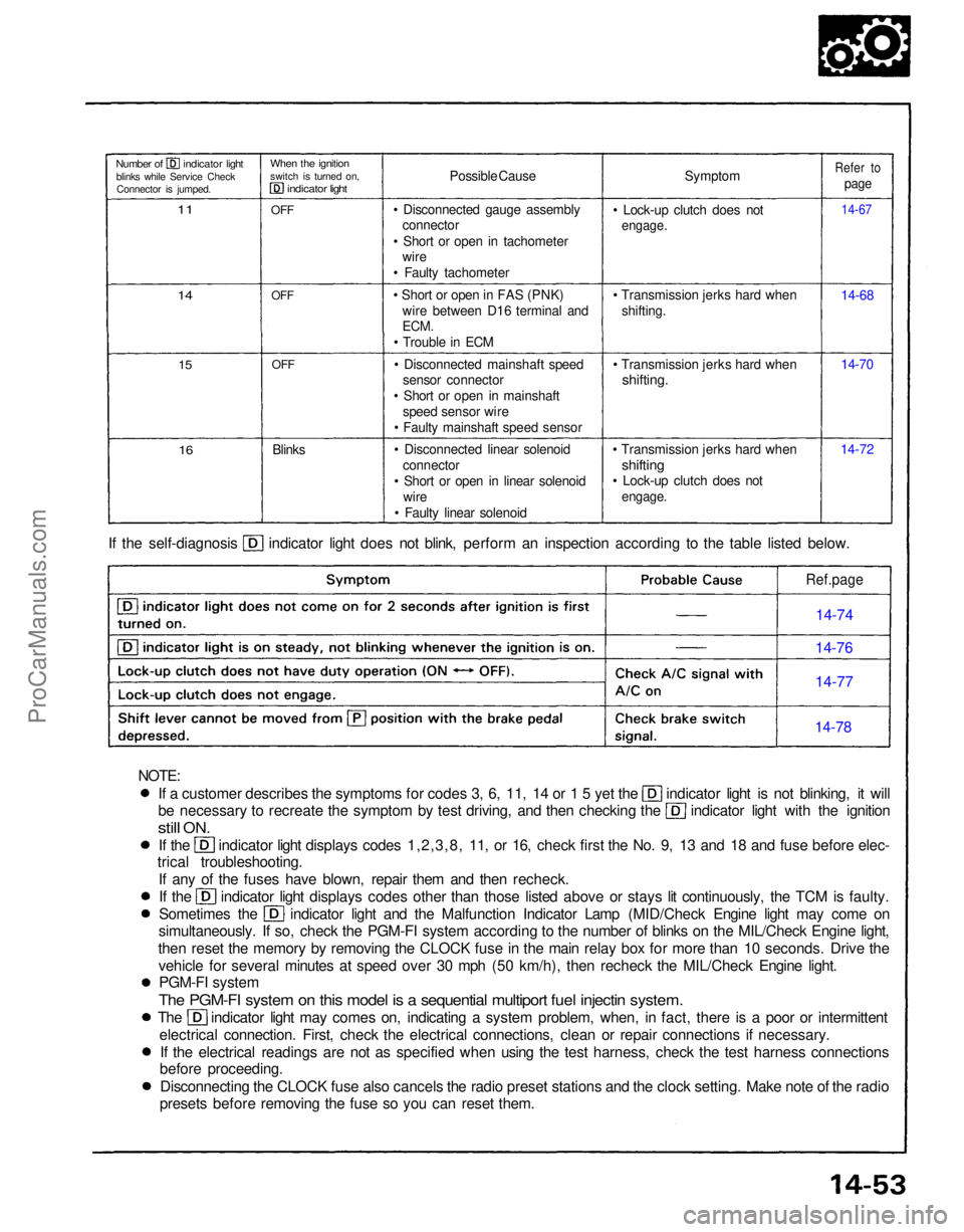
presets before removing the fuse so you can reset them. If the self-diagnosis indicator light does not blink, perform an inspection according to the table listed below.
Symptom
• Lock-up clutch does not
engage.
• Transmission jerks hard when shifting.
• Transmission jerks hard when
shifting.
• Transmission jerks hard when
shifting
• Lock-up clutch does not
engage.
14-7214-70 14-68
14-67
Refer to
page
Possible Cause
• Disconnected gauge assembly connector
• Short or open in tachometer wire
• Faulty tachometer
• Short or open in FAS (PNK) wire between D16 terminal and
ECM.
• Trouble in ECM
• Disconnected mainshaft speed sensor connector
• Short or open in mainshaft speed sensor wire
• Faulty mainshaft speed sensor
• Disconnected linear solenoid connector
• Short or open in linear solenoid wire
• Faulty linear solenoid
Blinks
OFF
OFF
OFF
When the ignition
switch is turned on,
indicator light
Number of indicator light
blinks while Service CheckConnector is jumped.
11
14
15
16
Ref.page
14-74
14-76
14-77
14-78
NOTE:ProCarManuals.com
Page 1325 of 1640
FUSE BOX
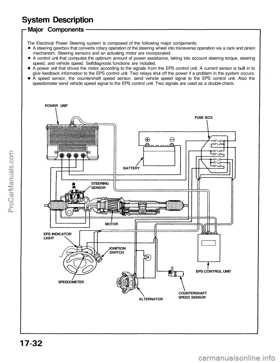
System Description
Major Components
The Electrical Power Steering system is composed of the following major components:
EPS CONTROL UNIT
COUNTERSHAFT
SPEED SENSOR
ALTERNATOR
SPEEDOMETER
EPS INDICATOR
LIGHT
STEERING
SENSOR
BATTERY
POWER UNIT
MOTOR
IGNITION
SWITCH
A steering gearbox that converts rotary operation of the steering wheel into transverse operation via a rack and pinion
mechanism. Steering sensors and an actuating motor are incorporated.
A control unit that computes the optimum amount of power assistance, taking into account steering torque, steering
speed, and vehicle speed. Selfdiagnosis functions are included.
A power unit that drives the motor according to the signals from the EPS control unit. A current sensor is built in to
give feedback information to the EPS control unit. Two relays shut off the power if a problem in the system occurs.
A speed sensor, the countershaft speed sensor, send vehicle speed signal to the EPS control unit. Also the
speedometer send vehicle speed signal to the EPS control unit. Two signals are used as a double-check.ProCarManuals.com
Page 1333 of 1640
Wiring Locations
EPS CONTROL UNIT
MAIN RELAY BOX
POWER UNIT
TORQUE SENSOR 6-P CONNECTOR/
STEERING WHEEL SPEED SENSOR
4-P CONNECTOR
STEERING GEARBOX
(TORQUE SENSOR/STEERING WHEEL
SPEED SENSOR)
UNDER-DASH FUSE/RELAY BOX
TRANSMISSION CONTROL MODULE (TCM)
22-P CONNECTOR
VEHICLE SPEED SENSOR
(VSS)
ALTERNATOR 4-P CONNECTOR
EPS INDICATOR LIGHTProCarManuals.com
Page 1336 of 1640
Troubleshooting
Diagnostic Trouble Code (DTC) Display
When the service check connector terminals are connected with a jumper wire, the EPS control unit blinks the EPS indi-
cator light to indicate the DTC. The DTC is indicated by a series of long and short blinks. One long blink equals 10 shortblinks. Add the long and short blinks together to determine the DTC, then refer to the Troubleshooting Chart on page 17-51.
Example 1.3 seconds
0.28 seconds
1.3 seconds
0.36 seconds
The control unit can memorize any number of simultaneous problems. The DTC is repeated sequentially beginning with
the lowest number.
The DTC is stored in the control unit memory even when the ignition switch is turned off. After repairing the EPS system,
disconnect the CLOCK fuse in the relay box for more than 10 seconds to reset the EPS control unit memory.ProCarManuals.com
Page 1361 of 1640
Component Location Index
INDICATOR LIGHT
ACTIVATION LIGHT INDICATOR LIGHT
UNDER-HOOD
FUSE/RELAY BOX
ABS
CONTROL UNIT
STEERING
ANGLE SENSOR
(page 19-138)
TCS SWITCH(page 19-137)
UNDER-DASH FUSE BOX
A/T GEAR POSITION
SWITCH
FAIL-SAFE RELAY
(page 19-137)
ENGINE
COMPARTMENT
FUSE/RELAY BOX
TRANSMISSON
CONTROL
MODULE (TCM)
ENGINE
GROUND
TCS CONTROL
UNIT
ENGINE CONTROL
MODULE (ECM)
ACCELERATOR
PEDAL
ANGLE
SENSOR
THROTTLE
ACTUATOR
THROTTLE
POSITION (TP)
SENSORProCarManuals.com