Page 1409 of 1640
UNDER HOOD FUSE/RELAY BOX
DIMME
R
RELAY
Test, page 23-189
UNDER-HOOD RELAY BOX A
TAILLKSHT RELAY
Test, page 23-190
HEADLIGHT RELAY
Test, page 23-189
RIGHT HEADLIGHT
RETRACTOR RELAY
Test, page 23-190
RIGHT HEADLIGHT
RETRACTOR MOTOR
Test, page 23-188
Replacement, page
23-186
RIGHT DAYTIME RUNNING
LIGHT (Canada)
Replacement, page
23-194
HEADLIGHTS
Ajustment, page 23-192
Replacement, page 23-193
LEFT DAYTIME RUNNING LIGHT (Canada)
Replacement
,
page 23-194
LEFT HEADLIGHT
RETRACTOR MOTOR
Test, page 23-188
Replacement, page 23-186 LEFT HEADLIGHT
RETRACTOR RELAY
Test
,
page 23-190
LEFT HEADLIGHT
RETRACTOR CUT RELAY
Test, page 23-190
RIGHT HEADLIGHT
RETRACTOR CUT RELAY
Test, page 23-190ProCarManuals.com
Page 1423 of 1640
Power Door Locks
Component Location Index
UNDER-HOOD FUSE/BELAY BOX
Located at right side offront compartment
IGNITION KEY SWITCH
Test, page 23-167
DRIVER'S DOOR LOCK SWITCH
Test
,
page 23-260
DRIVER'S DOOR LOCK
ACTUATOR ASSEMBLY
Test
,
page 23-258Replacement
,
section 20
DRIVER'S DOOR SWITCH
Test, page 23-198
PASSENGERS'S DOOR LOCK
ACTUATOR ASSEMBLY
Test
,
page 23-259Replacement
,
section 20
PASSENGER'S DOOR SWITCH
Test
,
page 23-198
PASSENGER'S DOOR LOCK
SWITCH
Test
,
page 23-260
POWER DOOR LOCK
CONTROL UNIT
Inpu
t
Test,
ProCarManuals.com
Page 1428 of 1640

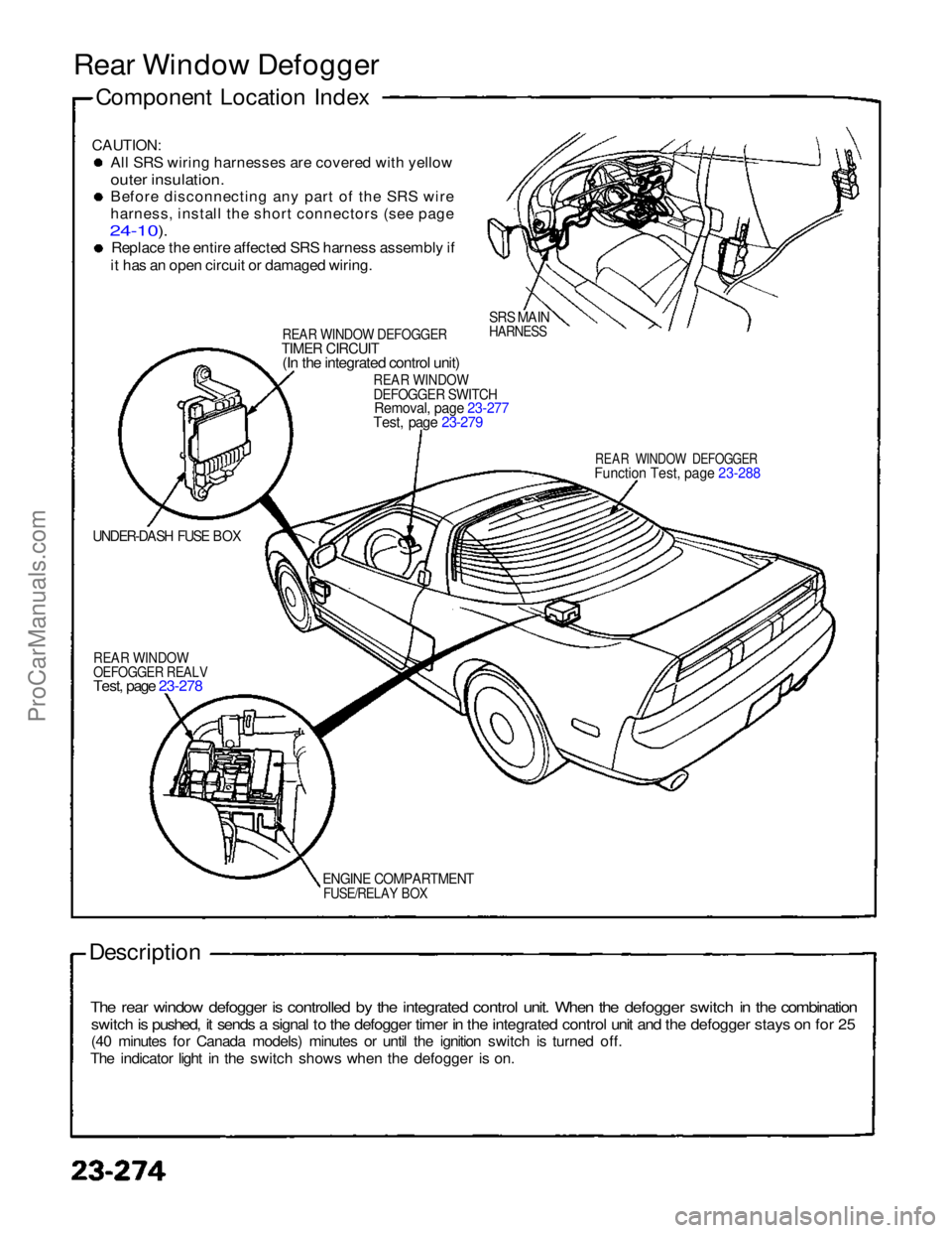
Rear Window Defogger
Component Location Index
CAUTION:
Al
l
SRS wiring harnesses are covered with yellow
outer insulation.
Befor
e
disconnecting any part of the SRS wire
harness
,
install the short connectors (see page
24-10).
Replac
e
the entire affected SRS harness assembly if
it
has an open circuit or damaged wiring.
REA
R
WINDOW DEFOGGERTIME
R
CIRCUIT(I
n
the integrated control unit)
SRS MAIN
HARNESS
REA
R
WINDOWDEFOGGE
R
SWITCHRemoval
,
page 23-277
Test, page 23-279
REAR WINDOW DEFOGGER
Functio
n
Test, page 23-288
UNDER-DASH FUSE BOX
REA
R
WINDOWOEFOGGE
R
REALV
Test, page 23-278
ENGIN
E
COMPARTMENT
FUSE/RELAY BOX
Description
The rear window defogger is controlled by the integrated control unit. When the defogger switch in the combination
switch is pushed, it sends a signal to the defogger timer in the integrated control unit and the defogger stays on for 25
(40 minutes for Canada models) minutes or until the ignition switch is turned off.
The indicator light in the switch shows when the defogger is on.ProCarManuals.com
Page 1431 of 1640
Rear Window Defogger
Switch Light Bulb Replacement
1. Remove the steering column lower and upper covers.
2. Remove the four screws from the combination
switch.
3. Remove the rear window defogger switch (see previous page).
4. Remove the rear window defogger switch bulbs.
BULBS (0.91 W)
REAR WINDOW
DEFOGGER SWITCH Relay Test
1. Remove the defogger relay in the engine compart- ment fuse/relay box.
2. There should be continuity between the C and D terminals.
3. There should be continuity between the A and B terminals when power and ground are connected to
the C and D terminals.
There should be no continuity when power isdisconnected.ProCarManuals.com
Page 1441 of 1640
Troubleshooting
NOTE:
The numbers in the table show the troubleshooting sequence.
Before troubleshooting.
Check the No. 5 (10 A) fuse in the under-dash fuse box, and the No. 29 (50 A) and No. 45 (20 A) fuses in the
under-hood fuse/relay box.
Check that the horns sound.
Check that the tachometer works properly.ProCarManuals.com
Page 1487 of 1640

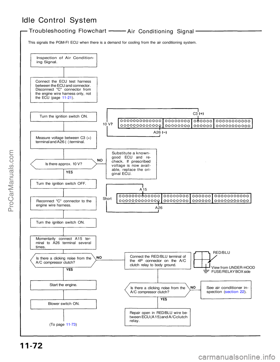
Idle Control System
Troubleshooting Flowchart
Air Conditioning Signal
This signals the PGM-FI ECU when there is a demand for cooling from the air conditioning system.
Inspection of Air Condition-
ing Signal.
Connect the ECU test harness
between the ECU and connector.
Disconnect "C" connector from
the engine wire harness only, not
the ECU (page 11-21).
Turn the ignition switch ON.
Measure voltage between C3 (+)
terminal and A26 (-) terminal.
Is there approx. 10 V?
Substitute a known-
good ECU and re-
check. If prescribed
voltage is now avail- able, replace the ori-
ginal ECU.
C3
A26
10 V
Turn the ignition switch OFF. Reconnect "C" connector to the
engine wire harness.
Turn the ignition switch ON.
Momentarily connect A15 ter-
minal to A26 terminal several
times.
Is there a clicking noise from the
A/C compressor clutch? Connect the RED/BLU terminal of
the 4P connector on the A/C
clutch relay to body ground. RED/BLU
A 15
Short
A26
View from UNDER-HOODFUSE/RELAY BOX side
Start the engine.
Is there a clicking noise from the
A/C compressor clutch?
See air conditioner in-
spection (section 22).
Repair open in RED/BLU wire be-
tween ECU (A15) and A/C clutch
relay.
Blower switch ON.
(To page 11-73)ProCarManuals.com
Page 1499 of 1640
6. Turn the ignition switch OFF.
7. Reconnect the 2P connector on the EACV, then
remove CLOCK fuse in the under-hood fuse/relay
box for 10 seconds to reset ECU.
8. Restart and idle the engine with no-load conditions
in which the headlights, blower fan, rear defogger,
cooling fan, and air conditioner are not operating
for one minute, then check the idle speed.
Idle speed should be:ProCarManuals.com
Page 1570 of 1640

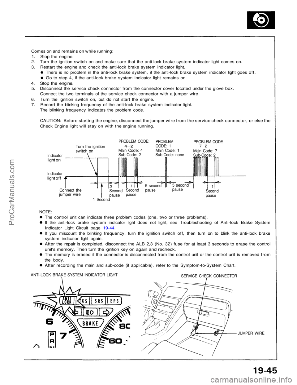
Comes on and remains on while running:
1. Stop the engine.
2. Turn the ignition switch on and make sure that the anti-lock brake system indicator light comes on.
3. Restart the engine and check the anti-lock brake system indicator light.
There is no problem in the anti-lock brake system, if the anti-lock brake system indicator light goes off. Go to step 4, if the anti-lock brake system indicator light remains on.
4. Stop the engine.
5. Disconnect the service check connector from the connector cover located under the glove box.
Connect the two terminals of the service check connector with a jumper wire.
6. Turn the ignition switch on, but do not start the engine. 7. Record the blinking frequency of the anti-lock brake system indicator light.
The blinking frequency indicates the problem code.
CAUTION: Before starting the engine, disconnect the jumper wire from the service check connector, or else the
Check Engine light will stay on with the engine running.
Turn the ignition
switch on
PROBLEM CODE:
4– 2
Main Code: 4
Sub-Code: 2
PROBLEM
CODE: 1
Main Code: 1
Sub-Code: none
PROBLEM CODE
7–2
Main Code: 7
Sub-Code: 2
Indicator
light on
Indicator
light off
Connect the
jumper wire
2
Second
pause
1
Second
pause
5 second
pause
5 second
pause
1
Second
pause
1 Second
NOTE:
The control unit can indicate three problem codes (one, two or three problems). If the anti-lock brake system indicator light does not light, see Troubleshooting of Anti-lock Brake System
Indicator Light Circuit page 19-44.
If you miscount the blinking frequency, turn the ignition switch off, then turn on to blink the anti-lock brake
system indicator light again. After the repair is completed, disconnect the ALB 2,3 (No. 32) fuse for at least 3 seconds to erase the control
unit's memory. Then turn the ignition key on again and recheck.
The memory is erased if the connector is disconnected from the control unit or the control unit is removed from
the body. After recording the main and sub-code (if applicable), refer to the Symptom-to-System Chart.
ANTI-LOCK BRAKE SYSTEM INDICATOR LIGHT
SERVICE CHECK CONNECTOR
JUMPER WIREProCarManuals.com