Page 1366 of 1640

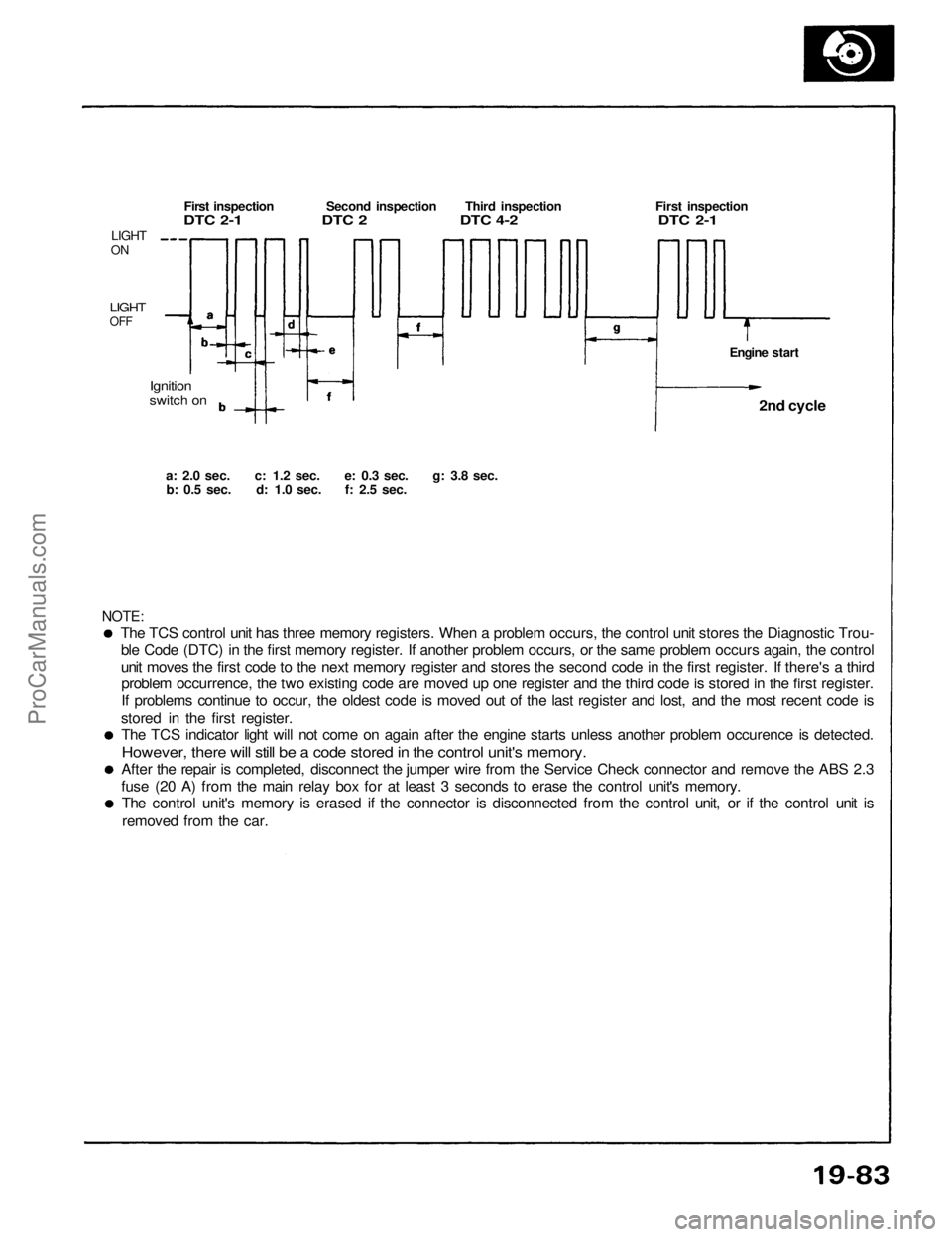
The TCS control unit has three memory registers. When a problem occurs, the control unit stores the Diagnostic Trou-
ble Code (DTC) in the first memory register. If another problem occurs, or the same problem occurs again, the control
unit moves the first code to the next memory register and stores the second code in the first register. If there's a thirdproblem occurrence, the two existing code are moved up one register and the third code is stored in the first register.
If problems continue to occur, the oldest code is moved out of the last register and lost, and the most recent code is
stored in the first register. The TCS indicator light will not come on again after the engine starts unless another problem occurence is detected.
However, there will still be a code stored in the control unit's memory.
After the repair is completed, disconnect the jumper wire from the Service Check connector and remove the ABS 2.3
fuse (20 A) from the main relay box for at least 3 seconds to erase the control unit's memory. The control unit's memory is erased if the connector is disconnected from the control unit, or if the control unit is
removed from the car.
NOTE:
a: 2.0
sec.
c: 1.2
sec.
e: 0.3
sec.
g: 3.8
sec.
b: 0.5
sec.
d: 1.0
sec.
f: 2.5
sec.
Ignition
switch on
LIGHT
ON
LIGHT
OFF
First inspection Second inspection Third inspection First inspection
DTC 2-1 DTC 2 DTC 4-2 DTC 2-1
Engine start2nd cycle
ProCarManuals.com
Page 1371 of 1640

Carpet
Replacement
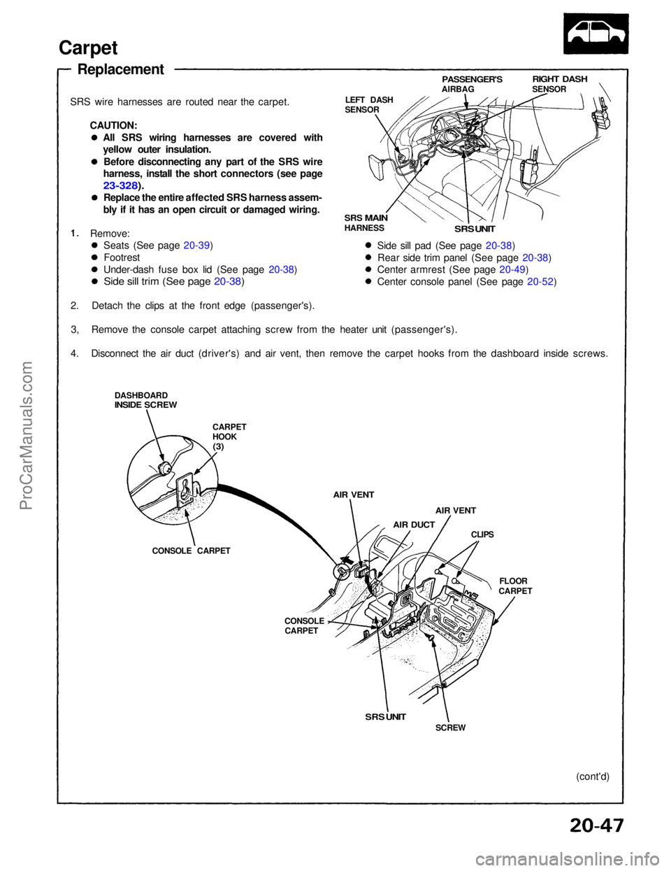
SRS wire harnesses are routed near the carpet. CAUTION:
Remove:
2. Detach the clips at the front edge (passenger's). 3, Remove the console carpet attaching screw from the heater unit (passenger's).
4. Disconnect the air duct (driver's) and air vent, then remove the carpet hooks from the dashboard inside screws.
DASHBOARD
INSIDE SCREW
CARPET
HOOK
(3)
AIR VENT
AIR DUCT
AIR VENT
CLIPS
FLOOR
CARPET
CONSOLE
CARPET
CONSOLE CARPET LEFT DASH
SENSOR
PASSENGER'S
AIRBAG
RIGHT DASH
SENSOR
SRS
MAIN
HARNESS
SRS UNIT
Side sill pad (See page 20-38) Rear side trim panel (See page 20-38)
Center armrest (See page 20-49)
Center console panel (See page 20-52)
SRS UNIT
SCREW
(cont'd)
Seats (See page 20-39)
Footrest
Under-dash fuse box lid (See page 20-38)
Side sill trim (See page 20-38)
All SRS wiring harnesses are covered with
yellow outer insulation.
Before disconnecting any part of the SRS wire
harness, install the short connectors (see page
23-328).
Replace the entire affected SRS harness assem-
bly if it has an open circuit or damaged wiring.ProCarManuals.com
Page 1384 of 1640
Relay and Control Unit Locations
Dashboard
CLIMATE CONTROL UNIT
TURN SIGNAL/HAZARD
RELAY
UNDER-DASH FUSE BOX
INTEGRATED
CONTROL UNIT
DASHBOARD
LOWER COVER
STARTER CUT RELAY
Wire colors: BLK/WHT
BLK/WHT, BLU/GRN,
and BLK/BLUProCarManuals.com
Page 1388 of 1640
Relay and Control Unit Locations
Engine Compartment
REAR WINDOW DEFOGGER
RELAY
ENGINE COMPARTMENT
FUSE/RELAY BOX
ENGINE COMPARTMENT
FAN RELAY
Wire colors: YEL/BLU,
BLK/YEL, WHT/RED,
and WHT/BLU
IGNITION CONTROL
MODULE (ICM)ProCarManuals.com
Page 1389 of 1640
Under-dash Fuse Box
CAUTION:
All SRS wiring harnesses are covered with yellow
outer insulation.
Before disconnecting any part of the SRS wire
harness, install the short connectors (see page
24-10 ('93-'96)).
Replace the entire affected SRS harness assembly if
it has an open circuit or damaged wiring.
SRS MAIN
HARNESS
Removal:
1. Disconnect both the negative cable and positive
cable from the battery.
2.
Carefully remove
the
side
sill
pad
(pull
it up.
rear
end first).
3. Remove the fuse box door.
FUSE BOX
DOOR
SIDE SILL PAD
SIDE SILL TRIM
4. Remove the three screws, then remove the side sill
trim.
5. Remove the under-dash fuse box mounting bolts.
Removal/InstallationProCarManuals.com
Page 1390 of 1640
6. Disconnect the under-dash fuse box connectors.
NOTE: The SRS main harness connector is double
locked. To remove it, first lift the connector lid,
then press the connector tab down and pull the connector out. Installation:
1. Connect the connectors to the under-dash fuse box.
NOTE: To reinstall the SRS main harness connec-
tor, push it into position until it clicks, then close
the connector lid.
2. Install the under-dash fuse box.
3. Install the side sill trim, fuse box door and door sill pad.
4. Connect both the negative cable and positive cable to the battery.
5. Confirm that all systems work properly.
7. Take out the under-dash fuse box.
TAB
LID
SRS FUSE
No. 1 (10 A)
SRS MAIN HARNESS
SIDE SILL TRIM
FUSE BOX
DOOR
SIDE SILL PADProCarManuals.com
Page 1402 of 1640
NOTE: A short to ground in the ORN wire can be caused by a short in any component connected to it.
Vehicle Speed Sensor (VSS) Test
Speedometer does not work.
Inspect No. 2 (15 A) fuse in theunder-dash fuse box before
testing.
Disconnect the 3-P connector at
the
VSS.
Turn the ignition switch ON.
Measure voltage between the
BLK/YEL wire terminal and the
BLK wire terminal in the harness
side of the 3-P connector. Is there battery voltage?
Measure voltage between the
YEL/RED and the BLK wire ter-
minals.
Is there about 5 V?(To next page) Repair open in YEL/RED wire or
short to body ground. View from
terminal side
3-P CONNECTOR
VSS
BLK
Is there continuity?
Repair open BLK/YEL wire, be-
tween the VSS and under-dash
fuse box. Check for continuity between the
BLK terminal and body ground.
Repair open between
the VSS and ground
G101.
(cont'd)ProCarManuals.com
Page 1404 of 1640
Blown No. 5 (10 A) fuse
(In the under-dash fuse box)
Blown No. 34 (15 A) fuse
(In the under-dash fuse box)
Safety indicator input
Safety indicator (Diodes)Brake light failure sensorDoor switch
Trunk latch switch
Retractable headlight control unit
(see page 23-174)
Poor ground
Open circuit, loose or disconnected
terminalsProCarManuals.com