Page 684 of 1640
SRS components are located in this area. Review the SRS component locations, precautions, and procedures in the SRS
section 24 before performing repairs or service.
POWER TRANSISTORBLOWER MOTOR
RECIRCULATION
CONTROL
MOTOR
CONDENSER
FAN MOTOR UNDER-HOOD RELAY BOX A
(CONDENSER FAN RELAY, COMPRESSOR CLUTCH RELAY,
BLOWER MOTOR HIGH RELAY, BLOWER MOTOR RELAY)
UNDER-HOOD
FUSE/RELAY
BOX
HEATER CORE TEMPERATURE SENSOR
CLIMATE CONTROL UNIT VENT DOOR
CONTROL MOTOR
OUTSIDE AIR
TEMPERATURE SENSOR ENGINE COMPARTMENT
FUSE/RELAY BOX
A/C TRIPLE PRESSURE SWITCH
FAN CONTROL UNIT (Fan radiator and con-
denser fans inside car,
behind seats)
EVAPORATOR
TEMPERATURE
SENSOR
IN-CAR
TEMPERATURE
SENSOR
MODE CONTROL
MOTOR
AIR MIX CONTROL MOTOR
SUNLIGHT
SENSORProCarManuals.com
Page 729 of 1640

Troubleshooting
Tips and Precautions
Before Troubleshooting
• Check applicable fuses in the appropriate fuse box.
• Check the battery for damage, state of charge, and
clean and tight connections.
• Check the alternator belt tension.
CAUTION:
• Do not quick-charge a battery unless the battery
ground cable has been disconnected.
Otherwise you will damage the alternator
diodes.
• Do not attempt to crank the engine with the bat-
tery ground cable loosely connected or you will
severely damage the wiring.
Handling Connectors
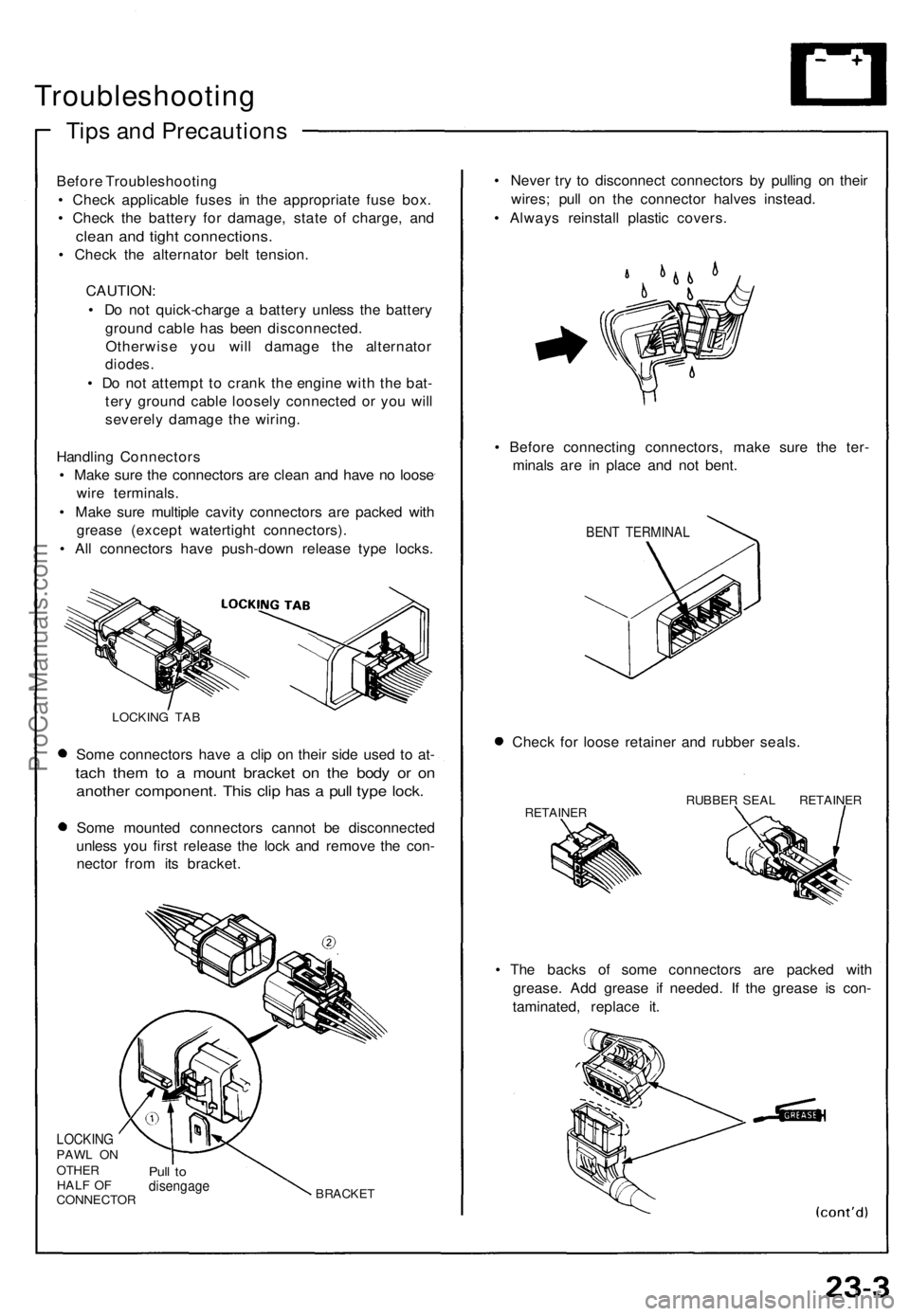
• Make sure the connectors are clean and have no loose
wire terminals.
• Make sure multiple cavity connectors are packed with
grease (except watertight connectors).
• All connectors have push-down release type locks.
LOCKING TAB
Some connectors have a clip on their side used to at-
tach them to a mount bracket on the body or on
another component. This clip has a pull type lock.
Some mounted connectors cannot be disconnected
unless you first release the lock and remove the con-
nector from its bracket.
LOCKING
PAWL ON
OTHER
HALF OF
CONNECTOR
Pull to
disengage
BRACKET
• Never try to disconnect connectors by pulling on their
wires; pull on the connector halves instead.
• Always reinstall plastic covers.
• Before connecting connectors, make sure the ter-
minals are in place and not bent.
BENT TERMINAL
Check for loose retainer and rubber seals.
RETAINER
RUBBER SEAL RETAINER
• The backs of some connectors are packed with
grease. Add grease if needed. If the grease is con-
taminated, replace it.ProCarManuals.com
Page 732 of 1640
Relay and Control Unit Locations
Front Compartment
HORN RELAY
A/C COMPRESSOR CLUTCH
RELAY
RADIATOR FAN
LOW RELAY
RADIATOR FAN
HIGH RELAY
CONDENSER FAN RELAY
UNDER-HOOD RELAY BOX A
LEFT HEADLIGHT RETRACTOR
CUT RELAY
WINDSHIELD WIPER
LOW RELAY
WINDSHIELD WIPER
INTERMITTENT RELAY
POWER AMPLIFIER
RELAY
ABS
REAR FAIL-SAFE RELAY
ABS FRONT
FAIL-SAFE RELAY
HEADLIGHT RELAY
RIGHT HEADLIGHT RETRACTOR RELAY
Wire colors: BLU/GRN,
BRN/WHT, BLU/RED,
GRN/YEL, and BLK
LEFT HEADLIGHT RETRACTOR RELAY
Wire colors: BLU/BLK,
WHT/BLK, GRN/RED,
BLU,
and BLK
RIGHT HEADLIGHT RETRACTOR
CUT RELAY
BLOWER RELAY
BLOWER HIGH RELAY
WINDSHIELD WIPER
HIGH RELAY
WINDSHIELD
WASHER RELAY
UNDER-HOOD
RELAY BOX B
DIMMER RELAY
POWER WINDOW
RELAY
TAILLIGHT RELAY
ABS MOTOR RELAY
UNDER-HOOD FUSE/RELAY BOXProCarManuals.com
Page 733 of 1640
Relay and Control Unit Locations
Dashboard
TURN SIGNAL/HAZARD
RELAY
CLIMATE CONTROL UNIT
UNDER-DASH FUSE BOX
FOOT WELL LIGHT
DASHBOARD
LOWER COVER
INTEGRATED
CONTROL UNIT
SRS UNITProCarManuals.com
Page 737 of 1640
Relay and Control Unit Locations
Engine Compartment
REAR WINDOW DEFOGGER
RELAY
ENGINE COMPARTMENT
FAN RELAY (A/T)
Wire colors: YEL/BLK,
BLU/RED, WHT/GRN,
and WHT/BLU
SPARK PLUG VOLTAGE
DETECTION MODULE
ENGINE COMPARTMENT
FUSE/RELAY BOX
IGNITION CONTROL
MODULE (ICM)ProCarManuals.com
Page 741 of 1640
Under-dash Fus e Bo x
Removal/Installatio n
SRS component s ar e locate d in thi s area . Revie w th e SR S
componen t locations , precautions , an d procedure s in th e
SR S sectio n 24 befor e performin g repair s o r service .
Removal :
1. Disconnec t bot h th e negativ e cabl e an d positiv e
cabl e fro m th e battery .
2 . Carefull y remov e th e sid e sil l pa d (pul l i t up , rea r
en d first) .
3 . Remov e th e fus e bo x door .
FUSE BO XDOO R
SIDE SIL L PA D
SIDE SIL L TRI M
4. Remov e th e thre e screws , the n remov e th e sid e sil l
trim .
5. Remov e th e under-das h fus e bo x mountin g bolts . 6
. Disconnec t th e under-das h fus e bo x connectors .
NOTE : Th e SR S mai n harnes s connecto r i s doubl e
locked . T o remov e it , firs t lif t th e connecto r lid ,
the n pres s th e connecto r ta b dow n an d pul l th e
connecto r out .
TAB
SR S MAI N HARNES S
7. Tak e ou t th e under-das h fus e box .
ProCarManuals.com
Page 742 of 1640
Installation:
1. Connect the connectors to the under-dash fuse
box.
NOTE: To reinstall the SRS main harness connec-
tor, push it into position until it clicks, then close
the connector lid.
2. Install the under-dash fuse box.
3. Install the side sill trim, fuse box door and door sill
pad.
FUSE BOX
DOOR
SIDE SILL PAD
SIDE SILL TRIM
4. Connect both the negative cable and positive cable
to the battery.
5. Confirm that all systems work properly.ProCarManuals.com
Page 748 of 1640

Starting Syste m
Starter Tes t
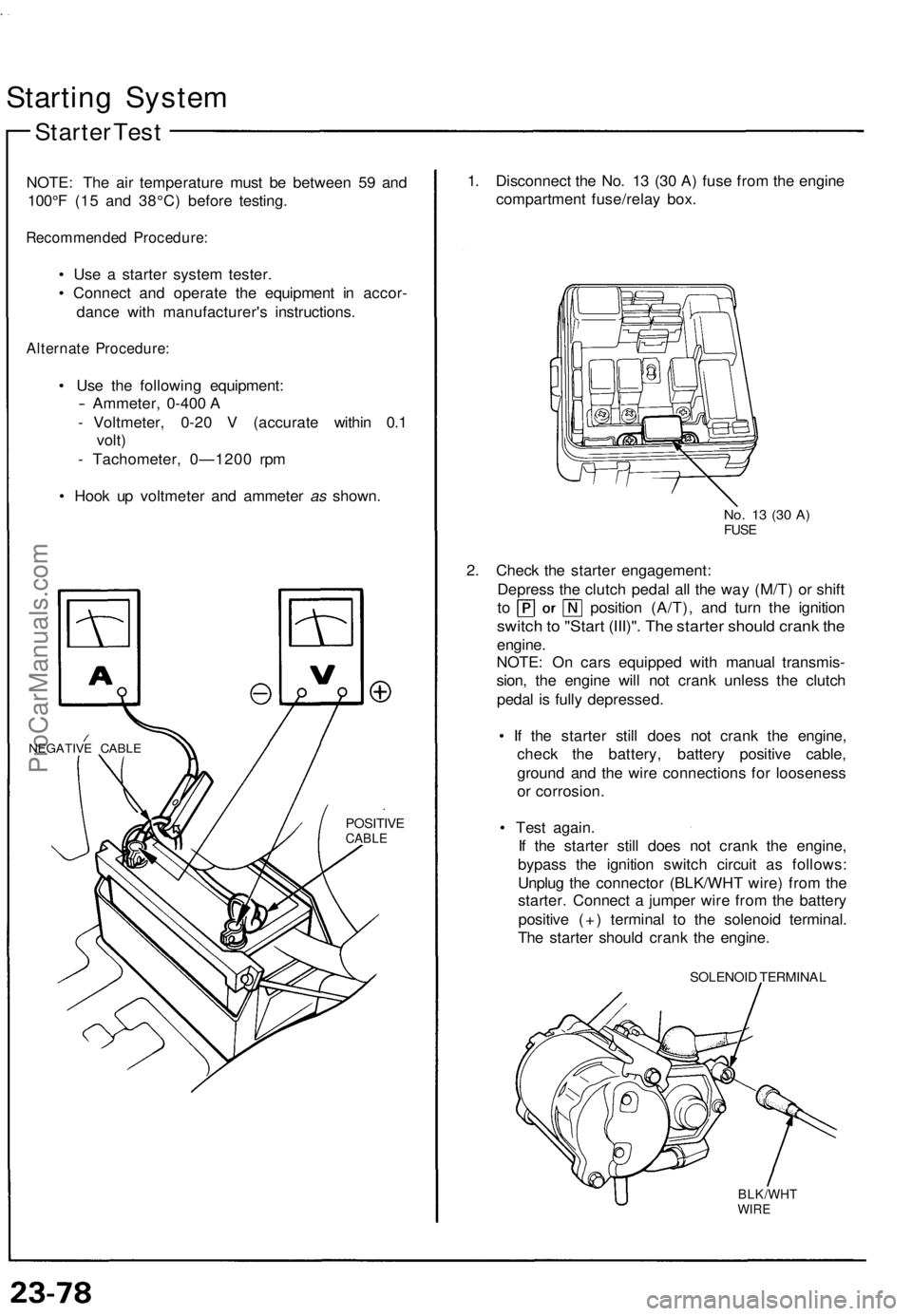
NOTE : Th e ai r temperatur e mus t b e betwee n 5 9 an d
100° F (1 5 an d 38°C ) befor e testing .
Recommende d Procedure :
• Us e a starte r syste m tester .
• Connec t an d operat e th e equipmen t i n accor -
danc e wit h manufacturer' s instructions .
Alternate Procedure :
• Us e th e followin g equipment :
- Ammeter, 0-400 A
- Voltmeter , 0-2 0 V (accurat e withi n 0. 1
volt )
- Tachometer , 0—120 0 rp m
• Hoo k u p voltmete r an d ammete r as shown .
NEGATIV E CABL E
POSITIV ECABLE
1. Disconnec t th e No . 1 3 (3 0 A ) fus e fro m th e engin e
compartmen t fuse/rela y box .
No. 1 3 (3 0 A )FUS E
2. Chec k th e starte r engagement :
Depres s th e clutc h peda l al l th e wa y (M/T ) o r shif t
to positio n (A/T) , an d tur n th e ignitio n
switch to "Star t (III)" . Th e starte r shoul d cran k th e
engine .
NOTE : O n car s equippe d wit h manua l transmis -
sion , th e engin e wil l no t cran k unles s th e clutc h
peda l i s full y depressed .
• I f th e starte r stil l doe s no t cran k th e engine ,
chec k th e battery , batter y positiv e cable ,
groun d an d th e wir e connection s fo r loosenes s
o r corrosion .
• Tes t again .
I f th e starte r stil l doe s no t cran k th e engine ,
bypas s th e ignitio n switc h circui t a s follows :
Unplu g th e connecto r (BLK/WH T wire ) fro m th e
starter . Connec t a jumpe r wir e fro m th e batter y
positiv e (+ ) termina l t o th e solenoi d terminal .
Th e starte r shoul d cran k th e engine .
SOLENOI D TERMINA L
BLK/WHTWIRE
ProCarManuals.com