Page 265 of 1640

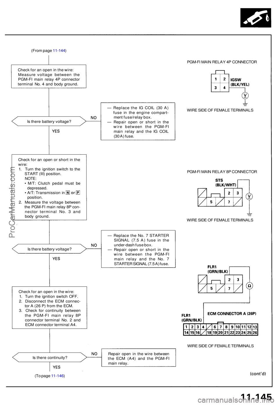
(From pag e 11-144 )
Chec k fo r a n ope n in th e wire :
Measur e voltag e betwee n th e
PGM-F I mai n rela y 4 P connecto r
termina l No . 4 an d bod y ground . PGM-F
I MAI N RELA Y 4 P CONNECTO R
I s ther e batter y voltage ? —
Replac e th e I G COI L (3 0 A )
fus e i n th e engin e compart -
men t fuse/rela y box .
— Repai r ope n o r shor t i n th e
wir e betwee n th e PGM-F I
mai n rela y an d th e I G COI L
(3 0 A ) fuse . WIR
E SID E O F FEMAL E TERMINAL S
Chec k fo r a n ope n o r shor t i n th e
wire :
1 . Tur n th e ignitio n switc h t o th e
STAR T (III ) position .
NOTE:• M/T : Clutc h peda l mus t b e
depressed .
• A/T : Transmissio n in
position .
2 . Measur e th e voltag e betwee n
th e PGM-F I mai n rela y 8 P con -
necto r termina l No . 3 an d
bod y ground . PGM-F
I MAI N RELA Y 8 P CONNECTO R
WIR E SID E O F FEMAL E TERMINAL S
I s ther e batter y voltage ? —
Replac e th e No . 7 STARTE R
SIGNA L (7. 5 A ) fus e i n th e
under-das h fus e box .
— Repai r ope n o r shor t i n th e
wir e betwee n th e PGM-F I
mai n rela y an d th e No . 7
STARTE R SIGNA L (7. 5 A ) fuse .
Chec k fo r a n ope n in th e wire :
1 . Tur n th e ignitio n switc h OFF .
2 . Disconnec t th e EC M connec -
to r A (2 6 P ) fro m th e ECM .
3 . Chec k fo r continuit y betwee n
th e PGM-F I mai n rela y 8 P
connecto r termina l No . 2 an d
EC M connecto r termina l A4 .
WIRE SID E O F FEMAL E TERMINAL S
I s ther e continuity ? Repai
r ope n i n th e wir e betwee n
th e EC M (A4 ) an d th e PGM-F I
mai n relay .
(T o pag e 11-146 )
ProCarManuals.com
Page 417 of 1640
GAUGE ASSEMBLY
EPS INDICATOR LIGHT
UNDER-HOOD FUSE/RELAY BOX
No. 2 (15 A)
IG SW (50 A)
CLOCK (7.5 A)
E-PS
(50 A)
UNDER-DASH FUSE BOX
No. 5 (15 A)ProCarManuals.com
Page 422 of 1640
Diagnostic Trouble Code (DTC) Indication
Example:
1.3 seconds
DTC Indication Pattern:
DTC:
11
DTC:
12
EPS Indicator light ON
EPS Indicator light OFF
0.28 seconds
Repeat
Connect the SCS Turn the ignition
service connector switch ON (II)
0.36 seconds 1.3 seconds
• The DTC is indicated by a series of long and short blinks. One long blink equals 10 short blinks.
Add the long and short blinks together to determine the DTC.
• The DTCs are repeated sequentially beginning with the lowest number.
4. Remove the SCS service connector.
NOTE: The Malfunction Indicator Lamp (MIL) will stay on after the engine is started if the SCS service connector is
connected.
5. Remove the CLOCK (7.5 A) fuse in the under-hood fuse/relay box for more than 10 seconds to erase the EPS control
unit memory.ProCarManuals.com
Page 492 of 1640
Illustrated Index
The accumulator contains high-pressure nitrogen gas; do not puncture, expose to flame or attempt to
disassemble the accumulator or it may explode; severe personal injury may result.
HYDRAULIC SYSTEM
Relieving Accumulator/line pressure, page 19-62 ('91-'92) ('93-'96)
MASTER CYLINDER
Index/Torque, page 19-12
Inspection, page 19-13
ABS CONTROL UNIT Replacement, page 19-70
BRAKE BOOSTER
Tests, page 19-14 Pushrod clearance adjustment, page 19-15
UNDER-HOOD
RELAY BOX B
UNDER-HOOD
FUSE/RELAY BOX
REAR WHEEL SENSOR
Inspection, page 19-71
Replacement, page 19-72
POWER UNIT
Torque/Inspection, page 19-66
ACCUMULATOR/PRESSURE SWITCHIndex/Torque, page 19-67 FRONT WHEEL SENSOR
Inspection, page 19-71
Replacement, page 19-72
MODULATOR/SOLENOID UNIT
Index/Torque, page 19-63 ('91-'92) ('93-'96)
Solenoid Leak Test, page 19-64 ('91-'92) ('93-'96)
ProCarManuals.com
Page 531 of 1640

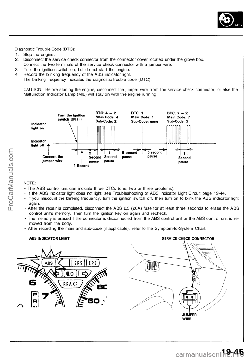
Diagnostic Trouble Code (DTC):
1. Stop the engine.
2. Disconnect the service check connector from the connector cover located under the glove box.
Connect the two terminals of the service check connector with a jumper wire.
3. Turn the ignition switch on, but do not start the engine.
4. Record the blinking frequency of the ABS indicator light.
The blinking frequency indicates the diagnostic trouble code (DTC).
CAUTION: Before starting the engine, disconnect the jumper wire from the service check connector, or else the
Malfunction Indicator Lamp (MIL) will stay on with the engine running.
NOTE:
• The ABS control unit can indicate three DTCs (one, two or three problems).
• If the ABS indicator light does not light, see Troubleshooting of ABS Indicator Light Circuit page 19-44.
• If you miscount the blinking frequency, turn the ignition switch off, then turn on to blink the ABS indicator light
again.
• After the repair is completed, disconnect the ABS 2,3 (20A) fuse for at least three seconds to erase the ABS
control unit's memory. Then turn the ignition key on again and recheck.
• The memory is erased if the connector is disconnected from the ABS control unit or the ABS control unit is re-
moved from the body.
• After recording the main and sub-code (if applicable), refer to the Symptom-to-System Chart.ProCarManuals.com
Page 537 of 1640

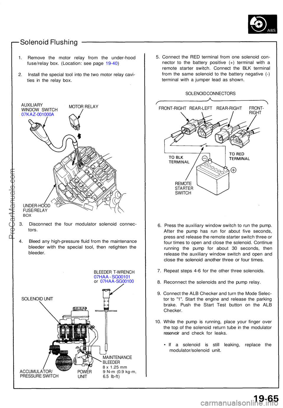
Solenoid Flushin g
1. Remov e th e moto r rela y fro m th e under-hoo d
fuse/rela y box . (Location : se e pag e 19-40 )
2 . Instal l th e specia l too l int o th e tw o moto r rela y cavi -
tie s i n th e rela y box .
AUXILIAR Y
WINDO W SWITC H
07KAZ-001000 A
MOTOR RELA Y
UNDER-HOO DFUSE/RELAYBOX
3. Disconnec t th e fou r modulato r solenoi d connec -
tors .
4 . Blee d an y high-pressur e flui d fro m th e maintenanc e
bleeder wit h th e specia l tool , the n retighte n th e
bleeder .
SOLENOI D UNI T
BLEEDE R T-WRENC H07HAA - SG0010 1or 07HA A-SG0010 0
ACCUMULATOR /
PRESSUR E SWITC HPOWERUNIT
MAINTENANC EBLEEDER8 x 1.2 5 mm9 N- m (0. 9 kg-m ,6.5 Ib-ft )
5. Connec t th e RE D termina l fro m on e solenoi d con -
necto r t o th e batter y positiv e (+ ) termina l wit h a
remot e starte r switch . Connec t th e BL K termina l
fro m th e sam e solenoi d t o th e batter y negativ e (- )
termina l wit h a jumpe r lea d a s shown .
SOLENOI D CONNECTOR S
FRONT-RIGH T REAR-LEF T REAR-RIGH T
FRONT-RIGHT
REMOT ESTARTE RSWITCH
6. Pres s th e auxiliar y windo w switc h t o ru n th e pump .
Afte r th e pum p ha s ru n fo r abou t fiv e seconds ,
pres s an d releas e th e remot e starte r switc h thre e o r
fou r time s t o ope n an d clos e th e solenoid . Continu e
runnin g th e pum p fo r abou t 3 0 seconds , the n
releas e th e auxiliar y windo w switc h an d ope n an d
clos e th e solenoi d anothe r thre e o r fou r times .
7. Repea t step s 4- 6 fo r th e othe r thre e solenoids .
8 . Reconnec t th e solenoid s an d th e pum p relay .
9 . Connec t th e AL B Checke r an d tur n th e Mod e Selec -
to r t o "1" . Star t th e engin e an d releas e th e parkin g
brake . Pus h th e Star t Tes t butto n o n th e AL B
Checker .
10. Whil e th e pum p i s running , plac e you r finge r ove r
th e to p o f th e solenoi d retur n tub e in th e modulato r
reservoi r an d chec k fo r leaks .
• I f a solenoi d i s stil l leaking , replac e th e
modulator/solenoi d
unit.
ProCarManuals.com
Page 595 of 1640

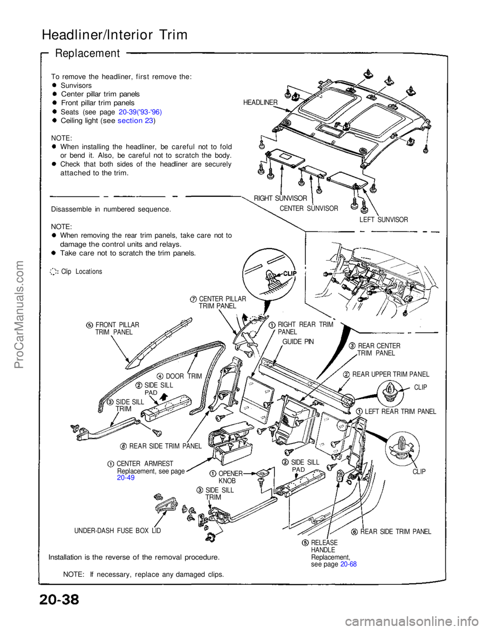
Headliner/lnterior Trim
Replacement
To remove the headliner, first remove the: Sunvisors
Center pillar trim panels
Front pillar trim panels
Seats (see page 20-39('93-'96)
Ceiling light (see section 23)
NOTE:
When installing the headliner, be careful not to fold
or bend it. Also, be careful not to scratch the body.
Check that both sides of the headliner are securely
attached to the trim.
Disassemble in numbered sequence.
NOTE: When removing the rear trim panels, take care not to
damage the control units and relays.
Take care not to scratch the trim panels.
Clip Locations
CENTER PILLAR
TRIM PANEL
FRONT PILLAR
TRIM PANEL
DOOR TRIM
SIDE SILL
PAD
SIDE SILL
TRIM
REAR SIDE TRIM PANEL
CENTER ARMREST
Replacement, see page
20-49
OPENER
KNOB
SIDE SILL
TRIM
UNDER-DASH FUSE BOX LID
Installation is the reverse of the removal procedure.
NOTE: If necessary, replace any damaged clips.
RELEASE
HANDLE
Replacement,
see page 20-68
REAR SIDE TRIM PANEL CLIP
SIDE SILL
PAD
LEFT REAR TRIM PANEL
CLIP
REAR UPPER TRIM PANEL REAR CENTER
TRIM PANEL
GUIDE PIN
RIGHT REAR TRIM
PANEL LEFT SUNVISOR
CENTER SUNVISOR
RIGHT SUNVISOR
HEADLINERProCarManuals.com
Page 604 of 1640
Carpet
Replacement
SRS components are located in this area. Review the SRS component locations, precautions, and procedures in the SRS
section (24) before performing repairs or service.
DASHBOARD
INSIDE SCREW
CARPET
HOOK
(3)
AIR VENT
AM VENT
AIR DUCT
CUPS
FLOOR
CARPET
CONSOLE
CARPET
CONSOLE CARPET
SRS UNIT
SCREW
(cont'd)
1. Remove:
Seats (see page 20-39('93-'96), 38('91-'92)
Footrest
Under-dash fuse box lid (see page 20-38('93-'96),37('91-'92)
Side sill trim (see page 20-38 ('93-'96), 37('91-'92)
Side sill pad (see page 20-38('93-'96), 37('91-'92)
Rear side trim panel (see page 20-38('93-'96), 37('91-'92)
Center armrest (see page 20-49('94-'96)('91-'93)
Center console panel (see page 20-52('94-'96)('91-'93)
2. Detach the clips at The front edge (passenger's).
3. Remove the console carpet attaching screw from the heater unit (passenger's).
4. Disconnect the air duct (driver's) and air vent, then remove the carpet hooks from the dashboard inside screws.ProCarManuals.com