1991 ACURA NSX light
[x] Cancel search: lightPage 1154 of 1640
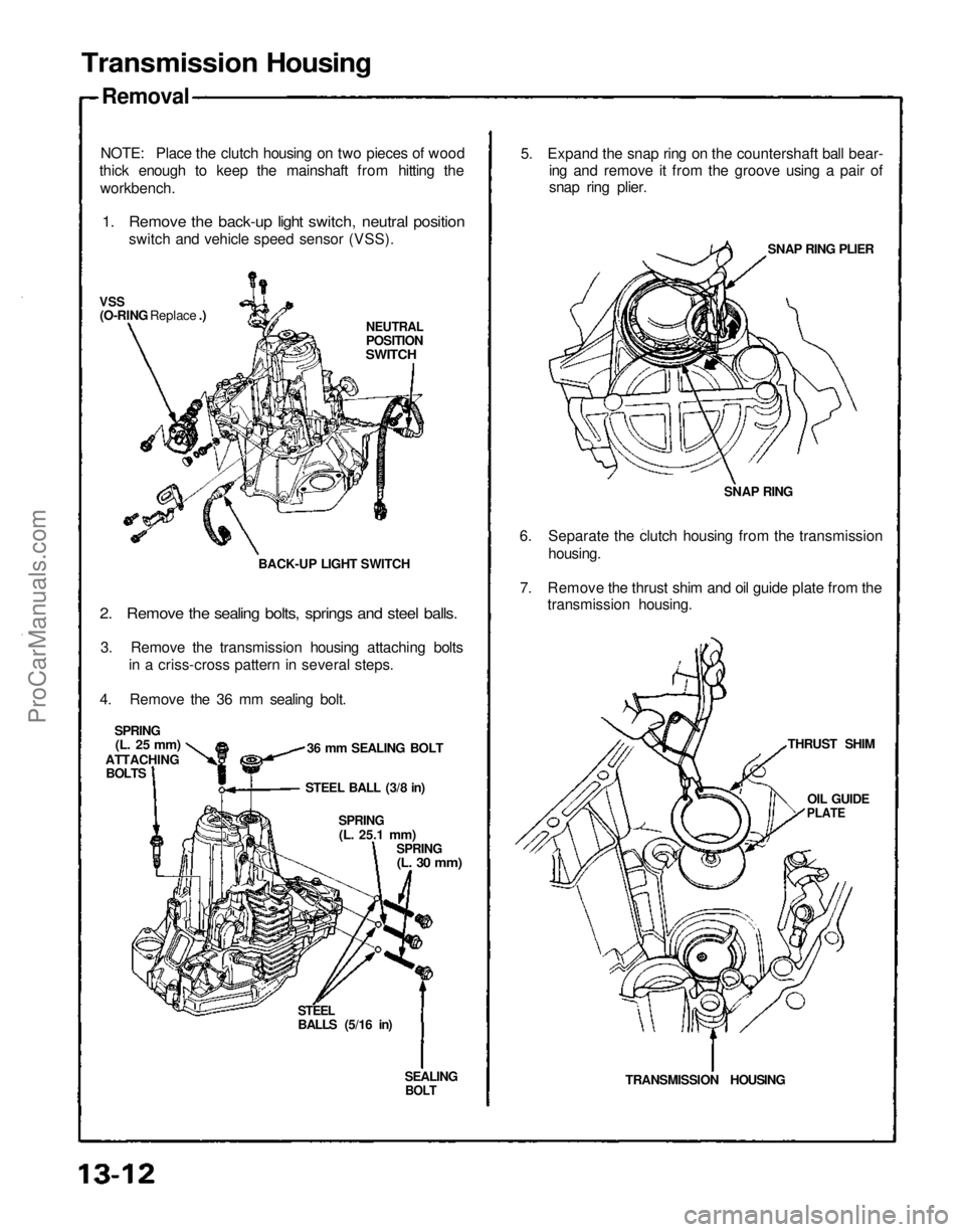
SEALING
BOLT
STEEL
BALLS (5/16 in)
Transmission Housing
Removal
NOTE: Place the clutch housing on two pieces of wood
thick enough to keep the mainshaft from hitting the
workbench.
1. Remove the back-up light switch, neutral position
switch and vehicle speed sensor (VSS).
NEUTRAL
POSITION
SWITCH
VSS
(O-RING Replace .)
BACK-UP LIGHT SWITCH36 mm SEALING BOLT
SPRING
(L. 25 mm)
ATTACHING BOLTS
2. Remove the sealing bolts, springs and steel balls.
3. Remove the transmission housing attaching bolts in a criss-cross pattern in several steps.
4. Remove the 36 mm sealing bolt.
STEEL BALL (3/8 in)
SPRING
(L.
25.1
mm)
SPRING
(L. 30 mm)
TRANSMISSION HOUSINGTHRUST SHIM
OIL GUIDE
PLATE
6. Separate the clutch housing from the transmission
housing. SNAP RINGSNAP RING PLIER
5. Expand the snap ring on the countershaft ball bear-
ing and remove it from the groove using a pair of
snap ring plier.
7. Remove the thrust shim and oil guide plate from the transmission housing.ProCarManuals.com
Page 1159 of 1640
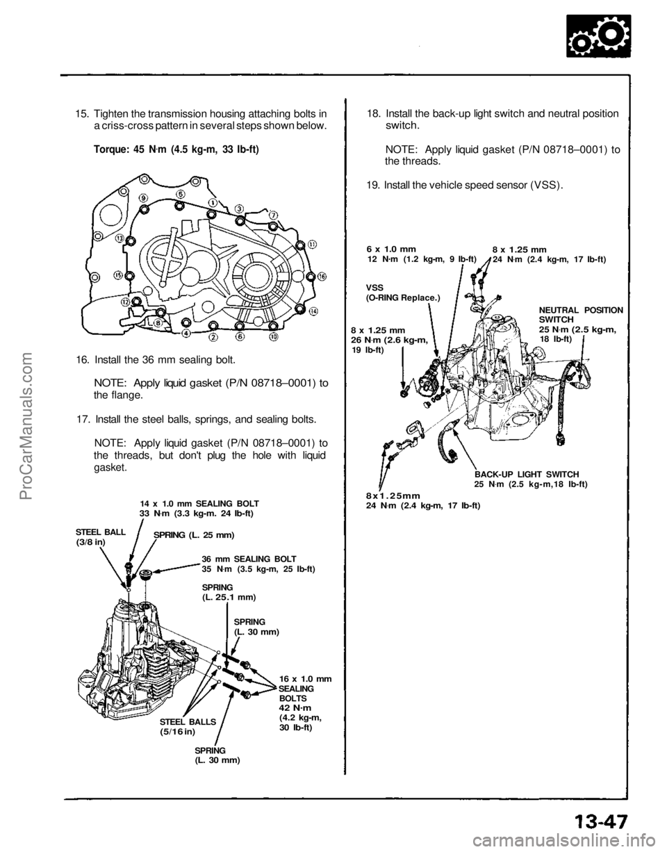
15. Tighten the transmission housing attaching bolts in
a criss-cross pattern in several steps shown below.
Torque: 45 N .
m (4.5 kg-m, 33 Ib-ft)
16. Install the 36 mm sealing bolt.
NOTE: Apply liquid gasket (P/N 08718–0001) to
the flange.
17. Install the steel balls, springs, and sealing bolts. NOTE: Apply liquid gasket (P/N 08718–0001) to
the threads, but don't plug the hole with liquid
gasket.
14 x 1.0 mm SEALING BOLT
33 N .
m (3.3 kg-m. 24 Ib-ft)
STEEL BALL
(3/8
in)
SPRING (L. 25 mm)
36 mm SEALING BOLT
35 N.
m (3.5 kg-m, 25 Ib-ft)
SPRING
(L.
25.1
mm)
SPRING
(L. 30 mm)
16 x 1.0 mm
SEALING BOLTS
42 N .
m
(4.2 kg-m,
30 Ib-ft)
STEEL BALLS
(5/16
in)
SPRING
(L. 30 mm)
18. Install the back-up light switch and neutral position
switch.
NOTE: Apply liquid gasket (P/N 08718–0001) to
the threads.
19. Install the vehicle speed sensor (VSS).
6 x 1.0 mm
12 N .
m (1.2 kg-m, 9 Ib-ft)
VSS
(O-RING Replace.)
8 x
1.25
mm
24 N .
m (2.4 kg-m, 17 Ib-ft)
NEUTRAL POSITION
SWITCH
25 N.
m
(2.5 kg-m,
18 Ib-ft)
BACK-UP LIGHT SWITCH
25 N .
m (2.5 kg-m,18 Ib-ft)
8x1.25 mm
24 N .
m (2.4 kg-m, 17 Ib-ft)
8 x
1.25
mm
26 N
.
m
(2.6 kg-m,
19 Ib-ft)ProCarManuals.com
Page 1163 of 1640
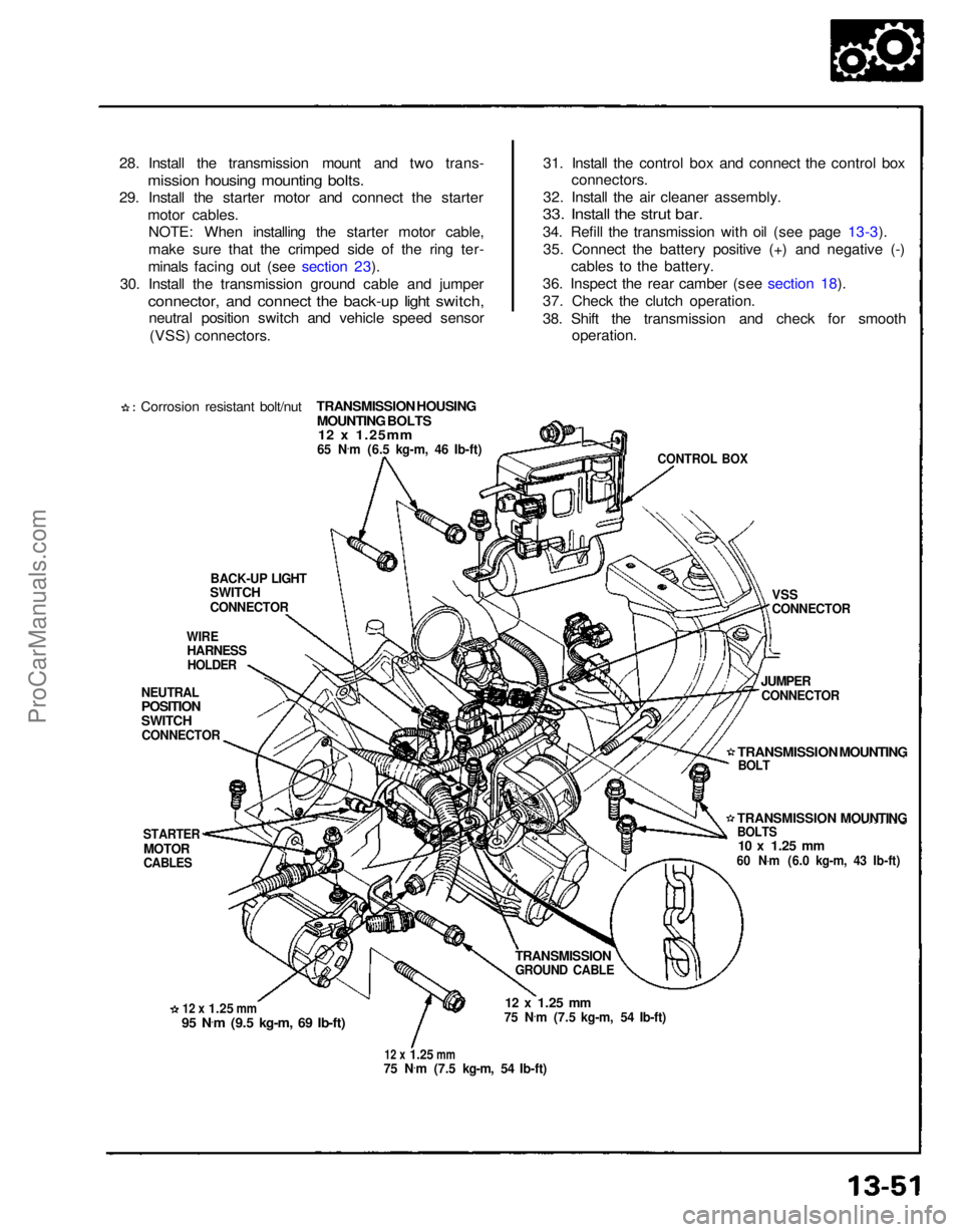
28. Install the transmission mount and two trans-
mission housing mounting bolts.
29. Install the starter motor and connect the starter
motor cables.NOTE: When installing the starter motor cable,
make sure that the crimped side of the ring ter-
minals facing out (see section 23).
30. Install the transmission ground cable and jumper
connector, and connect the back-up light switch,
neutral position switch and vehicle speed sensor
(VSS) connectors.
Corrosion resistant bolt/nut
TRANSMISSION HOUSING
MOUNTING BOLTS12 x 1.25mm
65 N
.
m (6.5 kg-m, 46 Ib-ft)
BACK-UP LIGHT
SWITCH
CONNECTOR
WIRE
HARNESS
HOLDER
NEUTRAL
POSITION
SWITCH
CONNECTOR
STARTER
MOTOR
CABLES
12 x
1.25
mm
95 N
.
m (9.5 kg-m, 69 Ib-ft)
12 x
1.25
mm
75 N
.
m (7.5 kg-m, 54 Ib-ft)
12 x
1.25
mm
75 N .
m (7.5 kg-m, 54 Ib-ft)
TRANSMISSION
GROUND CABLE
TRANSMISSION MOUNTING
BOLTS
10 x
1.25
mm
60 N .
m (6.0 kg-m, 43 Ib-ft)
JUMPER
CONNECTOR
VSS
CONNECTOR
CONTROL BOX
31. Install the control box and connect the control box
connectors.
32. Install the air cleaner assembly.
33. Install the strut bar.
34. Refill the transmission with oil (see page 13-3).
35. Connect the battery positive (+) and negative (-) cables to the battery.
36. Inspect the rear camber (see section 18).
37. Check the clutch operation.
38. Shift the transmission and check for smooth operation.
TRANSMISSION MOUNTING
BOLTProCarManuals.com
Page 1166 of 1640
REVERSE,
Description
(cont'd)
AUTOMATIC TRANSAXLE (A/T) GEAR POSITION INDICATOR
A/T gear position indicator in the instrument panel shows what gear has been selected without having to look down at
the console.
ATF COOLER
With this mid-engine type car, the radiator is mounted at the front of the car, so the ATF cooler is installed directly on
the transmission housing. Position
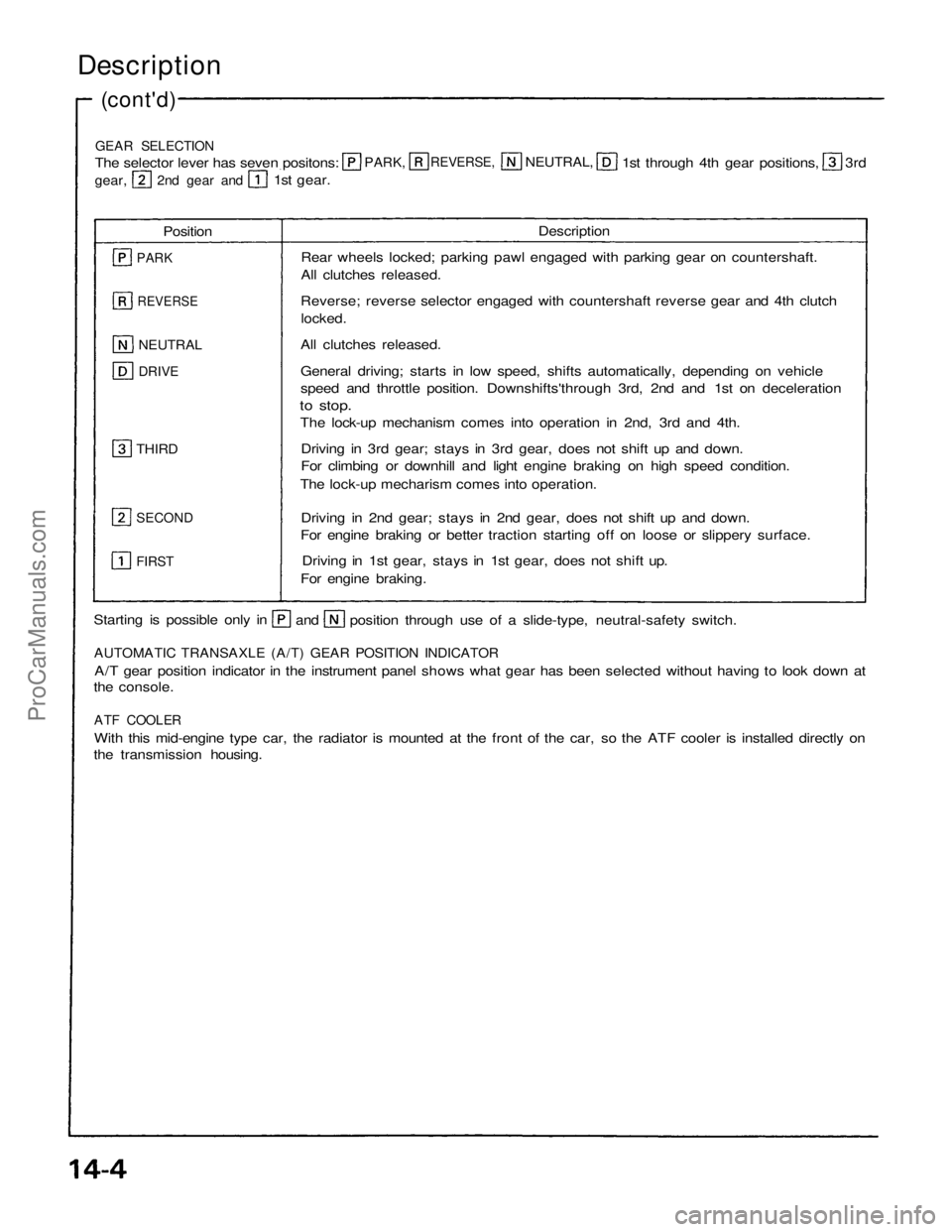
Description
PARK
REVERSE
NEUTRAL
DRIVE
THIRD
SECOND
FIRST
Rear wheels locked; parking pawl engaged with parking gear on countershaft.
All clutches released.
Reverse; reverse selector engaged with countershaft reverse gear and 4th clutch locked.
All clutches released.
General driving; starts in low speed, shifts automatically, depending on vehicle
speed and throttle position. Downshifts'through 3rd, 2nd and 1st on deceleration
to stop.
The lock-up mechanism comes into operation in 2nd, 3rd and 4th.
Driving in 3rd gear; stays in 3rd gear, does not shift up and down.
For climbing or downhill and light engine braking on high speed condition.
The lock-up mecharism comes into operation.
Driving in 2nd gear; stays in 2nd gear, does not shift up and down.
For engine braking or better traction starting off on loose or slippery surface.
Driving in 1st gear, stays in 1st gear, does not shift up.
For engine braking.
GEAR SELECTION
The selector lever has seven positons:
PARK,
NEUTRAL,
1st through 4th gear positions,
3rd
gear,
2nd gear and
1st gear.
Starting is possible only in
and
position through use of a slide-type, neutral-safety switch.
ProCarManuals.com
Page 1202 of 1640
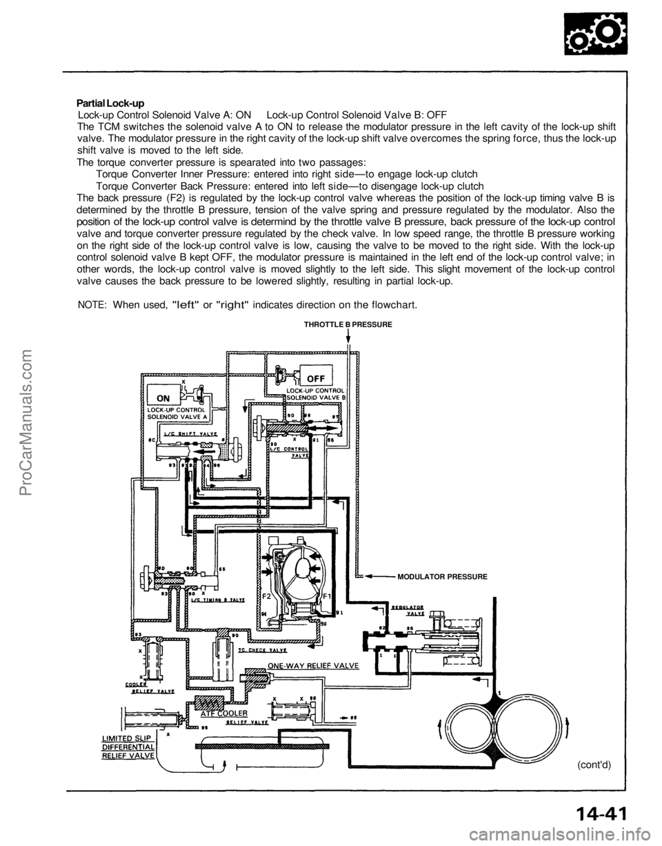
Partial Lock-up
Lock-up Control Solenoid Valve A: ON Lock-up Control Solenoid Valve B: OFF
The TCM switches the solenoid valve A to ON to release the modulator pressure in the left cavity of the lock-up shift
valve. The modulator pressure in the right cavity of the lock-up shift valve overcomes the spring force, thus the lock-up
shift valve is moved to the left side.
The torque converter pressure is spearated into two passages:
Torque Converter Inner Pressure: entered into right side—to engage lock-up clutch
Torque Converter Back Pressure: entered into left side—to disengage lock-up clutch
The back pressure (F2) is regulated by the lock-up control valve whereas the position of the lock-up timing valve B is
determined by the throttle B pressure, tension of the valve spring and pressure regulated by the modulator. Also the
position of the lock-up control valve is determind by the throttle valve B pressure, back pressure of the lock-up control
valve and torque converter pressure regulated by the check valve. In low speed range, the throttle B pressure working
on the right side of the lock-up control valve is low, causing the valve to be moved to the right side. With the lock-up
control solenoid valve B kept OFF, the modulator pressure is maintained in the left end of the lock-up control valve; in
other words, the lock-up control valve is moved slightly to the left side. This slight movement of the lock-up control
valve causes the back pressure to be lowered slightly, resulting in partial lock-up.
NOTE:
When used,
"left"
or
"right"
indicates direction
on the
flowchart.
THROTTLE B PRESSURE
MODULATOR PRESSURE
(cont'd)ProCarManuals.com
Page 1205 of 1640
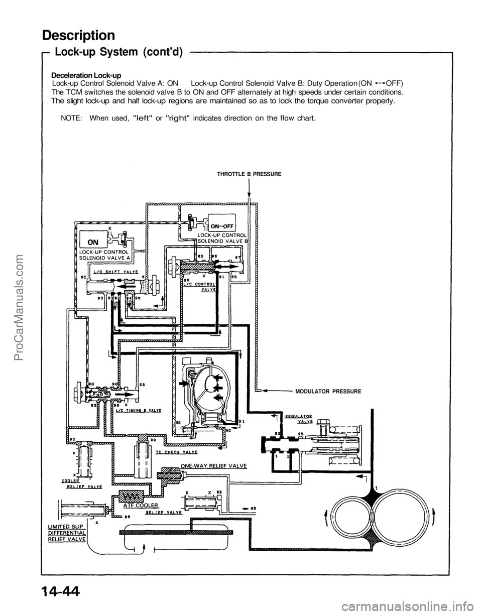
Description
Lock-up System (cont'd)
Deceleration Lock-up
Lock-up Control Solenoid Valve A: ON Lock-up Control Solenoid Valve B: Duty Operation (ON OFF)
The TCM switches the solenoid valve B to ON and OFF alternately at high speeds under certain conditions.
The slight lock-up and half lock-up regions are maintained so as to lock the torque converter properly.
NOTE:
When used,
"left"
or
"right"
indicates direction
on the
flow chart.
MODULATOR PRESSURE
THROTTLE B PRESSUREProCarManuals.com
Page 1208 of 1640
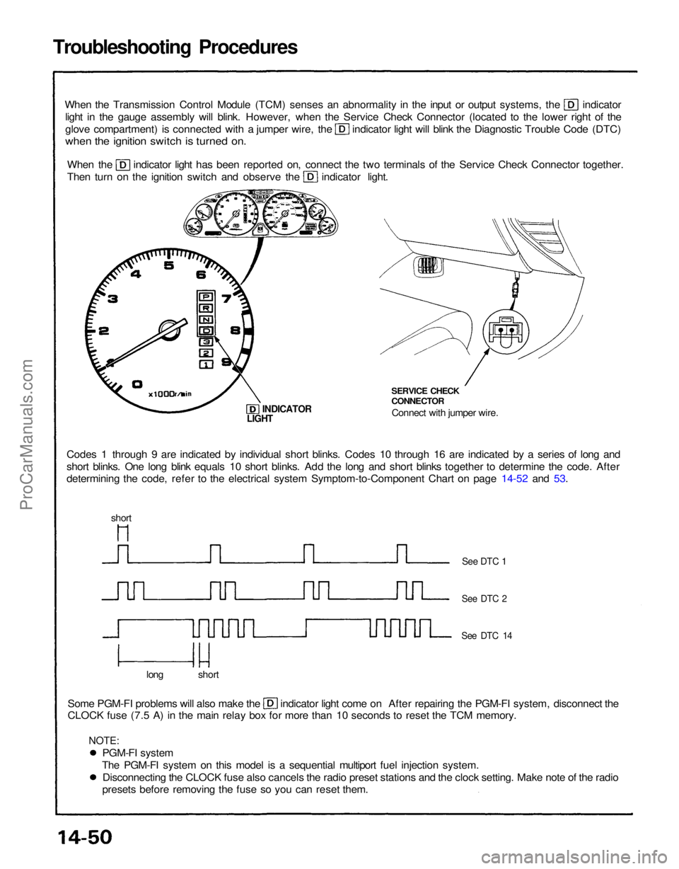
Troubleshooting Procedures
When the Transmission Control Module (TCM) senses an abnormality in the input or output systems, the indicator
light in the gauge assembly will blink. However, when the Service Check Connector (located to the lower right of the glove compartment) is connected with a jumper wire, the indicator light will blink the Diagnostic Trouble Code (DTC)
when the ignition switch is turned on.
When the indicator light has been reported on, connect the two terminals of the Service Check Connector together.
Then turn on the ignition switch and observe the indicator light.
Codes 1 through 9 are indicated by individual short blinks. Codes 10 through 16 are indicated by a series of long and
short blinks. One long blink equals 10 short blinks. Add the long and short blinks together to determine the code. After
determining the code, refer to the electrical system Symptom-to-Component Chart on page 14-52 and 53. SERVICE CHECK
CONNECTOR
Connect with jumper wire.
INDICATOR
Some PGM-FI problems will also make the indicator light come on After repairing the PGM-FI system, disconnect the
CLOCK fuse (7.5 A) in the main relay box for more than 10 seconds to reset the TCM memory.
long short
See DTC 1
See DTC 2
See DTC 14
LIGHT
short
PGM-FI system
The PGM-FI system on this model is a sequential multiport fuel injection system. Disconnecting the CLOCK fuse also cancels the radio preset stations and the clock setting. Make note of the radio
presets before removing the fuse so you can reset them.
NOTE:ProCarManuals.com
Page 1210 of 1640
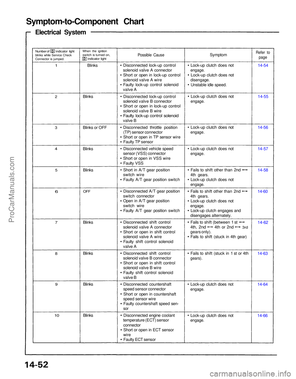
Symptom-to-Component Chart
Electrical System
Number of indicator light
blinks while Service Check
Connector is jumped.
When the ignition
switch is turned on,
indicator light
1
Blinks
Possible Cause
Symptom
Lock-up clutch does not
engage.
Lock-up clutch does not
disengage.
Unstable idle speed.
Refer to
page
14-54
14-55
14-56
14-57
14-58
14-60
14-62
14-63
14-64
14-66
Lock-up clutch does not
engage.
Lock-up clutch does not
engage.
Fails to shift (stuck in 1 st or 4th
gears).
Fails to shift other than 2nd
4th gears.
Lock-up clutch does not
engage.
Lock-up clutch engages and
disengages alternately. Fails to shift other than 2nd
4th gears.
Lock-up clutch does not
engage.
Lock-up clutch does not
engage.
Lock-up clutch does not
engage.
Lock-up clutch does not
engage.
Disconnected lock-up control
solenoid valve A connector Short or open in lock-up control
solenoid valve A wire
Faulty lock-up control solenoid
valve A
Disconnected lock-up control
solenoid valve B connector Short or open in lock-up control
solenoid valve B wire
Faulty lock-up control solenoid
valve B
Disconnected throttle position(TP) sensor connector
Short or open in TP sensor wire
Faulty TP sensor
Disconnected vehicle speed
sensor (VSS) connector
Short or open in VSS wire
Faulty VSS
Short in A/T gear position
switch wire
Faulty A/T gear position switch
Disconnected A/T gear position
switch connector
Open in A/T gear position
switch wire Faulty A/T gear position switch
Disconnected shift control
solenoid valve A connector Short or open in shift control
solenoid valve A wire
Faulty shift control solenoid
valve A
Disconnected shift control
solenoid valve B connector
Short or open in shift control
solenoid valve B wire
Faulty shift control solenoid
valve B
Disconnected countershaft
speed sensor connector
Short or open in countershaft
speed sensor wire Faulty countershaft speed sen-
sor
Disconnected engine coolant
temperature (ECT) sensor
connectorShort or open in ECT sensor
wire Faulty ECT sensor
Blinks
10
9
Blinks
Blinks
8
7
Blinks
6
OFF
Blinks
5
4
Blinks
3
Blinks or OFF Blinks
2
Fails to shift (between 1 st
4th,
2nd
4th or 2nd
3rd
gears only).
Fails to shift (stuck in 4th gear)ProCarManuals.com