Page 1347 of 1640
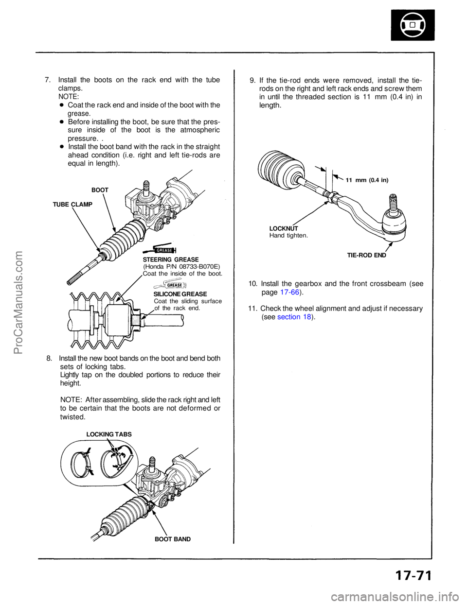
7. Install the boots on the rack end with the tube
clamps.
NOTE:
BOOT
TUBE CLAMP
STEERING GREASE
(Honda P/N 08733-B070E)
Coat the inside of the boot.
SILICONE GREASECoat the sliding surface of the rack end.
8. Install the new boot bands on the boot and bend both sets of locking tabs.
Lightly tap on the doubled portions to reduce their
height.
NOTE: After assembling, slide the rack right and left
to be certain that the boots are not deformed or
twisted. 9. If the tie-rod ends were removed, install the tie-
rods on the right and left rack ends and screw them
in until the threaded section is 11 mm (0.4 in) in
length.
10. Install the gearbox and the front crossbeam (see page 17-66).
11. Check the wheel alignment and adjust if necessary (see section 18).
BOOT BAND
LOCKING TABS
11 mm
(0.4
in)
LOCKNUT
Hand tighten.
TIE-ROD END
Coat the rack end and inside of the boot with the
grease.
Before installing the boot, be sure that the pres-
sure inside of the boot is the atmospheric
pressure. .
Install the boot band with the rack in the straight
ahead condition (i.e. right and left tie-rods are
equal in length).ProCarManuals.com
Page 1349 of 1640
Power Unit
Replacement
1. Remove the floor mat and speaker cover.
2. Disconnect the connector from the speaker and re- move the speaker by removing the bolt and nut.
SPEAKER COVER 5. Remove the power unit by disconnecting the con-
nector.
10 N.m
(1.0 kg-m, 7 lb-ft)
3. Remove the power unit bracket.
4. Bend terminal nut tabs back and remove the ter- minal nuts and disconnect the cables from the
power unit terminals.
Installation is the reverse order of removal.
NOTE:
SPEAKER
TERMINAL NUT
10 N ·
m
(1.0 kg-m, 7 Ib-ft)
BRACKET
POWER UNIT
10 N
·
m
(1.0 kg-m,
7 Ib-ft)
POWER UNIT
After tightening the terminal nuts, bend up the
terminal nut tabs against the nut securely.
Turn the ignition switch ON and check the EPS
indicator light for operation.ProCarManuals.com
Page 1350 of 1640
EPS Control unit
Replacement
CAUTION: Be careful not to damage the SRS wire
harnesses when servicing the control unit. 1. Remove the dashboard lower cover and glove box
and disconnect the light connector.
3. Disconnect the connectors from the EPS control
unit by removing the wire harness band.
EPS CONTROL UNIT
4. Remove the power window control unit by pulling it
toward you, then remove the EPS control unit.
5. Installation is the reverse of the removal procedure.
NOTE: Turn the ignition switch ON and check the
EPS indicator light for operation.
HEATER DUCT
2. Move the heater duct right then remove the heater
duct.
DASHBOARD LOWER COVER
GLOVE BOX
EPS CONTROL UNIT
POWER WINDOW CONTROL
UNIT
10 N ·
m
(1.0 kg-m, 7 Ib-ft)
All SRS wire harnesses and connectors
are colored yellow. Do not use electrical test equipment
on these circuits.
CONNECTORSProCarManuals.com
Page 1352 of 1640
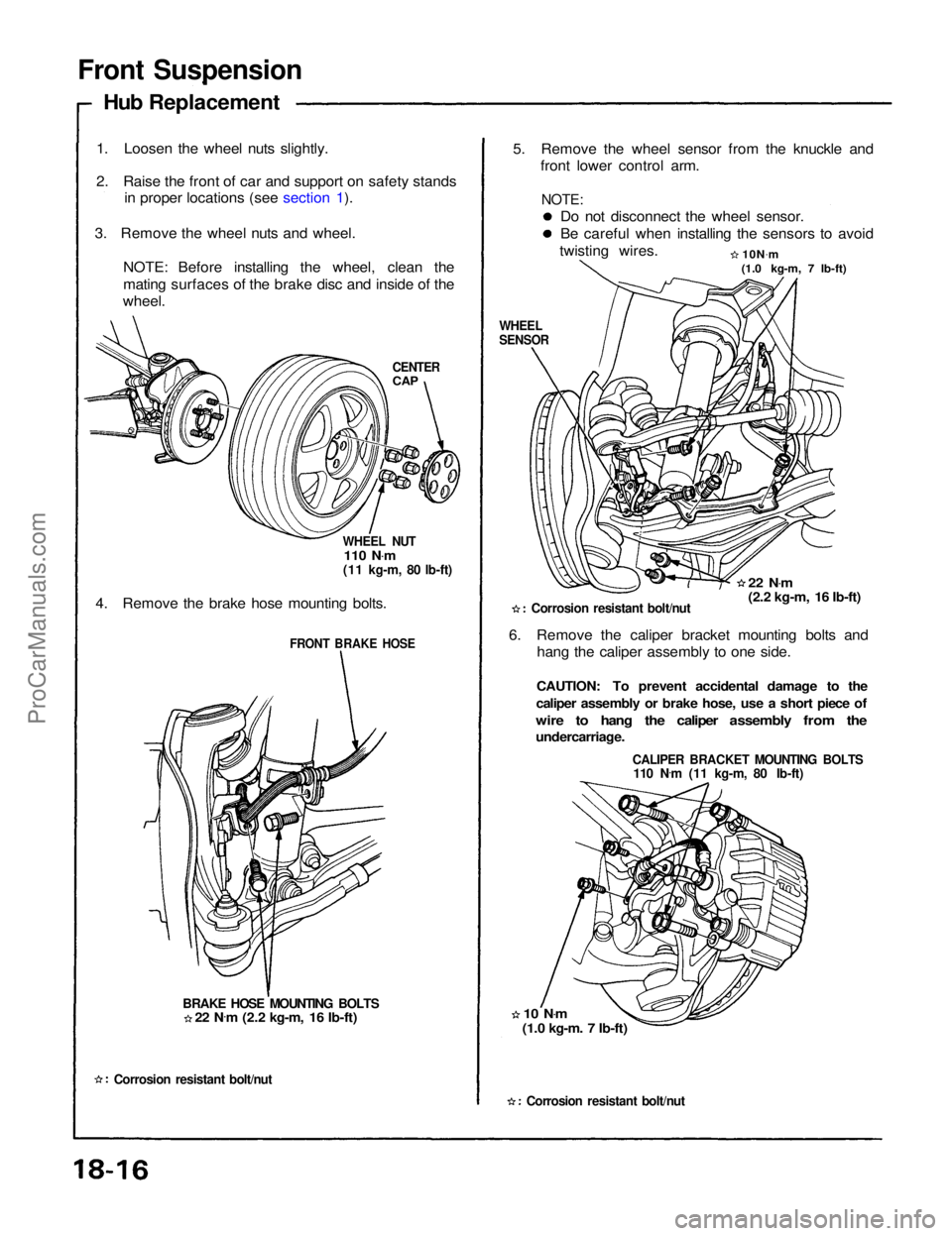
Front Suspension
Hub Replacement
1. Loosen the wheel nuts slightly.
2. Raise the front of car and support on safety stands in proper locations (see section 1).
3. Remove the wheel nuts and wheel. NOTE: Before installing the wheel, clean the
mating surfaces of the brake disc and inside of the
wheel.
CENTER
CAP
WHEEL NUT
110 N .
m
(11 kg-m, 80 lb-ft)
4. Remove the brake hose mounting bolts.
FRONT BRAKE HOSE
BRAKE HOSE MOUNTING BOLTS
Corrosion resistant bolt/nut
5. Remove the wheel sensor from the knuckle and
front lower control arm.
Do not disconnect the wheel sensor.
Be careful when installing the sensors to avoid
twisting wires. 10N.
m
(1.0 kg-m, 7 lb-ft)
WHEEL
SENSOR
22 N.
m
(2.2 kg-m, 16 Ib-ft)
Corrosion resistant bolt/nut
6. Remove the caliper bracket mounting bolts and hang the caliper assembly to one side.
CAUTION: To prevent accidental damage to the
caliper assembly or brake hose, use a short piece of
wire to hang the caliper assembly from the
undercarriage.
CALIPER BRACKET MOUNTING BOLTS
110 N .
m (11 kg-m, 80 Ib-ft)
10 N .
m
(1.0 kg-m. 7 Ib-ft)
Corrosion resistant bolt/nut
22 N
.
m (2.2 kg-m, 16 Ib-ft)
NOTE:ProCarManuals.com
Page 1361 of 1640
Component Location Index
INDICATOR LIGHT
ACTIVATION LIGHT INDICATOR LIGHT
UNDER-HOOD
FUSE/RELAY BOX
ABS
CONTROL UNIT
STEERING
ANGLE SENSOR
(page 19-138)
TCS SWITCH(page 19-137)
UNDER-DASH FUSE BOX
A/T GEAR POSITION
SWITCH
FAIL-SAFE RELAY
(page 19-137)
ENGINE
COMPARTMENT
FUSE/RELAY BOX
TRANSMISSON
CONTROL
MODULE (TCM)
ENGINE
GROUND
TCS CONTROL
UNIT
ENGINE CONTROL
MODULE (ECM)
ACCELERATOR
PEDAL
ANGLE
SENSOR
THROTTLE
ACTUATOR
THROTTLE
POSITION (TP)
SENSORProCarManuals.com
Page 1363 of 1640
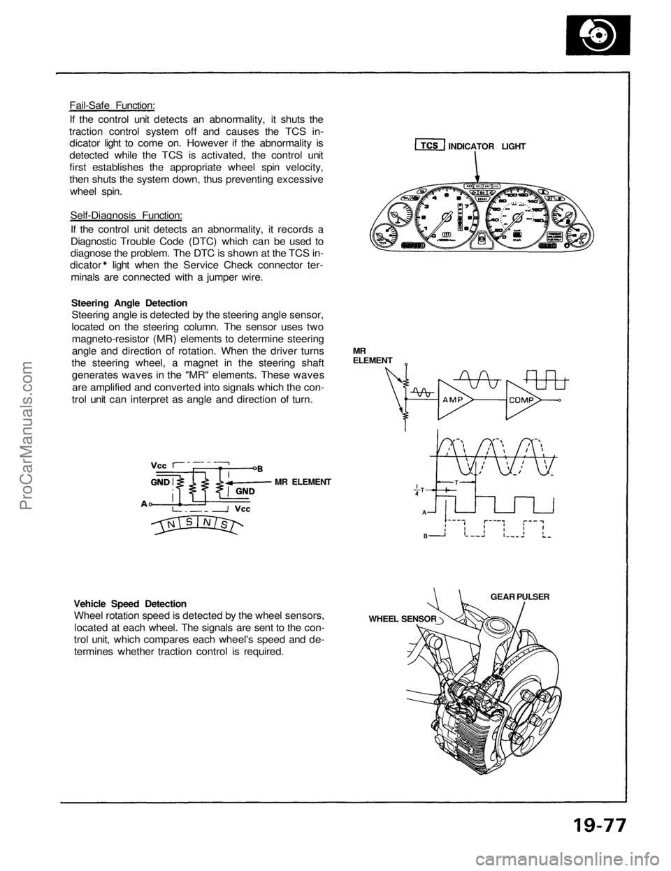
Fail-Safe Function:
If the control unit detects an abnormality, it shuts the
traction control system off and causes the TCS in-
dicator light to come on. However if the abnormality is
detected while the TCS is activated, the control unit
first establishes the appropriate wheel spin velocity,
then shuts the system down, thus preventing excessive
wheel spin.
Self-Diagnosis Function:
If the control unit detects an abnormality, it records a
Diagnostic Trouble Code (DTC) which can be used to
diagnose the problem. The DTC is shown at the TCS in-
dicator light when the Service Check connector ter-
minals are connected with a jumper wire.
Steering Angle Detection
Steering angle is detected by the steering angle sensor,
located on the steering column. The sensor uses two
magneto-resistor (MR) elements to determine steering
angle and direction of rotation. When the driver turns
the steering wheel, a magnet in the steering shaft
generates waves in the "MR" elements. These waves
are amplified and converted into signals which the con-
trol unit can interpret as angle and direction of turn.
Vehicle Speed Detection
Wheel rotation speed is detected by the wheel sensors,
located at each wheel. The signals are sent to the con-
trol unit, which compares each wheel's speed and de-
termines whether traction control is required.
MR ELEMENT
WHEEL SENSOR
GEAR PULSER
MR
ELEMENT
INDICATOR LIGHTProCarManuals.com
Page 1365 of 1640
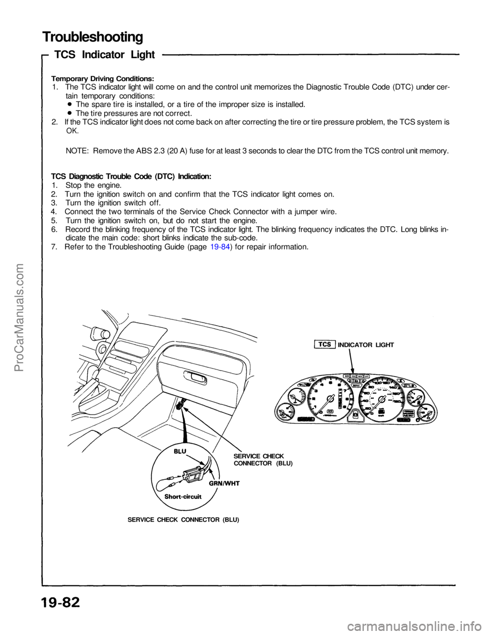
Troubleshooting
TCS Indicator Light
Temporary Driving Conditions:
1. The TCS indicator light will come on and the control unit memorizes the Diagnostic Trouble Code (DTC) under cer-
tain temporary conditions:
2. If the TCS indicator light does not come back on after correcting the tire or tire pressure problem, the TCS system is
OK.
NOTE: Remove the ABS 2.3 (20 A) fuse for at least 3 seconds to clear the DTC from the TCS control unit memory.
TCS Diagnostic Trouble Code (DTC) Indication: 1. Stop the engine.
2. Turn the ignition switch on and confirm that the TCS indicator light comes on.
3. Turn the ignition switch off.
4. Connect the two terminals of the Service Check Connector with a jumper wire.
5. Turn the ignition switch on, but do not start the engine.6. Record the blinking frequency of the TCS indicator light. The blinking frequency indicates the DTC. Long blinks in- dicate the main code: short blinks indicate the sub-code.
7. Refer to the Troubleshooting Guide (page 19-84) for repair information. The spare tire is installed, or a tire of the improper size is installed.
The tire pressures are not correct.
SERVICE CHECK CONNECTOR (BLU)
SERVICE CHECK
CONNECTOR (BLU)
INDICATOR LIGHTProCarManuals.com
Page 1366 of 1640
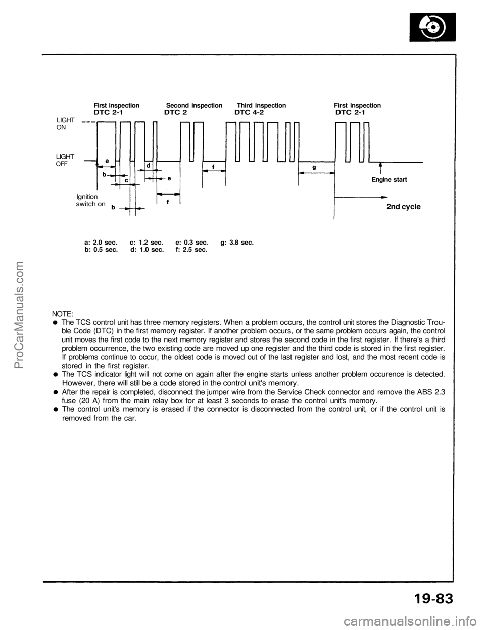
The TCS control unit has three memory registers. When a problem occurs, the control unit stores the Diagnostic Trou-
ble Code (DTC) in the first memory register. If another problem occurs, or the same problem occurs again, the control
unit moves the first code to the next memory register and stores the second code in the first register. If there's a thirdproblem occurrence, the two existing code are moved up one register and the third code is stored in the first register.
If problems continue to occur, the oldest code is moved out of the last register and lost, and the most recent code is
stored in the first register. The TCS indicator light will not come on again after the engine starts unless another problem occurence is detected.
However, there will still be a code stored in the control unit's memory.
After the repair is completed, disconnect the jumper wire from the Service Check connector and remove the ABS 2.3
fuse (20 A) from the main relay box for at least 3 seconds to erase the control unit's memory. The control unit's memory is erased if the connector is disconnected from the control unit, or if the control unit is
removed from the car.
NOTE:
a: 2.0
sec.
c: 1.2
sec.
e: 0.3
sec.
g: 3.8
sec.
b: 0.5
sec.
d: 1.0
sec.
f: 2.5
sec.
Ignition
switch on
LIGHT
ON
LIGHT
OFF
First inspection Second inspection Third inspection First inspection
DTC 2-1 DTC 2 DTC 4-2 DTC 2-1
Engine start2nd cycle
ProCarManuals.com