Page 1324 of 1640
System Description
Electrical Power Steering (EPS)
Outline
The NSX uses an electric motor-driven power steering, which possesses the characteristics best suited for a mid engine
automobile. This system is a power-assisted steering device, with a motor inside the steering gearbox driven by the EPS
control unit and power unit. Its distinctive features are described below:
ALTERNATOR
VEHICLE
SPEED SENSOR
STEERING WHEEL
EPS CONTROL UNIT
POWER UNIT
BATTERY
STEERING GEARBOX
STEERING
COLUMN
Minimized loss of engine horsepower and decreased fuel consumption.
A linear steering feel and the reduction of kickback.
The system is compact and lightweight because it requires no complicated hydraulic piping, etc.ProCarManuals.com
Page 1325 of 1640

FUSE BOX
System Description
Major Components
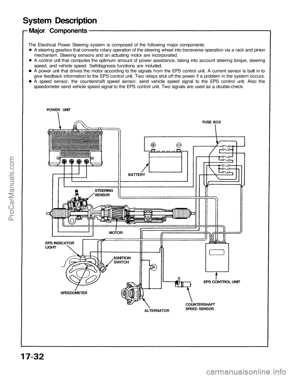
The Electrical Power Steering system is composed of the following major components:
EPS CONTROL UNIT
COUNTERSHAFT
SPEED SENSOR
ALTERNATOR
SPEEDOMETER
EPS INDICATOR
LIGHT
STEERING
SENSOR
BATTERY
POWER UNIT
MOTOR
IGNITION
SWITCH
A steering gearbox that converts rotary operation of the steering wheel into transverse operation via a rack and pinion
mechanism. Steering sensors and an actuating motor are incorporated.
A control unit that computes the optimum amount of power assistance, taking into account steering torque, steering
speed, and vehicle speed. Selfdiagnosis functions are included.
A power unit that drives the motor according to the signals from the EPS control unit. A current sensor is built in to
give feedback information to the EPS control unit. Two relays shut off the power if a problem in the system occurs.
A speed sensor, the countershaft speed sensor, send vehicle speed signal to the EPS control unit. Also the
speedometer send vehicle speed signal to the EPS control unit. Two signals are used as a double-check.ProCarManuals.com
Page 1330 of 1640

Self-Diagnosis Function
The EPS control unit monitors the system inputs and outputs, and the driving current of the motor. If there is a problem
in the system, the control unit turns the system off by actuating the relay in the power unit. Power assist stops and
normal manual steering operation resumes. The control unit also turns the EPS indicator light on to alert the driver, and
memorizes the problem in the form of a code. Connecting the terminals of the service check connector with a jumper
wire enables the EPS indicator light to blink the problem code when the ignition switch is turned on.
Unloader Control
If the steering wheel is turned fully and held in the full-lock position, the steering torque reaches the maximum point,
and an over-current flows to the motor and the power unit. The control unit detects this and reduces the current flow
to the motor.
Average Moving Current Control
The electric current flow to the motor is estimated from the current values detected by the current sensor, and the aver-
age current is obtained at two second intervals. The motor driving current is suppressed when the average current value
exceeds a predetermined marginal value. The control unit regurates the motor current during continuous loading to sup-
press any excessive temperature rise in the power unit and the motor.
Over-Voltage Control
If there is an excessive increase in power source voltage due to a poor battery condition, an alternator voltage regulator
problem, etc., the motor assisting force increases, resulting in excessive control. To prevent this, the control unit signals
to the power unit are corrected to ensure that adequate assisting force is generated.ProCarManuals.com
Page 1333 of 1640
Wiring Locations
EPS CONTROL UNIT
MAIN RELAY BOX
POWER UNIT
TORQUE SENSOR 6-P CONNECTOR/
STEERING WHEEL SPEED SENSOR
4-P CONNECTOR
STEERING GEARBOX
(TORQUE SENSOR/STEERING WHEEL
SPEED SENSOR)
UNDER-DASH FUSE/RELAY BOX
TRANSMISSION CONTROL MODULE (TCM)
22-P CONNECTOR
VEHICLE SPEED SENSOR
(VSS)
ALTERNATOR 4-P CONNECTOR
EPS INDICATOR LIGHTProCarManuals.com
Page 1335 of 1640
Troubleshooting Procedures
Under normal conditions, the EPS indicator light in the gauge assembly comes on when the ignition switch is turned
to the ON position, then goes off after the engine is started. This indicates that the bulb and its circuits are operating
correctly.
EPS INDICATOR LIGHT
When the EPS control unit senses an abnormality in the system, the control unit memorizes the problem, the EPS indica-
tor light blinks at equal intervals, and the power steering assist is turned off.
When the EPS indicator light has been reported on, connect the two terminals of the service check connector with a
jumper wire. Then turn on the ignition switch and observe the blinking frequency.
SERVICE CHECK
CONNECTOR (BLU)
GRN/WHT
SERVICE CHECK CONNECTOR (BLU)
BLUProCarManuals.com
Page 1336 of 1640
Troubleshooting
Diagnostic Trouble Code (DTC) Display
When the service check connector terminals are connected with a jumper wire, the EPS control unit blinks the EPS indi-
cator light to indicate the DTC. The DTC is indicated by a series of long and short blinks. One long blink equals 10 shortblinks. Add the long and short blinks together to determine the DTC, then refer to the Troubleshooting Chart on page 17-51.
Example 1.3 seconds
0.28 seconds
1.3 seconds
0.36 seconds
The control unit can memorize any number of simultaneous problems. The DTC is repeated sequentially beginning with
the lowest number.
The DTC is stored in the control unit memory even when the ignition switch is turned off. After repairing the EPS system,
disconnect the CLOCK fuse in the relay box for more than 10 seconds to reset the EPS control unit memory.ProCarManuals.com
Page 1337 of 1640
Test Harness Installation
Test Harness A
EPS CONTROL UNIT
TEST HARNESS A
07MAZ-SL00100
Test Harness B
TEST HARNESS B
07MAZ-SL00200
STEERING GEARBOX
Test Harness C
POWER UNIT
TEST HARNESS C
07MAZ-SL00300
Power Unit Checker
Connect to the
cigarette lighter
POWER UNIT CHECKER
07MAZ-SL00400
POWER UNIT
OUTPUT
(VIS)
Remove the glove box and disconnect the EPS con-
trol unit connector.
Connect test harness A.
Disconnect the torque sensor and steering speed sen-
sor connectors and connect test harness B. Pull the floor carpet back from the passenger's side
and remove the bass speaker and power unit cover.
Disconnect the connector and connect test harness C.
Pull the floor carpet back from the passenger's side
and remove the bass speaker and power unit cover. Disconnect the connector and connect the power unit
checker.
Remove the cigarette lighter and connect the power
unit checker.ProCarManuals.com
Page 1342 of 1640

Power SteeringGearbox Removal/Installation (cont'd)
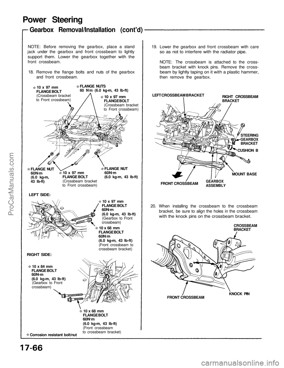
NOTE: Before removing the gearbox, place a stand
jack under the gearbox and front crossbeam to lightly
support them. Lower the gearbox together with the
front crossbeam.
18. Remove the flange bolts and nuts of the gearbox and front crossbeam.
FLANGE NUTS
60 N.m (6.0 kg-m, 43 Ib-ft)
10 x 97 mm
FLANGE BOLT (Crossbeam bracket
to Front crossbeam)
10 x 97 mm
FLANGE BOLT (Crossbeam bracket
to Front crossbeam)
FLANGE NUT
60N .
m
(6.0 kg-m,
43 Ib-ft)
10 x 97 mm
FLANGE BOLT
(Crossbeam bracket
to Front crossbeam)
LEFT SIDE:
RIGHT SIDE:
10 x 84 mm
FLANGE BOLT
60N .
m
(6.0 kg-m, 43 Ib-ft) (Gearbox to Front
crossbeam)
Corrosion resistant bolt/nut
10 x 68 mm
FLANGE BOLT
60N ·
m
(6.0 kg-m, 43 Ib-ft)
(Front crossbeam
to crossbeam bracket)
10 x 68 mm
FLANGE BOLT
60N ·
m
(6.0 kg-m, 43 Ib-ft)
(Front crossbeam to
crossbeam bracket)
10 x 97 mm
FLANGE BOLT
60N·m
(6.0 kg-m, 43 Ib-ft) (Gearbox to Front
crossbeam) 19. Lower the gearbox and front crossbeam with care
so as not to interfere with the radiator pipe.
NOTE: The crossbeam is attached to the cross-
beam bracket with knock pins. Remove the cross-
beam by lightly taping on it with a plastic hammer,
then remove the gearbox.
LEFT CROSSBEAM BRACKET
FRONT CROSSBEAM
GEARBOX
ASSEMBLY
20. When installing the crossbeam to the crossbeam bracket, be sure to align the holes in the crossbeam
with the knock pins on the crossbeam bracket.
CROSSBEAM
BRACKET
KNOCK PIN
FRONT CROSSBEAM RIGHT CROSSBEAM
BRACKET
STEERING
GEARBOX
BRACKET
CUSHION B
MOUNT BASE
FLANGE NUT
60N
·
m
(6.0 kg-m, 43 Ib-ft)ProCarManuals.com