Page 1076 of 1640

Troubleshooting
Troubleshooting Guide
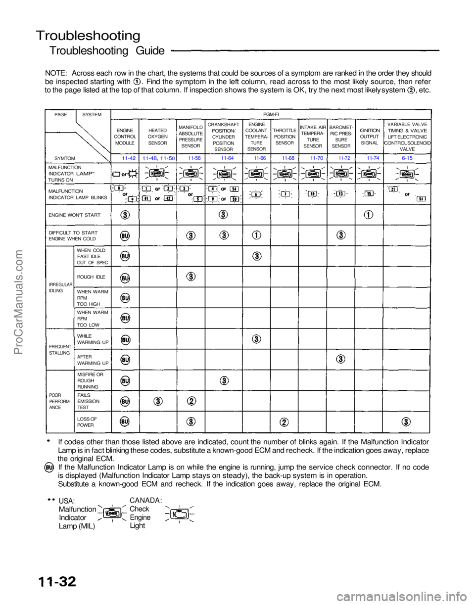
NOTE: Across each row in the chart, the systems that could be sources of a symptom are ranked in the order they should be inspected starting with . Find the symptom in the left column, read across to the most likely source, then refer
to the page listed at the top of that column. If inspection shows the system is OK, try the next most likely system , etc.
If codes other than those listed above are indicated, count the number of blinks again. If the Malfunction Indicator
Lamp is in fact blinking these codes, substitute a known-good ECM and recheck. If the indication goes away, replace
the original ECM.
If the Malfunction Indicator Lamp is on while the engine is running, jump the service check connector. If no code
is displayed (Malfunction Indicator Lamp stays on steady), the back-up system is in operation.
Substitute a known-good ECM and recheck. If the indication goes away, replace the original ECM.
USA:
Malfunction
Indicator
Lamp (MIL)
CANADA:
Check
Engine
Light
PAGE
SYSTEM
SYMTOM
MALFUNCTION INDICATOR
LAMP"
TURNS ON
MALFUNCTION
INDICATOR LAMP BLINKS
ENGINE WON'T START
DIFFICULT TO START
ENGINE WHEN COLD
WHEN COLDFAST IDLE
OUT OF SPEC
IRREGULAR
IDLING
ROUGH IDLE
WHEN WARM
RPM
TOO HIGH
WHEN WARM
RPM
TOO LOW
WHILE
WARMING UP
FREQUENT
STALLING
AFTER
WARMING UP
MISFIRE OR
ROUGH
RUNNING
POOR
PERFORM-
ANCE
FAILS
EMISSION
TEST
LOSS OF
POWER
ENGINE
CONTROL
MODULE
11-42
HEATED
OXYGEN
SENSOR
11-48, 11-50
MANIFOLD
ABSOLUTE
PRESSURE
SENSOR
11-58
CRANKSHAFT
POSITION/
CYLINDER
POSITION
SENSOR
11-64
PGM-FI
ENGINE
COOLANT
TEMPERA-
TURE
SENSOR
THROTTLE
POSITION
SENSOR
INTAKE AIR
TEMPERA-
TURE
SENSOR
BAROMET-
RIC PRES-
SURE
SENSOR
IGNITION
OUTPUT
SIGNAL
VARIABLE VALVE
TIMING & VALVE
LIFT ELECTRONIC
CONTROL SOLENOID
VALVE
6-15
11-74
11-72
11-70
11-68
11-66
ProCarManuals.com
Page 1078 of 1640
Troubleshooting
Self-diagnostic Procedures
I. When the Malfunction Indicator Lamp (MIL) has been reported on, do the following: 1. Connect the Service Check Connector terminals with a jumper wire as shown (the Service Check Connector islocated under the dash on the passenger side of the car). Turn the ignition switch ON.
SERVICE CHECK CONNECTOR (2P)
JUMPER
WIRE
2. Note the Diagnostic Trouble Code (DTC): the MIL indicates a code by the length and number of blinks. The MIL
can indicate any number of simultaneous component problems by blinking separate codes, one after another. Codes
1 through 9 are indicated by individual short blinks. Codes 10 through 59 are indicated by a series of long and
short blinks. The number of long blinks equals the first digit, the number of short blinks equals the second digit.
USA:
MALFUNCTION
INDICATOR
LAMP
(MIL) CANADA:
CHECK
ENGINE
LIGHT
See DTC 1
See DTC 3
See DTC 13
See DTC 1 and 3
See DTC 3 and 4
See DTC 3 and 14ProCarManuals.com
Page 1080 of 1640

Troubleshooting
Self-diagnostic Procedures (cont'd)
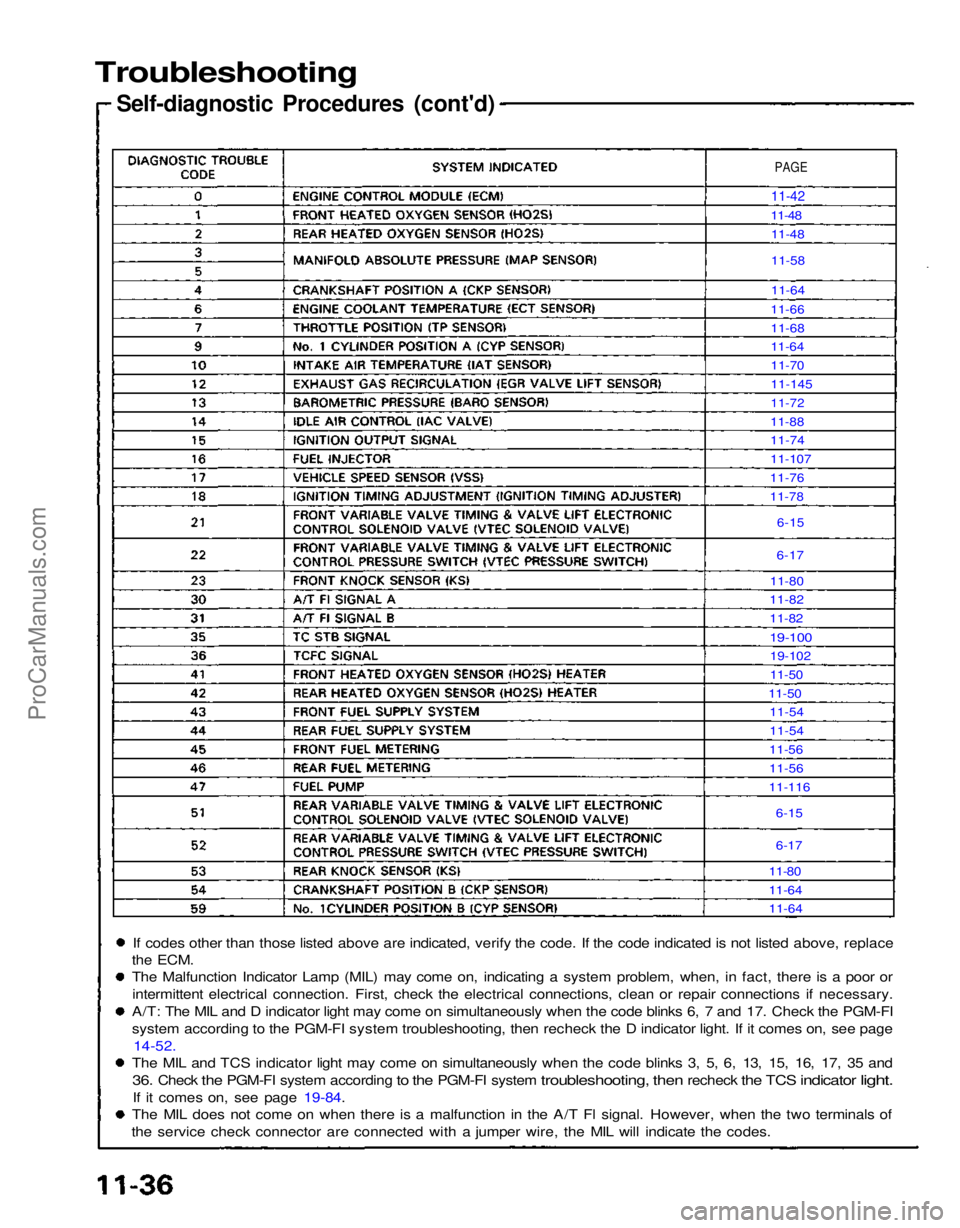
If codes other than those listed above are indicated, verify the code. If the code indicated is not listed above, replace
the
ECM.
The Malfunction Indicator Lamp (MIL) may come on, indicating a system problem, when, in fact, there is a poor or
intermittent electrical connection. First, check the electrical connections, clean or repair connections if necessary.
A/T: The MIL and D indicator light may come on simultaneously when the code blinks 6, 7 and 17. Check the PGM-FI
system according to the PGM-FI system troubleshooting, then recheck the D indicator light. If it comes on, see page 14-52.
The MIL and TCS indicator light may come on simultaneously when the code blinks 3, 5, 6, 13, 15, 16, 17, 35 and
36.
Check
the
PGM-FI system according
to the
PGM-FI system
troubleshooting,
then
recheck
the TCS
indicator
light.
If it comes on, see page 19-84.
The MIL does not come on when there is a malfunction in the A/T Fl signal. However, when the two terminals of
the service check connector are connected with a jumper wire, the MIL will indicate the codes.
PAGE
11-42
11-48 11-48
11-58
11-64
11-66
11-68
11-64
11-70
11-145
11-72
11-88
11-74
11-107
11-76
11-78
6-15
6-17
11-80
11-82
11-82
19-100
19-102
11-50
11-50 11-54
11-54
11-56
11-56
11-116
6-15
6-17
11-80
11-64
11-64ProCarManuals.com
Page 1082 of 1640
Troubleshooting
Self-diagnostic Procedures (cont'd)
CAUTION:
Puncturing the insulation on a wire can cause poor or intermittent electrical connections.
For testing at connectors other than the test harness, bring the tester probe into contact with the terminal from the
connector side of wire harness connectors in the engine compartment. For female connectors, just touch lightly with
the tester probe and do not insert the probe.
TESTER PROBE
TERMINAL
WIRE HARNESS
RUBBER SEALProCarManuals.com
Page 1085 of 1640

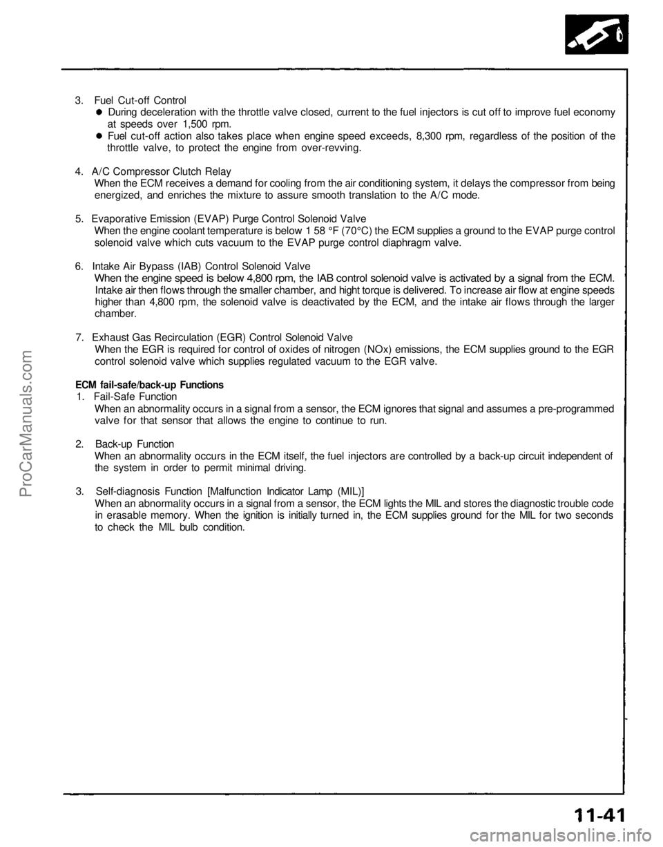
3. Fuel Cut-off Control
During deceleration with the throttle valve closed, current to the fuel injectors is cut off to improve fuel economy
at speeds over 1,500 rpm.
Fuel cut-off action also takes place when engine speed exceeds, 8,300 rpm, regardless of the position of the
throttle valve, to protect the engine from over-revving.
4. A/C Compressor Clutch Relay
When the ECM receives a demand for cooling from the air conditioning system, it delays the compressor from being
energized, and enriches the mixture to assure smooth translation to the A/C mode.
5. Evaporative Emission (EVAP) Purge Control Solenoid Valve
When the engine coolant temperature is below 1 58 °F (70°C) the ECM supplies a ground to the EVAP purge control
solenoid valve which cuts vacuum to the EVAP purge control diaphragm valve.
6. Intake Air Bypass (IAB) Control Solenoid Valve
When the engine speed is below 4,800 rpm, the IAB control solenoid valve is activated by a signal from the ECM.
Intake air then flows through the smaller chamber, and hight torque is delivered. To increase air flow at engine speeds
higher than 4,800 rpm, the solenoid valve is deactivated by the ECM, and the intake air flows through the larger
chamber.
7. Exhaust Gas Recirculation (EGR) Control Solenoid Valve
When the EGR is required for control of oxides of nitrogen (NOx) emissions, the ECM supplies ground to the EGR
control solenoid valve which supplies regulated vacuum to the EGR valve.
ECM fail-safe/back-up Functions
1. Fail-Safe Function
When an abnormality occurs in a signal from a sensor, the ECM ignores that signal and assumes a pre-programmed
valve for that sensor that allows the engine to continue to run.
2. Back-up Function
When an abnormality occurs in the ECM itself, the fuel injectors are controlled by a back-up circuit independent of
the system in order to permit minimal driving.
3. Self-diagnosis Function [Malfunction Indicator Lamp (MIL)]
When an abnormality occurs in a signal from a sensor, the ECM lights the MIL and stores the diagnostic trouble code
in erasable memory. When the ignition is initially turned in, the ECM supplies ground for the MIL for two seconds
to check the MIL bulb condition.ProCarManuals.com
Page 1087 of 1640
Troubleshooting Flowchart
Engine Control Module (ECM)
Malfunction Indicator Lamp (MIL)
never comes on (even for two se-
conds) after ignition is turned on.
Is the low oil pressure light on?
Turn the ignition switch OFF.
Connect the test harness between
the ECM and connectors (see page 11-37).
Connect A13 terminal to body
ground.
Turn the ignition switch ON.
Is the MIL on?
Measure voltage between body
ground and the following termi-
Is there less than 1.0 V?
Substitute a known-good ECM
and recheck. If symptom/indica-
tion goes away, replace the origi-
nal
ECM. Inspect No. 5 (10 A) fuse in the
under-dash fuse box.
Is the fuse OK?
Repair open in YEL wire between
No. 5 (10 A) fuse and gauge as-
sembly.
Replace the MIL bulb.
Repair open in BLU wire be-
tween ECM (A13) and gauge
assembly.
Repair open in wire between ECM
and G101 (located at right middle of engine) that had more than 1.0
V.
Replace the fuse.
G101
(cont'd)
nals individually:
A23,
A24,
A26,
B2.ProCarManuals.com
Page 1089 of 1640

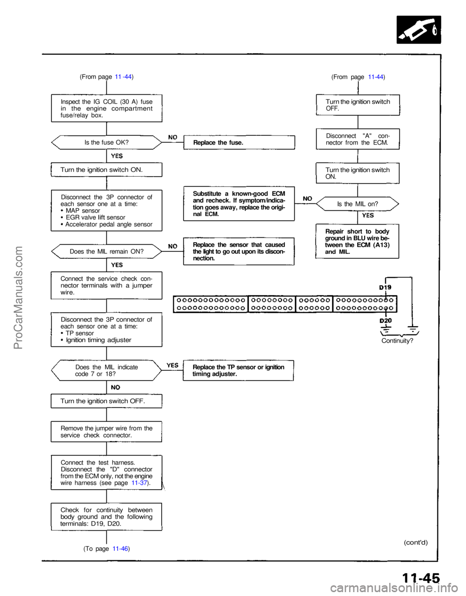
(From page 11 -44)
Inspect the IG COIL (30 A) fuse
in the engine compartment
fuse/relay box.
Is the fuse OK?
Turn the ignition switch ON.
Disconnect the 3P connector of
each sensor one at a time: MAP sensor
EGR
valve
lift
sensor
Accelerator pedal angle sensor
Does the MIL remain ON?
Connect the service check con-
nector terminals with a jumper
wire.
Disconnect the 3P connector of
each sensor one at a time:
TP sensor
Ignition timing adjuster
Does the MIL indicate
code 7 or 18?
Turn the ignition switch OFF.
Remove the jumper wire from the
service check connector.
Connect the test harness.
Disconnect the "D" connector
from the ECM only, not the engine
wire harness (see page 11-37).
Check for continuity between
body ground and the following
terminals: D19, D20.
(To page 11-46) Replace the fuse.
Substitute a known-good ECM
and recheck. If symptom/indica-
tion goes away, replace the origi-
nal
ECM.
Replace the sensor that caused
the light to go out upon its discon- nection.
Replace the TP sensor or ignition
timing adjuster. (From page 11-44)
Turn the ignition switch
OFF.
Disconnect "A" con-
nector from the ECM.
Turn the ignition switch
ON.
Is the MIL on?
Repair short to body
ground in BLU wire be-
tween the ECM (A13)
and
MIL.
Continuity?
(cont'd)ProCarManuals.com
Page 1097 of 1640
Idle Control System
Troubleshooting Flowchart
Alternator (ALT) FR Signal
This signals the ECM when the alternator is charging.
Inspection of ALT FR signal.
Connect the test harness be-
tween the ECM and connector.
Disconnect "D" connector from
the engine wire harness only, not
the ECM (see page 11-37).
Turn the ignition switch ON.
Measure voltage between D9 ( + ) terminal and A26 (-) ter-
minal.
Is there approx. 5 V?
Turn the ignition switch OFF.
Reconnect "D" connector to the
engine wire harness.
Warm up engine to normal oper-ating temperature (the cooling
fan comes on).
Measure voltage between D9( + ) terminal and A26 (-) ter-
minal.
Does the voltage decrease when
headlights and rear defogger are
turned on ?
Do the ECM Reset Procedure
(see page 11-35).
ALT FR signal is OK.(To page 11-93) Substitute a known-good ECM
and recheck. If prescribed
voltage is now available, replace
the original ECM.
Turn the ignition switch OFF.ProCarManuals.com