Page 973 of 1640
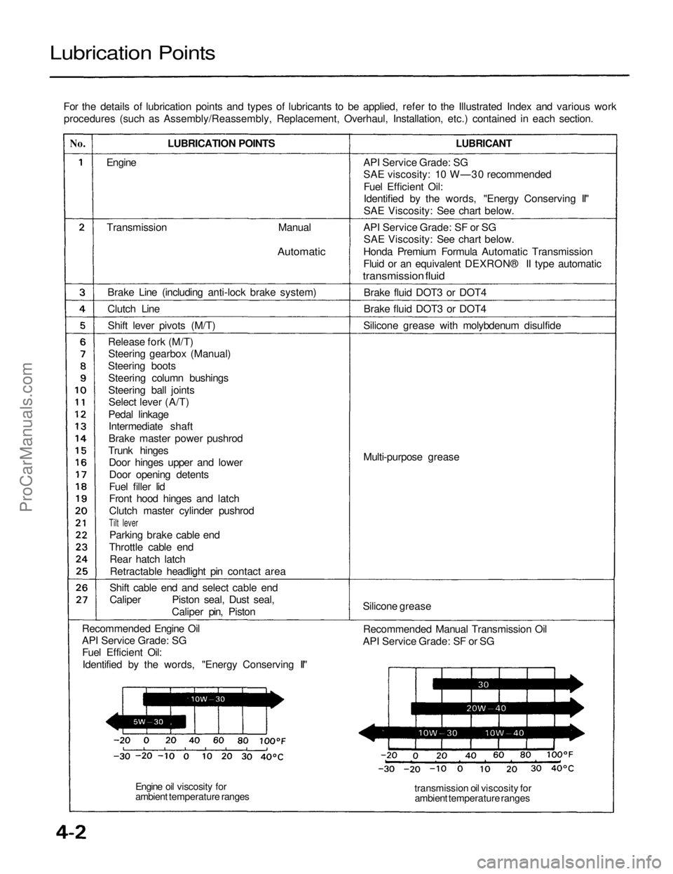
Lubrication Points
For the details of lubrication points and types of lubricants to be applied, refer to the Illustrated Index and various workprocedures (such as Assembly/Reassembly, Replacement, Overhaul, Installation, etc.) contained in each section.
No.
LUBRICATION POINTS
LUBRICANT
Engine
Transmission
Manual
Automatic
Brake Line (including anti-lock brake system)
Clutch Line Shift lever pivots (M/T)Release fork (M/T)Steering gearbox (Manual)
Steering boots Steering column bushings
Steering ball jointsSelect lever (A/T)
Pedal linkage Intermediate shaft
Brake master power pushrod
Trunk hinges Door hinges upper and lower
Door opening detents
Fuel filler lid
Front hood hinges and latch
Clutch master cylinder pushrod
Tilt lever
Parking brake cable end
Throttle cable end Rear hatch latchRetractable headlight pin contact area
Shift cable end and select cable end
Caliper Piston seal, Dust seal, Caliper pin, Piston
Recommended Engine Oil
API Service Grade: SG Fuel Efficient Oil:
Identified by the words, "Energy Conserving II" API Service Grade: SG
SAE viscosity: 10 W—30 recommended
Fuel Efficient Oil:
Identified by the words, "Energy Conserving II"
SAE Viscosity: See chart below.
API Service Grade: SF or SG SAE Viscosity: See chart below.
Honda Premium Formula Automatic Transmission
Fluid or an equivalent DEXRON® II type automatic
transmission fluid
Brake fluid DOT3 or DOT4
Brake fluid DOT3 or DOT4
Silicone grease with molybdenum disulfide
Multi-purpose grease
Silicone grease Recommended Manual Transmission Oil
API Service Grade: SF or SG
transmission oil viscosity forambient temperature ranges
Engine oil viscosity for
ambient temperature rangesProCarManuals.com
Page 978 of 1640
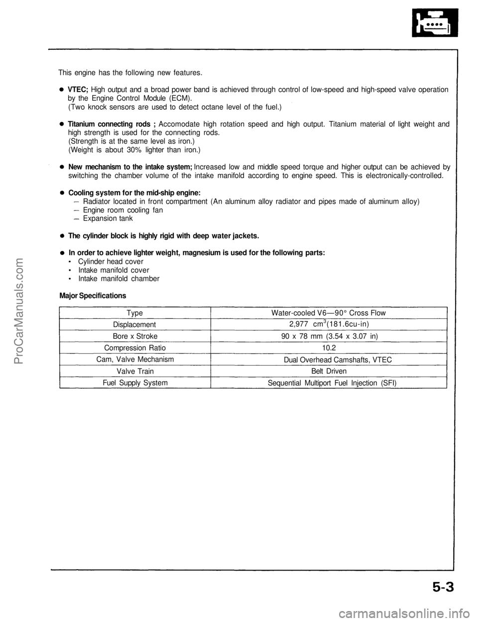
This engine has the following new features.
Type
Displacement
Bore x Stroke
Compression Ratio
Cam, Valve Mechanism
Valve Train
Fuel Supply System Water-cooled V6—90° Cross Flow
2,977 cm3(181.6cu-in)
90 x 78 mm
(3.54
x
3.07
in)
10.2
Dual Overhead Camshafts, VTEC Belt Driven
Sequential Multiport Fuel Injection (SFI)VTEC; High output and a broad power band is achieved through control of low-speed and high-speed valve operation
by the Engine Control Module (ECM).
(Two knock sensors are used to detect octane level of the fuel.)
Titanium connecting rods ; Accomodate high rotation speed and high output. Titanium material of light weight and
high strength is used for the connecting rods.
(Strength is at the same level as iron.)
(Weight is about 30% lighter than iron.)
New mechanism to the intake system; Increased low and middle speed torque and higher output can be achieved by
switching the chamber volume of the intake manifold according to engine speed. This is electronically-controlled.
Cooling system for the mid-ship engine:
Radiator located in front compartment (An aluminum alloy radiator and pipes made of aluminum alloy)
Engine room cooling fan
Expansion tank
The cylinder block is highly rigid with deep water jackets. In order to achieve lighter weight, magnesium is used for the following parts: Cylinder head coverIntake manifold cover
Intake manifold chamber
Major SpecificationsProCarManuals.com
Page 1022 of 1640
Rocker Arms and Lost Motion Assemblies
Inspection
NOTE: When reassembling the primary rocker arm, care-
fully apply air pressure to the oil passage of the rocker
arm.
PRIMARY ROCKER ARM
MID ROCKER ARM
SECONDARY
ROCKER ARM
PISTONS
1. Inspect the rocker arm pistons. Push them
manually.
PRIMARY
MID
SECONDARY
Apply oil to the pistons when reassembling.
Bundle the rocker arms with rubber bands to
keep them together as sets.
LOST MOTION ASSEMBLY
2. Remove the lost motion assembly from the cylinder
head and inspect it. Pushing it gently with the finger
will cause it to sink slightly. Increasing the force on
it will cause it to sink deeper.
Push
NOTE:
Check piston movement
If they do not move smoothly, replace the rocker
arm assembly.
If the lost motion assembly does not move
smoothly, replace it.ProCarManuals.com
Page 1026 of 1640
VALVE SPRING COMPRESSOR
Snap-on CF711
Valves, Valve Springs and Valve Seals
Replacement
NOTE: Identify valves and valve springs as they are re-
moved so that each item can be reinstalled in its original
position.
1. Using an appropriate-sized socket and plastic mallet, lightly tap the valve retainer to loosen the valve keep-
ers before installing the valve spring compressor.
PLASTIC MALLET
SOCKET
2. Install spring compressor. Compress spring and re- move valve keeper.
VALVE SPRING COMPRESSOR
ATTACHMENTEXTENSION
07MAF–PR9010A
VALVE SPRING
COMPRESSOR
ATTACHMENT
07757–PJ1010A
3. Install the special tool as shown.
VALVE SEAL
COMMERCIALLY AVAILABLE
VALVE GUIDE SEAL REMOVER
LISLE P/N 57900 OR KD 3350
SEAL
PULLER
4. Remove the valve guide seal.ProCarManuals.com
Page 1029 of 1640
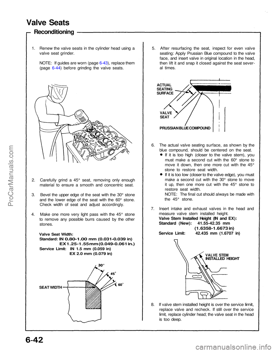
SEAT WIDTH
2. Carefully grind a 45° seat, removing only enough
material to ensure a smooth and concentric seat.
3. Bevel the upper edge of the seat with the 30° stone and the lower edge of the seat with the 60° stone.Check width of seat and adjust accordingly.
4. Make one more very light pass with the 45° stone to remove any possible burrs caused by the otherstones.
Valve Seat Width:
Standard:
IN
0.80-1.00
mm
(0.031-0.039
in)
EX 1.25-1.55 mm (0.049-0.061 in.)
Service Limit: IN 1.5 mm (0.059 in)
EX 2.0 mm (0.079 in)
1. Renew the valve seats in the cylinder head using a
valve seat grinder.
NOTE: If guides are worn (page 6-43), replace them(page 6-44) before grinding the valve seats.
Valve Seats
Reconditioning
5. After resurfacing the seat, inspect for even valveseating: Apply Prussian Blue compound to the valve
face, and insert valve in original location in the head,
then lift it and snap it closed against the seat sever-
al times.
ACTUAL
SEATING
SURFACE
VALVE
SEAT
PRUSSIAN BLUE COMPOUND
7. Insert intake and exhaust valves in the head and measure valve stem installed height.
Valve Stem Installed Height (IN and EX): Standard (New): 41.55-42.35 mm
(1.6358-1.6673 in)
Service Limit: 42.435 mm (1.6707 in)
VALVE STEM
INSTALLED HEIGHT
8. If
valve stem
installed
height
is
over
the
service
limit,
replace valve and recheck. If still over the service
limit, replace cylinder head; the valve seat in the head
is too deep.
6. The actual valve seating surface, as shown by the
blue compound, should be centered on the seat.
If it is too high (closer to the valve stem), you
must make a second cut with the 60° stone to
move it down, then one more cut with the 45°
stone to restore seat width.
If it is too low (closer to the valve edge), you must
make a second cut with the 30° stone to move
it up, then one more cut with the 45° stone to
restore seat width.
NOTE: The final cut should always be made with
the 45° stone.ProCarManuals.com
Page 1035 of 1640
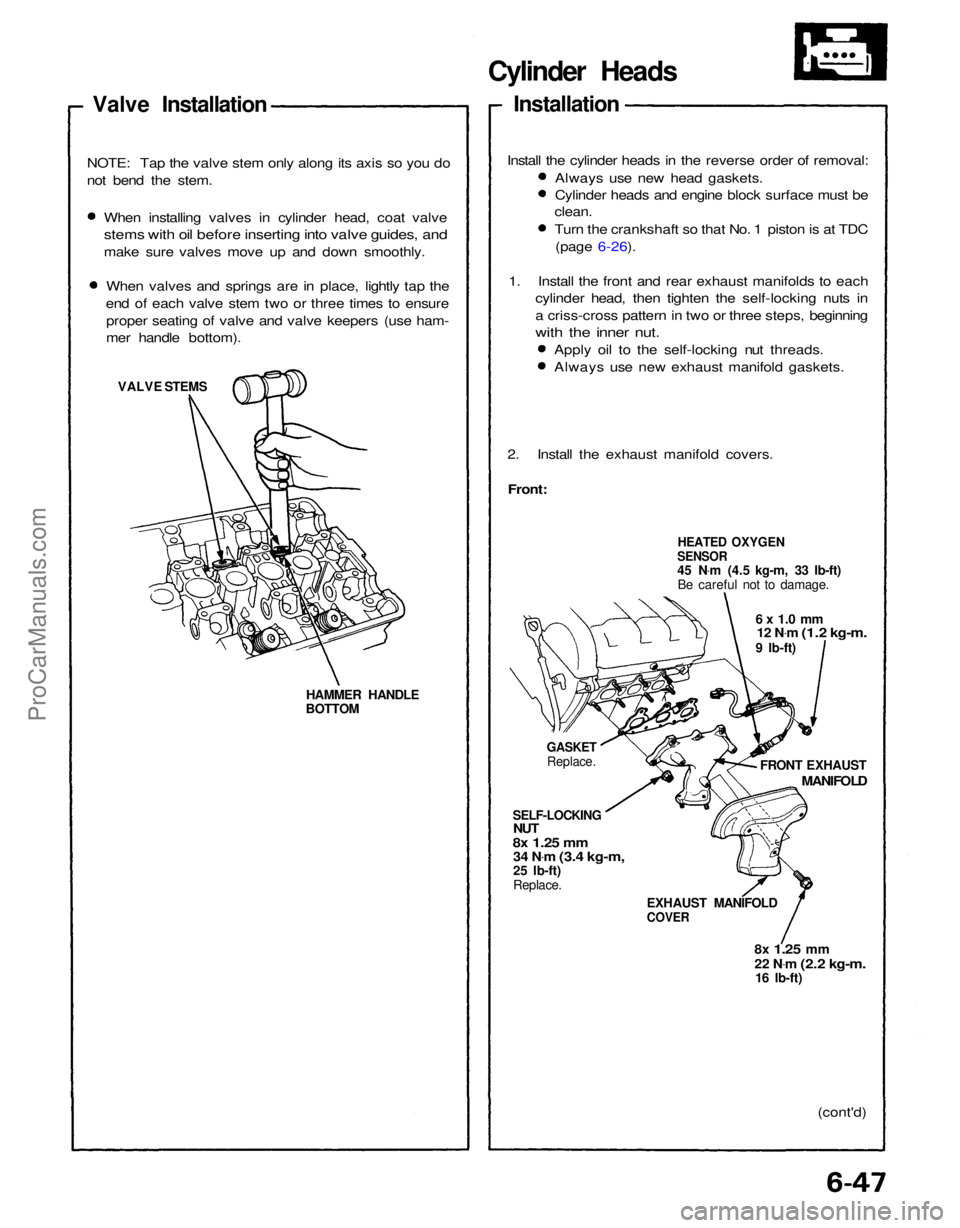
Cylinder Heads
Installation
2. Install the exhaust manifold covers.
Front:
HEATED OXYGEN
SENSOR
45 N .
m (4.5 kg-m, 33 Ib-ft)
Be careful not to damage.
6 x 1.0 mm
12 N .
m
(1.2 kg-m.
9 Ib-ft)
GASKET
Replace.
SELF-LOCKING
NUT
8x
1.25
mm
34 N .
m
(3.4 kg-m,
25 Ib-ft)
Replace.
EXHAUST MANIFOLD
COVER
(cont'd)
8x
1.25
mm
22 N
.
m
(2.2 kg-m.
16 Ib-ft) FRONT EXHAUST
MANIFOLD
Valve Installation
When installing valves in cylinder head, coat valve
stems with oil before inserting into valve guides, and
make sure valves move up and down smoothly.When valves and springs are in place, lightly tap the
end of each valve stem two or three times to ensure proper seating of valve and valve keepers (use ham-
mer handle bottom).
VALVE STEMS
HAMMER HANDLE
BOTTOM
NOTE: Tap the valve stem only along its axis so you do
not bend the stem.
Apply oil to the self-locking nut threads.
Always use new exhaust manifold gaskets.
1. Install the front and rear exhaust manifolds to each
cylinder head, then tighten the self-locking nuts in
a criss-cross pattern in two or three steps, beginning
with the inner nut.
Always use new head gaskets.
Cylinder heads and engine block surface must be
clean.
Turn the crankshaft so that No. 1 piston is at TDC
(page 6-26).
Install the cylinder heads in the reverse order of removal:ProCarManuals.com
Page 1037 of 1640
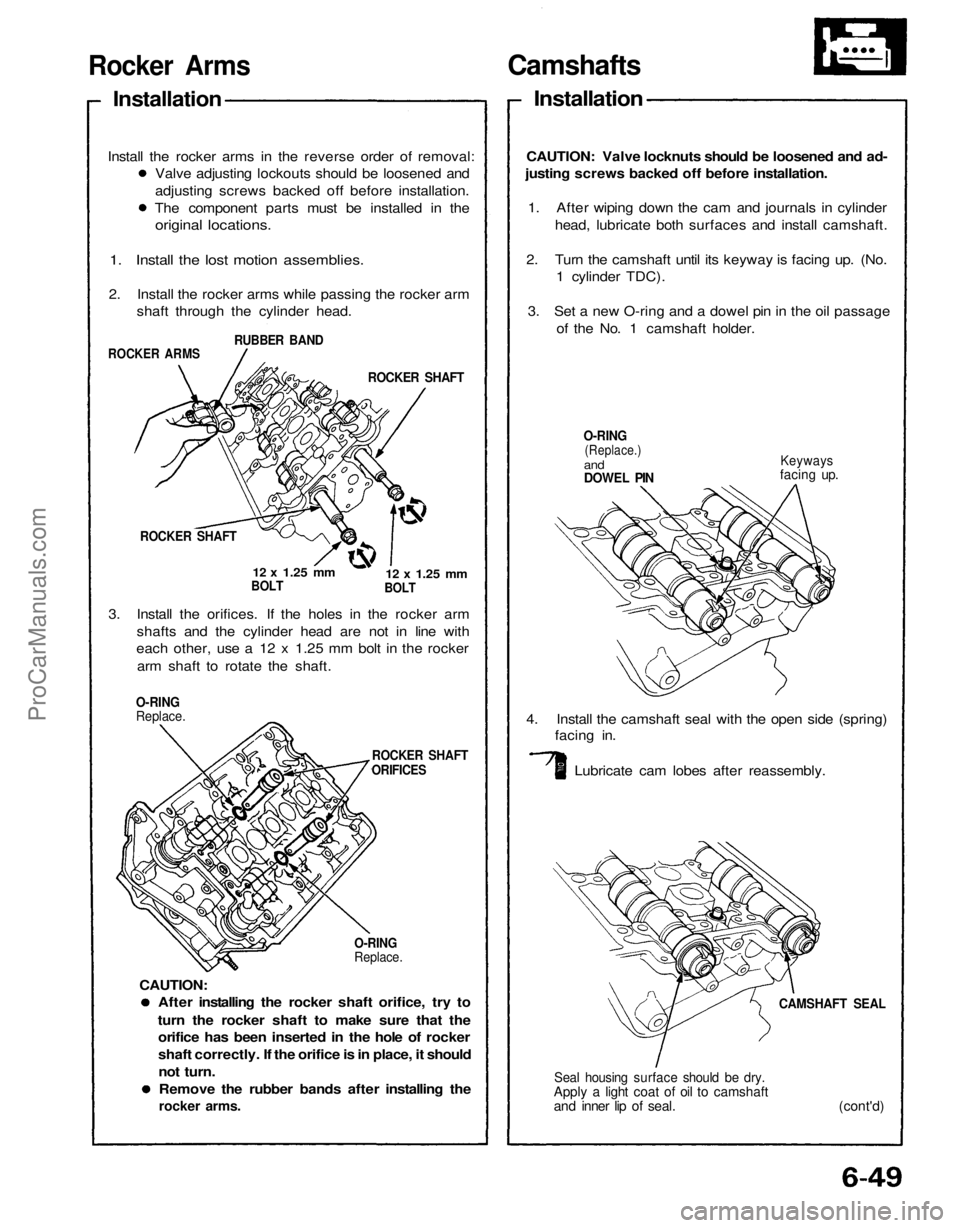
Camshafts
Installation
CAUTION: Valve locknuts should be loosened and ad-
justing screws backed off before installation.
1. After wiping down the cam and journals in cylinder
head, lubricate both surfaces and install camshaft.
2. Turn the camshaft until its keyway is facing up. (No.
1 cylinder TDC).
3. Set a new O-ring and a dowel pin in the oil passage
of the No. 1 camshaft holder.
O-RING
(Replace.)
and
DOWEL PIN
Keyways
facing up.
4. Install the camshaft seal with the open side (spring)
facing in.
Lubricate cam lobes after reassembly.
CAMSHAFT SEAL
Seal housing surface should be dry.
Apply a light coat of oil to camshaft
and inner lip of seal. (cont'd)
After installing the rocker shaft orifice, try to
turn the rocker shaft to make sure that the
orifice has been inserted in the hole of rocker
shaft correctly. If the orifice is in place, it should
not turn.
Remove the rubber bands after installing the
rocker arms.
O-RING
Replace.
ROCKER SHAFT
ORIFICES
O-RING
Replace.
3. Install the orifices. If the holes in the rocker arm
shafts and the cylinder head are not in line with
each other, use a 12 x 1.25 mm bolt in the rocker
arm shaft to rotate the shaft.
ROCKER SHAFT
12 x
1.25
mm
BOLT
12 x
1.25
mm
BOLT
ROCKER SHAFT
ROCKER ARMS
RUBBER BAND
1. Install the lost motion assemblies.
2. Install the rocker arms while passing the rocker arm
shaft through the cylinder head.
Rocker Arms
Installation
Valve adjusting lockouts should be loosened and
adjusting screws backed off before installation.
The component parts must be installed in the
original locations.
Install the rocker arms in the reverse order of removal:
CAUTION:ProCarManuals.com
Page 1042 of 1640
(cont'd)
LOCKNUT
7 x
0.75
mm
20 N
.
m
(2.0 kg-m.
14 Ib-ft)
LOCKNUT
7 x
0.75
mm
20 N .
m
(2.0 kg-m.
14 Ib-ft)
EXHAUST:
6. Tighten locknut and check clearance again. Repeat
adjustment if necessary.
INTAKE:
3. Manually inspect the rocker arms for independent
operation (page 6-52, 53)
4. Adjust valves on No.1 cylinder.
TAPPET ADJUSTER
07MAA–PR70110
TAPPET LOCKNUT
WRENCH
07MAA–PR70120
EXHAUST:
NOTE: Use a mirror to check if the special tool is
positioned on the locknut correctly.
Adjusting screws are on primary and secondary
rocker arms.
Intake: 0.15-0.19 mm (0.006-0.007 in)
Exhaust: 0.17-0.21 mm (0.007-0.008 in)
5. Loosen locknut and turn adjustment screw until feel-
er gauge slides back and forth with slight amount
of drag.
INTAKE:ProCarManuals.com