Page 1211 of 1640
If a customer describes the symptoms for codes 3, 6, 11, 14 or 1 5 yet the indicator light is not blinking, it will
be necessary to recreate the symptom by test driving, and then checking the indicator light with the ignition
still
ON.
If the indicator light displays codes 1,2,3,8, 11, or 16, check first the No. 9, 13 and 18 and fuse before elec-
trical troubleshooting.
If any of the fuses have blown, repair them and then recheck. If the indicator light displays codes other than those listed above or stays lit continuously, the TCM is faulty.
Sometimes the indicator light and the Malfunction Indicator Lamp (MID/Check Engine light may come on
simultaneously. If so, check the PGM-FI system according to the number of blinks on the MIL/Check Engine light,
then reset the memory by removing the CLOCK fuse in the main relay box for more than 10 seconds. Drive the vehicle for several minutes at speed over 30 mph (50 km/h), then recheck the MIL/Check Engine light.PGM-FI system
The PGM-FI system on this model is a sequential multiport fuel injectin system.
The indicator light may comes on, indicating a system problem, when, in fact, there is a poor or intermittent
electrical connection. First, check the electrical connections, clean or repair connections if necessary.If the electrical readings are not as specified when using the test harness, check the test harness connections
before proceeding.
Disconnecting the CLOCK fuse also cancels the radio preset stations and the clock setting. Make note of the radio
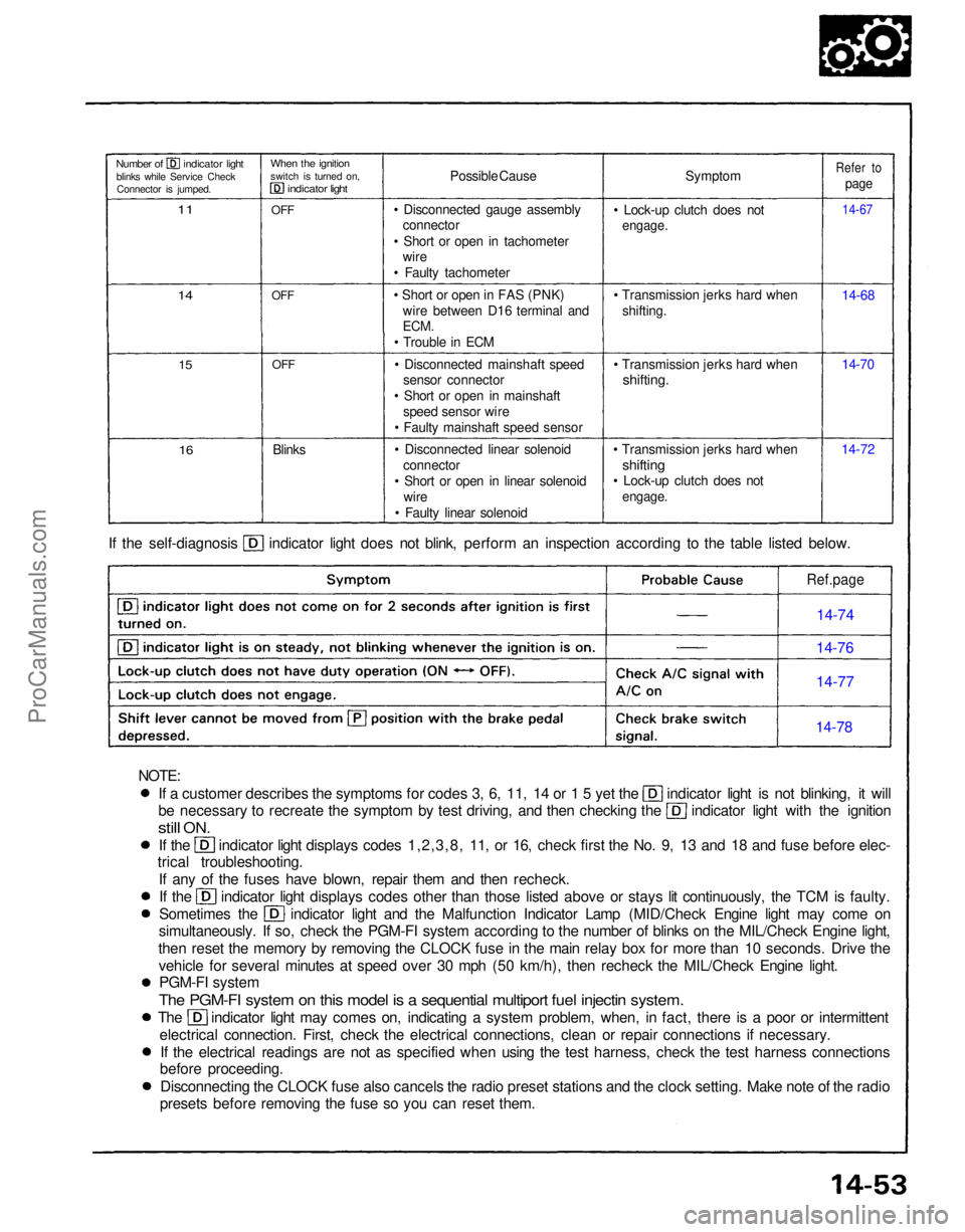
presets before removing the fuse so you can reset them. If the self-diagnosis indicator light does not blink, perform an inspection according to the table listed below.
Symptom
• Lock-up clutch does not
engage.
• Transmission jerks hard when shifting.
• Transmission jerks hard when
shifting.
• Transmission jerks hard when
shifting
• Lock-up clutch does not
engage.
14-7214-70 14-68
14-67
Refer to
page
Possible Cause
• Disconnected gauge assembly connector
• Short or open in tachometer wire
• Faulty tachometer
• Short or open in FAS (PNK) wire between D16 terminal and
ECM.
• Trouble in ECM
• Disconnected mainshaft speed sensor connector
• Short or open in mainshaft speed sensor wire
• Faulty mainshaft speed sensor
• Disconnected linear solenoid connector
• Short or open in linear solenoid wire
• Faulty linear solenoid
Blinks
OFF
OFF
OFF
When the ignition
switch is turned on,
indicator light
Number of indicator light
blinks while Service CheckConnector is jumped.
11
14
15
16
Ref.page
14-74
14-76
14-77
14-78
NOTE:ProCarManuals.com
Page 1242 of 1640
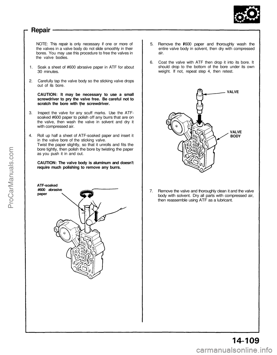
7. Remove the valve and thoroughly clean it and the valve
body with solvent. Dry all parts with compressed air,
then reassemble using ATF as a lubricant.
VALVE
BODY
VALVE
ATF-soaked
#600 abrasive
paper
Repair
NOTE: This repair is only necessary if one or more of
the valves in a valve body do not slide smoothly in their bores. You may use this procedure to free the valves in
the valve bodies.
1. Soak a sheet of #600 abrasive paper in ATF for about
30 minutes.
2. Carefully tap the valve body so the sticking valve drops out of its bore.
CAUTION: It may be necessary to use a small
screwdriver to pry the valve free. Be careful not to scratch the bore with the screwdriver.
3. Inspect the valve for any scuff marks. Use the ATF-
soaked #600 paper to polish off any burrs that are on
the valve, then wash the valve in solvent and dry it
with compressed air.
4. Roll up half a sheet of ATF-soaked paper and insert it in the valve bore of the sticking valve.
Twist the paper slightly, so that it unrolls and fits the
bore tightly, then polish the bore by twisting the paper
as you push it in and out.
CAUTION: The valve body is aluminum and doesn't
require much polishing to remove any burrs.
5. Remove the 600 paper and thoroughly wash the
entire valve body in solvent, then dry with compressed
air.
6. Coat the valve with ATF then drop it into its bore. It should drop to the bottom of the bore under its own
weight. If not, repeat step 4, then retest.ProCarManuals.com
Page 1301 of 1640
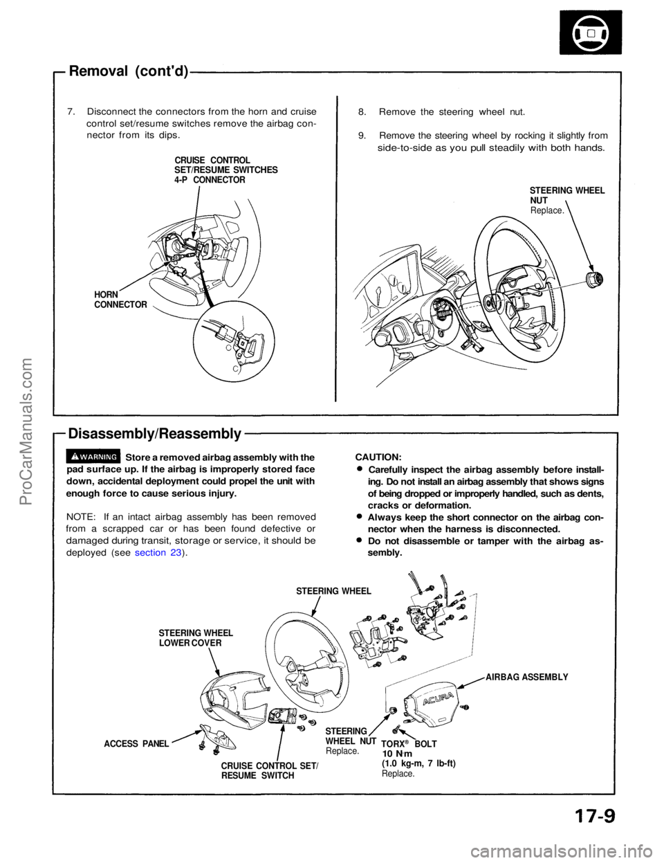
Removal (cont'd)
7. Disconnect the connectors from the horn and cruise control set/resume switches remove the airbag con-nector from its dips.
CRUISE CONTROL
SET/RESUME SWITCHES
4-P CONNECTOR
HORN
CONNECTOR
Disassembly/Reassembly
Store a removed airbag assembly with the
pad surface up. If the airbag is improperly stored face
down, accidental deployment could propel the unit with
enough force to cause serious injury.
NOTE: If an intact airbag assembly has been removed
from a scrapped car or has been found defective or
damaged during transit, storage or service, it should be
deployed (see section 23).
STEERING WHEELLOWER COVER STEERING WHEEL
ACCESS PANEL CRUISE CONTROL SET/RESUME SWITCH STEERING
WHEEL NUT
Replace. TORX
®
BOLT
10 N ·
m
(1.0 kg-m, 7 lb-ft)
Replace. AIRBAG ASSEMBLY
CAUTION:
Carefully inspect the airbag assembly before install-
ing. Do not install an airbag assembly that shows signs
of being dropped or improperly handled, such as dents,
cracks or deformation.
Always keep the short connector on the airbag con- nector when the harness is disconnected.
Do not disassemble or tamper with the airbag as-
sembly.
STEERING WHEEL
NUT
Replace.
8. Remove the steering wheel nut.
9. Remove the steering wheel by rocking it slightly from
side-to-side as you pull steadily with both hands.ProCarManuals.com
Page 1302 of 1640
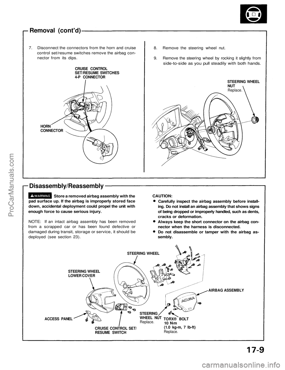
Removal (cont'd)
7. Disconnect the connectors from the horn and cruise control set/resume switches remove the airbag con-nector from its dips.
CRUISE CONTROL
SET/RESUME SWITCHES
4-P CONNECTOR
HORN
CONNECTOR
Disassembly/Reassembly
Store a removed airbag assembly with the
pad surface up. If the airbag is improperly stored face
down, accidental deployment could propel the unit with
enough force to cause serious injury.
NOTE: If an intact airbag assembly has been removed
from a scrapped car or has been found defective or
damaged during transit, storage or service, it should be
deployed (see section 23).
STEERING WHEELLOWER COVER STEERING WHEEL
ACCESS PANEL CRUISE CONTROL SET/RESUME SWITCH STEERING
WHEEL NUT
Replace. TORX® BOLT
10 N .
m
(1.0 kg-m, 7 lb-ft)
Replace. AIRBAG ASSEMBLY
CAUTION:
Carefully inspect the airbag assembly before install-
ing. Do not install an airbag assembly that shows signs
of being dropped or improperly handled, such as dents,
cracks or deformation.
Always keep the short connector on the airbag con- nector when the harness is disconnected.
Do not disassemble or tamper with the airbag as-
sembly.
STEERING WHEEL
NUT
Replace.
8. Remove the steering wheel nut.
9. Remove the steering wheel by rocking it slightly from
side-to-side as you pull steadily with both hands.ProCarManuals.com
Page 1304 of 1640
5.
Install
the
airbag assembly
with
new
TORX
®
bolts.
TORX ®
BOLT
10 N ·
m (1.0 kg-m, 7 Ib-ft)
Replace
TORX ®
BOLTS
10 N ·
m (1.0 kg-m, 7 Ib-ft)
Replace
AIRBAG ASSEMBLY
7. Disconnect the short connector from the airbag 3-P connector.
8. Connect the airbag 3-P connector and cable reel 3-P
connector.
9. Attach the short connector to the access panel, and install the access panel on the steering wheel
lower cover.
ACCESS PANEL SHORT CONNECTOR
(RED)
10. Connect the battery positive terminal and then con-
nect the negative terminal.
11. After installing the airbag assembly, confirm proper system operation:
Turn the ignition to II: the instrument panel SRSindicator light should come on for about 6
seconds and then go off.
Confirm operation of horn buttons.
Confirm operation of cruise control set/resume
switch.
Turn the steering wheel counterclockwise and
make sure the yellow gear tooth still lines up with
the alignment mark.
YELLOW GEAR TOOTH
ALIGNMENT MARKProCarManuals.com
Page 1310 of 1640
12. Install the knee bolster and pad.
13. Connect the foot well light harness and light-on
warning chime to the dashboard lower panel, then
install the dashboard lower panel.
KNEE
BOLSTER
KNEE BOLSTER
PAD
DASHBOARD
LOWER PANEL
14. Install the steering wheel and airbag assembly to the column (see page 17-10).ProCarManuals.com
Page 1317 of 1640
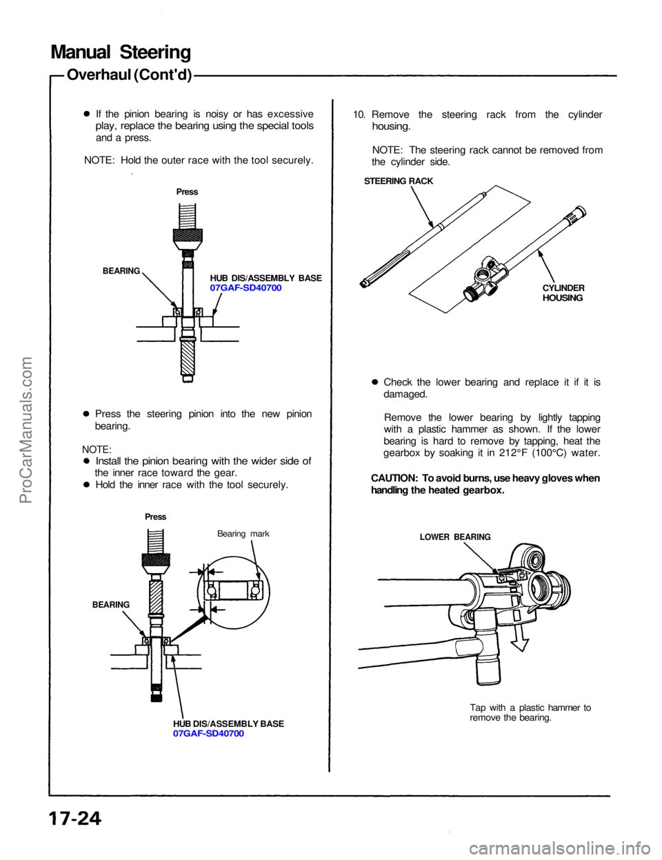
Manual Steering
Overhaul (Cont'd)
If the pinion bearing is noisy or has excessive
play, replace the bearing using the special tools
and a press.
NOTE: Hold the outer race with the tool securely.
Press
HUB DIS/ASSEMBLY BASE
07GAF-SD40700
BEARING
Press the steering pinion into the new pinion
bearing.
NOTE:
Install the pinion bearing with the wider side of
the inner race toward the gear.
Hold the inner race with the tool securely.
Press
Bearing mark
BEARING
HUB DIS/ASSEMBLY BASE
07GAF-SD40700
10. Remove the steering rack from the cylinder
housing.
NOTE: The steering rack cannot be removed from
the cylinder side.
STEERING RACK
CYLINDER
HOUSING
Check the lower bearing and replace it if it is
damaged. Remove the lower bearing by lightly tapping
with a plastic hammer as shown. If the lower
bearing is hard to remove by tapping, heat the
gearbox by soaking it in 212°F (100°C) water.
CAUTION: To avoid burns, use heavy gloves when
handling the heated gearbox.
LOWER BEARING
Tap with a plastic hammer to
remove the bearing.ProCarManuals.com
Page 1322 of 1640
29. Install the new boot bands on the boot and bend both
sets of locking tabs.
30. Lightly tap on the doubled portions to reduce their
height.
NOTE: After assembling, slide the rack right and left
to be certain that the boots are not deformed or
twisted.
31. If the tie-rod ends were removed, install the tie- rods on the right and left rack ends and screw them
in until the threaded section is 11 mm (0.4 in) in
length.
BOOT BAND
11 mm
(0.4
in)
TIE-ROD END
LOCKNUT
Hand tighten.
32. Install the gearbox on the front crossbeam (see page 17-20).
33. Check the wheel alignment and adjust if necessary (see section 18).ProCarManuals.com