Page 1368 of 1640
There should be continuity between the A and B termi-
nals when the battery is connected to the C and D ter-
minals.
There should be no continuity between the A and B ter-
minals when the battery is disconnected.
Fail-Safe Relay Test
Electronic Components
TCS Switch Test
There should be continuity between the D and E termi-
nals when the switch is pushed and there should be no
continuity when the switch is relesed.
Indicator light
Switch
LightProCarManuals.com
Page 1385 of 1640
Dashboard, Door and Floor
DRIVER'S DOOR PANEL
POWER WINDOW
CONTROL UNIT
CIGARETTE LIGHTER
RELAY
SRS UNIT
FOOT WELL BASS SPEAKER RIGHT FRONT FLOOR
PANEL
EPS POWER UNIT
(Behind foot well
bass speaker)
SECURITY CONTROL UNIT
DAYTIME RUNNING
LIGHTS CONTROL
UNIT (Canada)
ABS CONTROL UNIT
CRUISE CONTROL UNIT
EPS CONTROL UNIT
(A/T)
POWER DOOR LOCK
CONTROL UNIT
Wire colors: YEL/RED, BLU/GRN, BRN/YEL, and BLKProCarManuals.com
Page 1386 of 1640
Relay and Control Unit Locations
Rear Bulkhead
FAN CONTROL
UNIT
ECM
TCS FAIL-SAFE
RELAY
Wire colors: YEL,
and LT GRN/BLK TRANSMISSION CONTROL
MODULE (TCM)
DASH LIGHTS
BRIGHTNESS
CONTROL UNIT
TCS CONTROL UNIT
GRN/RED, RED/BLK,ProCarManuals.com
Page 1387 of 1640
RETRACTABLE HEADLIGHT
CONTROL UNIT
INTERLOCK CONTROL
UNIT (A/T)
FUEL PUMP RELAY
Wire colors: YEL, RED,
BLK/YEL, and BLK/REDProCarManuals.com
Page 1393 of 1640

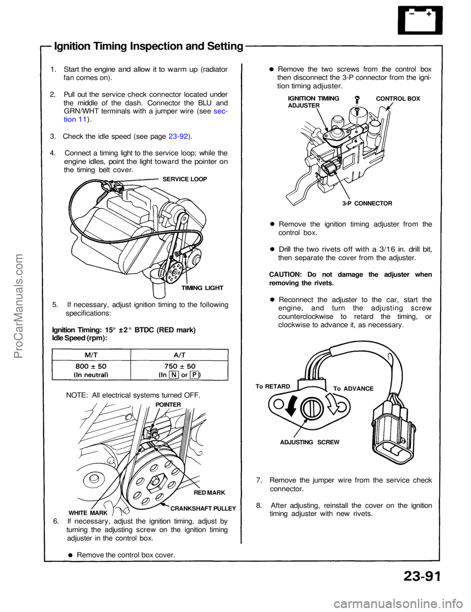
Ignition Timing Inspection and Setting
1. Start the engine and allow it to warm up (radiator
fan comes on).
2. Pull out the service check connector located under the middle of the dash. Connector the BLU andGRN/WHT terminals with a jumper wire (see sec-
tion 11).
3. Check the idle speed (see page 23-92).
4. Connect a timing light to the service loop; while the
engine idles, point the light toward the pointer on
the timing belt cover.
SERVICE LOOP
TIMING LIGHT
5. If necessary, adjust ignition timing to the following specifications:
Ignition Timing: 15° ±2° BTDC (RED mark)
Idle Speed (rpm):
NOTE: All electrical systems turned OFF. POINTER
RED MARK
CRANKSHAFT PULLEY
WHITE MARK
6. If necessary, adjust the ignition timing, adjust by turning the adjusting screw on the ignition timingadjuster in the control box.
Remove the control box cover. 7. Remove the jumper wire from the service check
connector.
8. After adjusting, reinstall the cover on the ignition timing adjuster with new rivets.ADJUSTING SCREW
To ADVANCE
To RETARD Reconnect the adjuster to the car, start the
engine, and turn the adjusting screw
counterclockwise to retard the timing, or
clockwise to advance it, as necessary.
CAUTION: Do not damage the adjuster when
removing the rivets. Remove the ignition timing adjuster from the
control box.
Drill the two rivets off with a 3/16 in. drill bit,
then separate the cover from the adjuster. 3-P CONNECTORCONTROL BOX
IGNITION TIMING
ADJUSTER
Remove the two screws from the control box
then disconnect the 3-P connector from the igni-
tion timing adjuster.ProCarManuals.com
Page 1400 of 1640
Gauge Assembly
Bulb Locations
SRS INDICATOR LIGHT (1.4W)
EPS INDICATOR LIGHT (1.4 W)
RIGHT TURN SIGNAL INDICATOR LIGHT (1.4 W)
BRAKE SYSTEM LIGHT (1.4W)
SEAT BELT REMINDER LIGHT (1.4W)
TCS-OFF INDICATOR
LIGHT (1.96 W)
LOW FUEL INDICATOR
LIGHT (1.4W)
GAUGE LIGHT
(1.4W)
GAUGE LIGHT
(3.0W)
CRUISE LIGHT
(1.96W)
GAUGE LIGHT
(3.0W)
TCS ACTIVATION
INDICATOR LIGHT
(1.96
W)
GAUGE LIGHT
(3.0W)
GAUGE LIGHT
(1.4W)
LOW OIL PRESSURE
INDICATOR
,LIGHT(1.4W)
MALFUNCTION
INDICATOR
LAMP (MIL)
(1.4W)
CHARGING SYSTEM LIGHT (1.4 W)
ABS
INDICATOR LIGHT (1.4 W)
LEFT TURN SIGNAL INDICATOR LIGHT (1.4 W)
TCS INDICATOR LIGHT (1.4W)
HIGH BEAM INDICATOR LIGHT (1.4W)
GAUGE LIGHTS (1.4W x 2)ProCarManuals.com
Page 1404 of 1640
Blown No. 5 (10 A) fuse
(In the under-dash fuse box)
Blown No. 34 (15 A) fuse
(In the under-dash fuse box)
Safety indicator input
Safety indicator (Diodes)Brake light failure sensorDoor switch
Trunk latch switch
Retractable headlight control unit
(see page 23-174)
Poor ground
Open circuit, loose or disconnected
terminalsProCarManuals.com
Page 1405 of 1640
A/T Gear Position Indicator
CAUTION:
• All SRS wiring harnesses are covered with yellow out-
er insulation.
• Before disconnecting any part of the SRS wire har-
ness, install the short connectors (see page 24-10 ('93-'96))
• Replace the entire affected SRS harness assembly if it has an open circuit or damaged wiring.
• After installing the gauge assembly, recheck the oper-
ation of the SRS Indicator light.
CONNECTOR "A" (Carrios the SRS Indicator signal)
SRS MAIN
HARNESS
A/T GEAR POSITION
INDICATOR
Input Test, page 23-154 ('91-'93)
TRANSMISSION
CONTROL MODULE (TCM)
See Automatic transmission
section 14
AfT GEAR POSITION
SWITCH
Test, page 23-160
Replacement, page 23-161
Component Location IndexProCarManuals.com