Page 1431 of 1640
Rear Window Defogger
Switch Light Bulb Replacement
1. Remove the steering column lower and upper covers.
2. Remove the four screws from the combination
switch.
3. Remove the rear window defogger switch (see previous page).
4. Remove the rear window defogger switch bulbs.
BULBS (0.91 W)
REAR WINDOW
DEFOGGER SWITCH Relay Test
1. Remove the defogger relay in the engine compart- ment fuse/relay box.
2. There should be continuity between the C and D terminals.
3. There should be continuity between the A and B terminals when power and ground are connected to
the C and D terminals.
There should be no continuity when power isdisconnected.ProCarManuals.com
Page 1437 of 1640
Cruise Control
Component Location Index
CAUTION:
All SRS wiring harnesses are covered with yellow
outer Insulation.
Before disconnecting any part of the SRS wire
hamess Install the short connectors (see page
24-10).
Replace the entire affected SRS harness assembly if
it has an open circuit or damaged wiring.
BRAKE SWITCH
Test, page 23-308 MAIN SWITCH
Test, page 23-299 Replacement, page 23-298
INDICATOR LIGHT and
DIMMING CIRCUIT
(In the gauge assembly)
Bulb Locations, page 23-128
CLUTCH SWITCH (M/T)
Teat, page 23-308
CABLE REEL
Test, page 23-250
Replacement
,
page 23-344
A/T GEAR POSITION
SWITCH
Test, 23-309
Replacement, page 23-161
CRUISE CONTROL UNIT
Inpu
t
Test, page 23-296
SRS
MAIN
HARNESS
SET/RESUME SWITCH
Test
,
page 23-307Replacement
,
page 23-307
ProCarManuals.com
Page 1439 of 1640

Cruise Control
Description
The cruise control system uses mechanically and elec-
trically operated devices to maintain vehicle speed at a
setting selected by the driver.
The cruise control unit receives command signals from
the cruise control main switch and the cruise control
set/resume switch. It receives information about
operating conditions from the brake switch, ECM, vehi-
cle speed sensor (VSS), the clutch switch (with manual
transmission), or the A/T gear position switch (with
automatic transmission). The cruise control unit sends
operational signals to the devices that regulate the
throttle position. The throttle position maintains the
selected vehicle speed. Essentially, the control unit
compares the actual speed of the vehicle to the
selected speed. Then, the control unit uses the result of
that comparison to open or close the throttle.
The brake switch releases the system's control of the
throttle at the instant the driver depresses the brake
pedal. The switch sends an electronic signal to the con-
trol unit when the brake pedal is depressed; the control
unit responds by allowing the throttle to close. The
clutch switch (manual transmission) or the A/T gear
position switch (automatic transmission) sends a
disengage signal to the control unit that also allows the
throttle to close.
Operation:
The cruise control system will set and automatically
maintain any speed above 30 mph (45 kph). To set,
make sure that the main switch is in the "ON" position.
After reaching the desired speed, press the set switch.
The cruise control unit will receive a set signal and, in
turn, will actuate the cruise control actuator. When the
set switch is depressed and the cruise control system is
on, the "cruise control" ON indicator in the gauge
assembly will light up. You can cancel the cruise control
system by pushing the main switch to "OFF". This
removes power to the control unit and erases the set
speed from memory. If the system is disengaged tem-
porarily by the brake switch, clutch switch, or A/T gear
position switch and vehicle speed is still above 30 mph,
press the resume switch. With the resume switch
depressed and the set memory retained, the vehicle
automatically returns to the previous set speed.
For gradual acceleration without depressing the ac-
celerator pedal, push the resume switch down and hold
it there until the desired speed is reached. This will send
an acceleration signal to the control unit. When the
switch is released, the system will be reprogrammed for
the new speed. To slow down, depress the set switch.
This will send a deceleration signal to the control unit
causing the car to coast until the desired speed is reach-
ed. When the desired speed is reached, release the set
switch. This will reprogram the system for the new
speed.ProCarManuals.com
Page 1445 of 1640
5. Remove the four screws and remove the combina-
tion light switch (main switch).
COMBINATION LIGHT SWITCH
10-P CONNECTOR
16-P CONNECTOR
Main Switch Test
1. Remove the dashboard lower panel and knee bolster pad.
2. If necessary, remove the knee bolster.
3. Disconnect the 16-P connector and check for con- tinuity between the terminals in each switch posi-
tion according to the table.
CRUISE
MAIN
SWITCH
16-P CONNECTOR
View from terminal sideProCarManuals.com
Page 1446 of 1640
5. Remove the four screws and remove the combina-
tion light switch (main switch).
COMBINATION LIGHT SWITCH
10-P CONNECTOR
16-P CONNECTOR
Main Switch Test
1. Remove the dashboard lower panel and knee
bolster pad.
2. If necessary, remove the knee bolster.
3. Disconnect the 16-P connector and check for con-
tinuity between the terminals in each switch posi-
tion according to the table.
CRUISE
MAIN
SWITCH
16-P CONNECTOR
View from terminal sideProCarManuals.com
Page 1456 of 1640
Label Locations
SRS CAUTION LABELS: Refer to page 1-6.
BATTERY CAUTION ALB CAUTION
ALB and BRAKE
FLUID CAUTION
COOLING FAN
CAUTION
RADIATOR BLEED
PLUG CAUTION
AIR CONDITIONER
CAUTION
RETRACTABLE
HEADLIGHT CAUTION
FAN CAUTION
EXPANSION
TANK CAP
CAUTION
COOLANT
CAUTION PRECAUTION
EMISSION CONTROL
INFORMATION and
VACUUM HOSE
ROUTING DIAGRAM
SPARK PLUG
CAUTION
TIRE INFORMATIONProCarManuals.com
Page 1458 of 1640

E: MODULE WARNING
J: STEERING WHEEL WARNING
WARNING
TO PREVENT ACCIDENTAL DEPLOYMENT AND POSSIBLE
INJURY:
ALWAYS INSTALL THE PROTECTIVE SHORT CONNEC-
TOR ON THE INFLATOR CONNECTOR WHEN THE
HARNESS IS DISCONNECTED.
UNDER NO CIRCUMSTANCES SHOULD DIAGNOSIS BE
PERFORMED USING ELECTRICAL TEST EQUIPMENT OR
PROBING DEVICES.
NO SERVICEABLE PARTS INSIDE. DO NOT DISASSEMBLE
OR TAMPER.
STORE THE REMOVED AIRBAG ASSEMBLY WITH THE
PAD SURFACE UP.
FOR SPECIAL HANDLING OR STORAGE REFER TO THE
ACURA SERVICE MANUAL.
DISPOSE OF THE ENTIRE UNIT AS DIRECTED.
F: DRIVER INFORMATION
ALWAYS WEAR YOUR SEAT BELT
THIS CAR IS EQUIPPED WITH A DRIVER AIRBAG AS A
SUPPLEMENTAL RESTRAINT SYSTEM (SRS)
IT IS DESIGNED TO SUPPLEMENT THE SEAT BELT.
BEFORE DRIVING READ LABEL INSIDE THE GLOVE
BOX.
K: LABEL
WARNING
TO PREVENT ACCIDENTAL DEPLOYMENT AND POSSIBLE
INJURY:
ALWAYS INSTALL THE PROTECTIVE SHORT CONNEC-
TOR ON THE INFLATOR CONNECTOR WHEN THE
HARNESS IS DISCONNECTED.
L: INFLATOR LABEL
DANGER CONTAINS SODIUM AZIDE AND POTASSIUM
NITRATE.
CONTENTS ARE EXTREMELY FLAMMABLE.
DO NOT DISMANTLE OR INCINERATE.
DO NOT PROBE WITH ELECTRICAL DEVICES.
M: INFLATOR COVER LABEL
DANGER
EXPLOSIVE/FLAMMABLE
CONTACT WITH ACID, WATER, OR HEAVYMETALS
SUCH AS COPPER, LEAD, OR MERCURY, MAY PRODUCE
HARMFUL AND IRRITATING GASES OR EXPLOSIVE COM-
POUNDS. STORAGE TEMPERATURES MUST NOT EX-
CEED 200°F. FOR PROPER HANDLING, STORAGE, AND
DISPOSAL PROCEDURES REFER TO THE ACURA SERVICE
MANUAL, SRS SUPPLEMENT.
POISON
CONTAINS POISONOUS SODIUM AZIDE AND
POTASSIUM NITRATE.
FIRST AID:
IF CONTENTS ARE SWALLOWED, INDUCE VOMITING.
FOR EYE CONTACT, FLUSH EYES WITH WATER FOR 15
MINUTES. IF GASES (FROM ACID OR WATER CONTACT)
AIR INHALED, SEEK FRESH AIR. IN EVERY CASE, GET
PROMPT MEDICAL ATTENTION.
KEEP OUT OF REACH OF CHILDREN.
G: SRS UNIT CAUTION
CAUTION
NO SERVICEABLE PARTS INSIDE.
DO NOT DISASSEMBLE OR TAMPER.
DO NOT DROP.
STORE IN A CLEAN, DRY AREA.
H: STEERING COLUMN CAUTION
CAUTION
I: POCKET INFORMATION
TO AVOID DAMAGING THE SRS CABLE OR REEL, WHICH
COULD MAKE THE SYSTEM INOPERATIVE. REMOVE THE
STEERING WHEEL BEFORE REMOVING THE STEERING
SHAFT CONNECTOR BOLT.
DRIVER'S AIRBAG INFORMATION
SUPPLEMENTAL RESTRAINT SYSTEM (SRS) CAN
PROVIDE ADDITIONAL PROTECTION FOR THE DRIVER
IN A FRONTAL COLLISION. A FUNCTIONAL
DESCRIPTION OF THE SRS IS IN YOUR OWNER'S
MANUAL.
THE SYSTEM MUST BE INSPECTED TEN YEARS AFTER
DATE OF MANUFACTURE, AS NOTED ON THE
CERTIFICATION PLATE.
ANY REPAIR, INSPECTION OR NEARBY ACCESSORY
INSTALLTION SHOULD BE DONE BY AN ACURA
DEALER.
IF YOUR SRS INDICATOR:
LIGHTS WHILE DRIVING OR FLASHES;
FAILS TO LIGHT OR STAYS ON AFTER THE IGNITION
IS FIRST TURNED ON:
SEE YOUR AUTHORIZED ACURA DEALER.ProCarManuals.com
Page 1477 of 1640

Troubleshooting
Troubleshooting Guide
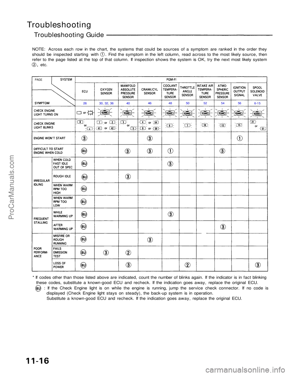
NOTE: Across each row in the chart, the systems that could be sources of a symptom are ranked in the order they should be inspected starting with . Find the symptom in the left column, read across to the most likely source, then
refer to the page listed at the top of that column. If inspection shows the system is OK, try the next most likely system
,
etc.
* If codes other than those listed above are indicated, count the number of blinks again. If the indicator is in fact blinking these codes, substitute a known-good ECU and recheck. If the indication goes away, replace the original ECU. : If the Check Engine light is on while the engine is running, jump the service check connector. If no code is
displayed (Check Engine light stays on steady), the back-up system is in operation.
Substitute a known-good ECU and recheck. If the indication goes away, replace the original ECU.
PAGE
26
30, 32, 36
40
46
48
50
52
54
56
6-15ProCarManuals.com