Page 1498 of 1640

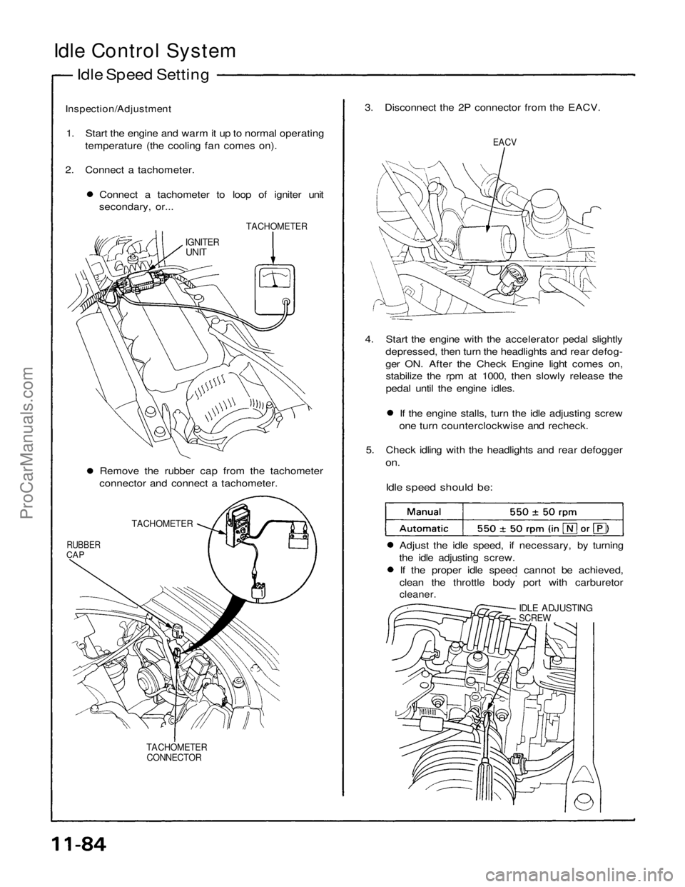
Idle Control System
Idle Speed Setting
Inspection/Adjustment
1. Start the engine and warm it up to normal operating temperature (the cooling fan comes on).
2. Connect a tachometer. Connect a tachometer to loop of igniter unit
secondary, or... 3. Disconnect the 2P connector from the EACV.
EACV
TACHOMETER
IGNITER
UNIT
4. Start the engine with the accelerator pedal slightlydepressed, then turn the headlights and rear defog-
ger ON. After the Check Engine light comes on,stabilize the rpm at 1000, then slowly release the
pedal until the engine idles. If the engine stalls, turn the idle adjusting screw
one turn counterclockwise and recheck.
5. Check idling with the headlights and rear defogger
on.
Idle speed should be:
Remove the rubber cap from the tachometer
connector and connect a tachometer.
TACHOMETER
RUBBER
CAP
Adjust the idle speed, if necessary, by turning
the idle adjusting screw. If the proper idle speed cannot be achieved,
clean the throttle body port with carburetor
cleaner.
IDLE ADJUSTING
SCREW
TACHOMETER CONNECTORProCarManuals.com
Page 1499 of 1640
6. Turn the ignition switch OFF.
7. Reconnect the 2P connector on the EACV, then
remove CLOCK fuse in the under-hood fuse/relay
box for 10 seconds to reset ECU.
8. Restart and idle the engine with no-load conditions
in which the headlights, blower fan, rear defogger,
cooling fan, and air conditioner are not operating
for one minute, then check the idle speed.
Idle speed should be:ProCarManuals.com
Page 1506 of 1640
Fuel Supply System
Pressure Regulator (cont'd)
3. Check that the fuel pressure rises when the vacuum hose from the regulator is disconnected again.
If the fuel pressure did not rise, check to see if it
rises with the fuel return hose lightly pinched.
If the fuel pressure still does not rise, replace the
pressure regulator.
Replacement
Do not smoke while working on fuel sys-
tem . Keep open flame away from work area.
1. Place a shop towel under pressure regulator, then
relieve fuel pressure (page
11-87).
2. Disconnect the vacuum hose and fuel return hose.
3. Remove the two 6 mm retainer bolts.
O-RING
Replace.
PRESSURE REGULATOR
RETURN HOSE
SHOP TOWEL
NOTE:
Replace the O-ring. When assembling the regulator, apply clean engine
oil to the O-ring and assemble it into its proper
position, taking care not to damage the O-ring.ProCarManuals.com
Page 1520 of 1640

Air Intake System
Throttle Body
Description
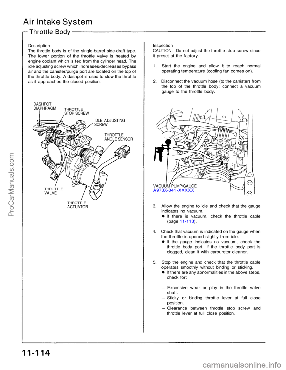
The throttle body is of the single-barrel side-draft type.
The lower portion of the throttle valve is heated by
engine coolant which is fed from the cylinder head. Theidle adjusting screw which increases/decreases bypass
air and the canister/purge port are located on the top of
the throttle body. A dashpot is used to slow the throttle as it approaches the closed position.
Inspection
CAUTION: Do not adjust the throttle stop screw since
it preset at the factory.
1. Start the engine and allow it to reach normal operating temperature (cooling fan comes on).
2. Disconnect the vacuum hose (to the canister) from the top of the throttle body; connect a vacuum
gauge to the throttle body.
DASHPOT
DIAPHRAGM
THROTTLE
STOP SCREW
IDLE ADJUSTING
SCREW
THROTTLE
ANGLE SENSOR
VACUUM PUMP/GAUGE
A973X-041 -XXXXX
THROTTLE
VALVE
THROTTLE
ACTUATOR
3. Allow the engine to idle and check that the gauge
indicates no vacuum. If there is vacuum, check the throttle cable
(page 11-113).
4. Check that vacuum is indicated on the gauge when
the throttle is opened slightly from idle.
If the gauge indicates no vacuum, check the
throttle body port. If the throttle body port is clogged, clean it with carburetor cleaner.
5. Stop the engine and check that the throttle cable operates smoothly without binding or sticking. If there are any abnormalities in the above steps,
check for:
Excessive wear or play in the throttle valve
shaft.
Sticky or binding throttle lever at full close
position.
Clearance between throttle stop screw and
throttle lever at full close position.ProCarManuals.com
Page 1528 of 1640
System Description
Tailpipe Emission
The emission control system includes a three-way catalytic converter, exhaust gas recirculation (EGR) system,
crankcase ventilation system and evaporative control
system.
The emission control system is designed to meet federal and
state emission standards.
Inspection
Do not smoke during this procedure. Keep
any open flame away from your work area.
1. Starting the engine and warm it up to normal operating temperature by driving the car on theroad.
2. Connect a tachometer.
3. Check idle speed and adjust the idle speed, if necessary (page 11-84).
4. Warm up and calibrate the CO meter according to the meter manufacturer's instructions.
5. Check idle CO with the headlights, heater blower, rear window defogger, cooling fan, and air conditioner off.
CO meter should indicate 0.1 % maximum.ProCarManuals.com
Page 1531 of 1640
Emission Control System
Positive Crankcase Ventilation System
Description The Positive Crankcase Ventilation (PCV) system is
designed to prevent blow-by gas from escaping to theatmosphere. The PCV valve contains a spring-loaded
plunger. When the engine starts, the plunger in the PCV
valve is lifted in proportion to intake manifold vacuum and
the blow-by gas is drawn directly into the intake manifold.
PCV HOSE
BLOW-BY VAPOR
FRESH AIR
PCV VALVE
Inspection
1 Check the crankcase ventilation hoses and connec- tions for leaks and clogging.
BREATHER
PIPE
2. At idle, make sure there is a clicking sound from the PCV valve when the hose between PCV valve and
intake manifold in lightly pinched with your fingers or
pliers.
If there is no clicking sound, check the PCV valve
grommet for cracks or damage. If the grommet is
OK, replace the PCV valve and recheck.
PCV VALVE
PCV HOSE
Gently pinch here
BREATHER HOSE
FRONT OF
VEHICLEProCarManuals.com
Page 1539 of 1640

Transmission Assembly
Removal
Make sure lifts are placed properly, and
hoist brackets are attached to correct position, (see
page 1-6).
CAUTION: Use fender covers to avoid damaging
painted surfaces.
1. Check and record the rear camber.
(see section 18).
2. Disconnect the battery negative (-), and positive (+) cables from the battery.
3. Drain transmission oil. Reinstall the drain plug with a new washer.
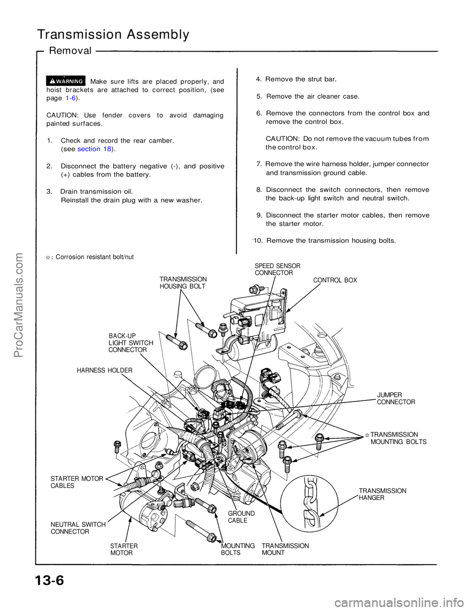
Corrosion resistant bolt/nut
TRANSMISSION
HOUSING BOLT
BACK-UP
LIGHT SWITCH
CONNECTOR
HARNESS HOLDER
STARTER MOTOR
CABLES
NEUTRAL SWITCH
CONNECTOR
STARTER
MOTOR
MOUNTING
BOLTS
TRANSMISSION
MOUNT
GROUND
CABLE
TRANSMISSION
HANGER
TRANSMISSION
MOUNTING BOLTS
JUMPER
CONNECTOR
CONTROL BOX
SPEED SENSOR
CONNECTOR
4. Remove the strut bar.
5. Remove the air cleaner case.
6. Remove the connectors from the control box and remove the control box.
CAUTION: Do not remove the vacuum tubes from
the control box.
7. Remove the wire harness holder, jumper connector and transmission ground cable.
8. Disconnect the switch connectors, then remove the back-up light switch and neutral switch.
9. Disconnect the starter motor cables, then remove the starter motor.
10. Remove the transmission housing bolts.ProCarManuals.com
Page 1544 of 1640
BEARING OUTER RACE
75 mm THRUST SHIM
Selection.
CLAMP
BACK-UP LIGHT SWITCH
25 N·m (2.5 kg-m, 18 Ib-ft)
CLAMP
TRANSMISSION HANGER A
TRANSMISSION HANGER B
STAY
WASHER
Replace.
OIL FILLER PLUG
45 N·m (4.5 kg-m, 33 Ib-ft)
42 x 63 x 12.5 mm OIL SEAL
Replace.
WASHER
Replace.
DRAIN PLUG
40 N·m (4.0 kg-m, 29 Ib-ft) 36 mm SEALING BOLT
35 N·m (3.5 kg-m. 25 Ib-ft)
STRAINER COVER O-RING
Replace.
STRAINER SET SPRING
OIL PUMP STRAINER
14 mm SEALING BOLT
33 N·m (3.3 kg-m. 24 Ib-ft)
SPRING (L. 25 mm)
STEEL BALL (LARGE) 16 mm SEALING BOLT
42 N·m (4.2 kg-m, 30 Ib-ft) SPRING (L. 24.2 mm)
16 mm SEALING BOLTS
42 N·m (4.2 kg-m, 30 Ib-ft)
SPRING (L. 30 mm)
STEEL BALL (SMALL)
SHIFT LEVER ASSEMBLY
0 Removal, page
13-17
• Installation, page 13-43
NEUTRAL SWITCH
25 N·m (2.5 kg-m, 18 Ib-ft)
TRANSMISSION HOUSING
OIL GUIDE PLATE
82 mm THRUST SHIM
• Selection, page
13-41
ProCarManuals.com