Page 1200 of 2103
AUTOMATIC TRANSAXLE
ENGINE (NON-TURBO)> Transaxle Assembly
TRANSAXLE ASSEMBLY
l Transaxle Fluid Draining
l Transaxle Fluid Draining
(Refer to GROUP 00 Maintenance service)
(Refer to GROUP 00 Maintenance service)
l Battery Removal
l Battery Removal
l Under Cover Removal
l Under Cover Removal
(Refer to GROUP 42
Under Cover)
(Refer to GROUP 42 Under Cover)
7454
Post-installation Operationl Under Cover Installation
(Refer to GROUP Under Cover)
l Battery Installation
l Transaxle Fluid Supplying
(Refer to GROUP 00
Maintenance Service)
l Selector Lever Operation Check
9.2
6
5140
69 Nm51 I
42
51
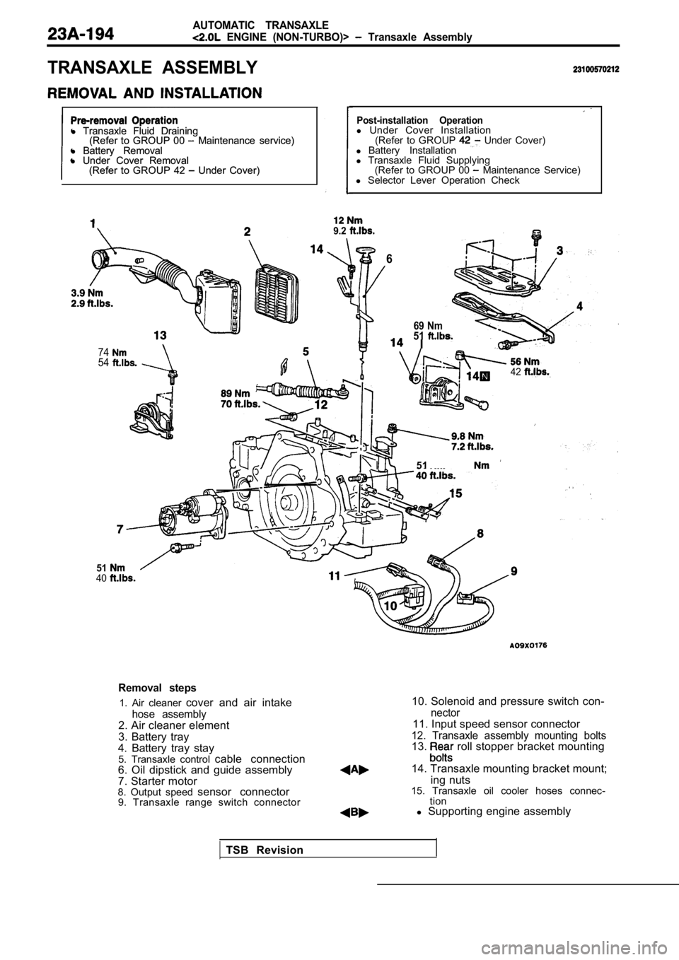
Removal steps
1. Air cleaner cover and air intake
hose assembly2. Air cleaner element
3. Battery tray
4. Battery tray stay 5. Transaxle control cable connection
6. Oil dipstick and guide assembly
7. Starter motor
8. Output speed sensor connector
9. Transaxle range switch connector
10. Solenoid and pressure switch con-
nector11. Input speed sensor connector
12. Transaxle assembly mounting bolts13. roll stopper bracket mounting
14. Transaxle mounting bracket mount; ing nuts
15. Transaxle oil cooler hoses connec- tion
l Supporting engine assembly
TSB Revision
Page 1204 of 2103
AUTOMATIC TRANSAXLE
ENGINE (NON-TURBO)> -Transaxle Oil Cooler
TRANSAXLE OIL COOLER
and Post-installation
Transaxle Fluid Draining and
(Refer to GROUP 00 Maintenance
2
3.9 Nm2.9
Removal steps
1. Air cleaner cover and air intake
hose
2.Hose3. Pipe assembly
lCheck the hose for cracks, damage and clogs.
lCheck for rusted or clogged transaxle oil cooler.
l Check oil cooler fins for bents, damage, and clogge d
with foreign matter.
TSB Revision
Page 1521 of 2103
B.J.
FRONT AXLE Drive Shaft
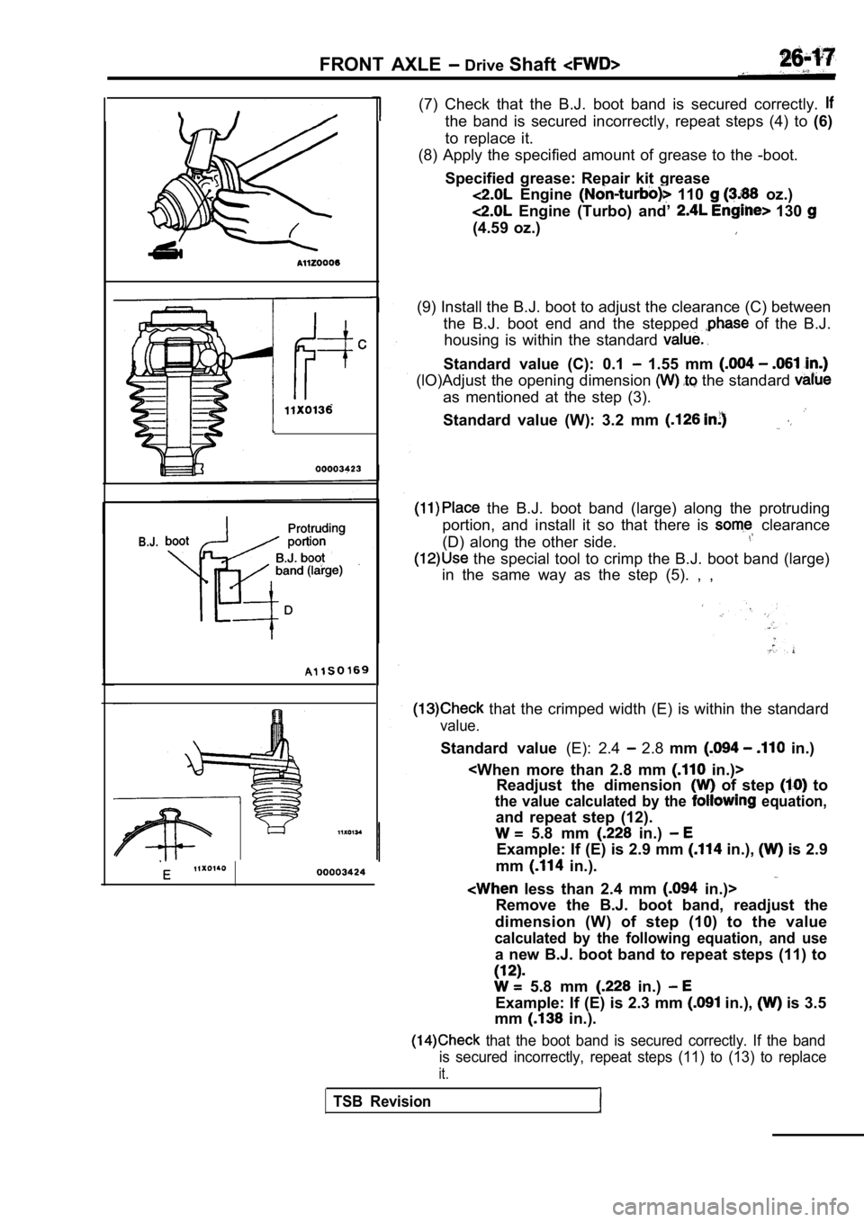
(7) Check that the B.J. boot band is secured correc tly.
the band is secured incorrectly, repeat steps (4) to (6)
to replace it.
(8) Apply the specified amount of grease to the -bo ot.
Specified grease: Repair kit grease
Engine 110 oz.)
Engine (Turbo) and’ 130
(4.59 oz.)
(9) Install the B.J. boot to adjust the clearance ( C) between
the B.J. boot end and the stepped
of the B.J.
housing is within the standard
Standard value (C): 0.1 1.55 mm
(lO)Adjust the opening dimension the standard
as mentioned at the step (3).
Standard value (W): 3.2 mm
the B.J. boot band (large) along the protruding
portion, and install it so that there is
clearance
(D) along the other side.
the special tool to crimp the B.J. boot band (larg e)
in the same way as the step (5). , ,
that the crimped width (E) is within the standard
value.
Standard value (E): 2.4 2.8 mm in.)
in.)>
Readjust the dimension
of step to
the value calculated by the equation,
and repeat step (12).
5.8 mm in.)
Example: If (E) is 2.9 mm in.), is 2.9
mm
in.).
less than 2.4 mm in.)>
Remove the B.J. boot band, readjust the
dimension (W) of step (10) to the value
calculated by the following equation, and use
a new B.J. boot band to repeat steps (11) to
5.8 mm in.)
Example: If (E) is 2.3 mm in.), is 3.5
mm
in.).
that the boot band is secured correctly. If the ba nd
is secured incorrectly, repeat steps (11) to (13) t o replace
it.
TSB Revision
Page 1522 of 2103
FRONT AXLE Drive Shaft
B.J.Dynamicbamper
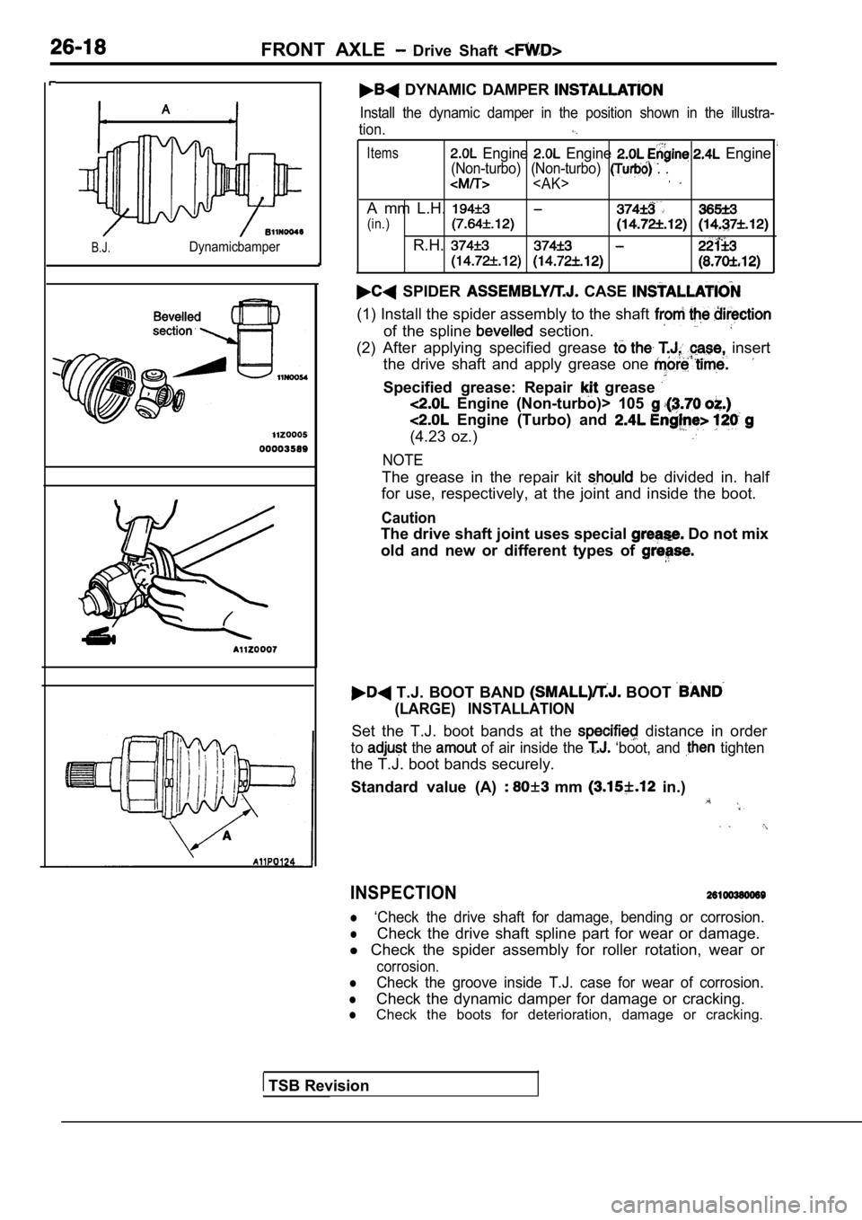
DYNAMIC DAMPER
Install the dynamic damper in the position shown in the illustra-
tion.
Items Engine Engine Engine
(Non-turbo) (Non-turbo) . .
A mm L.H.
(in.)
R.H.
SPIDER CASE
(1) Install the spider assembly to the shaft
of the spline section.
(2) After applying specified grease insert
the drive shaft and apply grease one
Specified grease: Repair grease
Engine (Non-turbo)> 105
Engine (Turbo) and
(4.23 oz.)
NOTE
The grease in the repair kit be divided in. half
for use, respectively, at the joint and inside the boot.
Caution
The drive shaft joint uses special Do not mix
old and new or different types of
T.J. BOOT BAND BOOT
(LARGE) INSTALLATION
Set the T.J. boot bands at the distance in order
to the of air inside the ‘boot, and tighten
the T.J. boot bands securely.
Standard value (A)
mm in.)
INSPECTION
l‘Check the drive shaft for damage, bending or corro sion.
lCheck the drive shaft spline part for wear or damage.
l Check the spider assembly for roller rotation, wear or
corrosion.
lCheck the groove inside T.J. case for wear of corro sion.
lCheck the dynamic damper for damage or cracking.
lCheck the boots for deterioration, damage or cracking.
TSB Revision
Page 1549 of 2103
R E A R
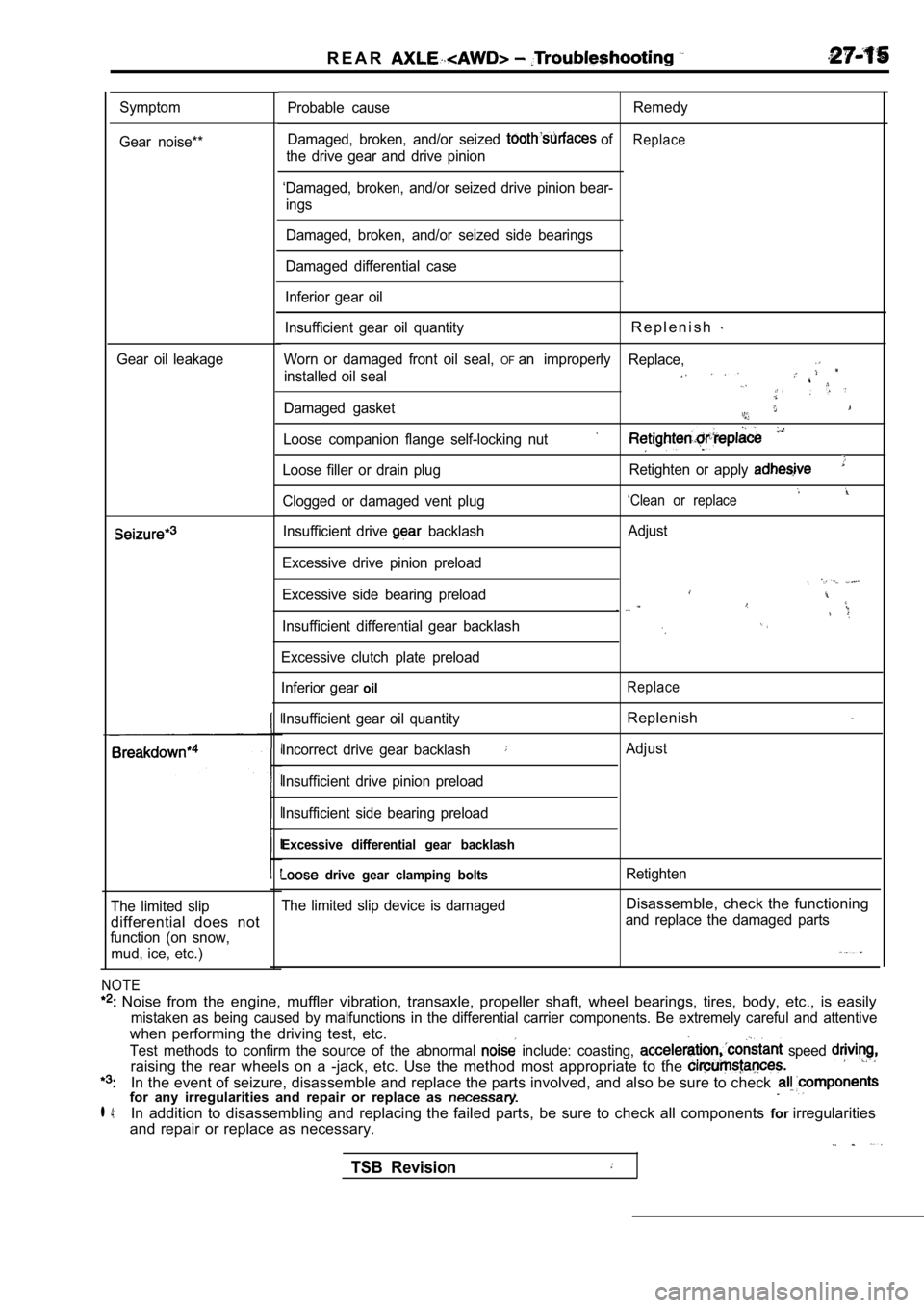
Symptom
Gear noise**
Gear oil leakage
The limited slip
differential does not
function (on snow, mud, ice, etc.)
NOTE
Noise from the engine, muffler vibration, transaxl e, propeller shaft, wheel bearings, tires, body, etc., is easily
mistaken as being caused by malfunctions in the dif ferential carrier components. Be extremely careful and attentive
when performing the driving test, etc.
Test methods to confirm the source of the abnormal include: coasting, speed
raising the rear wheels on a -jack, etc. Use the me thod most appropriate to the
In the event of seizure, disassemble and replace the parts involved, and also be sure to check for any irregularities and repair or replace as
l 4:In addition to disassembling and replacing the failed parts, be sure to check all components forirregularities
and repair or replace as necessary.
Probable cause Remedy
Damaged, broken, and/or seized
ofReplace
the drive gear and drive pinion
‘Damaged, broken, and/or seized drive pinion bear- ings
Damaged, broken, and/or seized side bearings
Damaged differential case
Inferior gear oil
Insufficient gear oil quantity
R e p l e n i s h
Worn or damaged front oil seal, OFan improperly Replace,
installed oil seal
Damaged gasket
Loose companion flange self-locking nut
Loose filler or drain plug Retighten or apply
‘Clean or replaceClogged or damaged vent plug
Insufficient drive
backlash
Excessive drive pinion preload
Excessive side bearing preload
Insufficient differential gear backlash
Excessive clutch plate preload
Inferior gear
oil
Insufficient gear oil quantity
Incorrect drive gear backlash
Insufficient drive pinion preload
Insufficient side bearing preload
Excessive differential gear backlash
drive gear clamping bolts
The limited slip device is damaged Adjust
Replace
Replenish
Adjust
Retighten
Disassemble, check the functioning
and replace the damaged parts
TSB Revision
Page 1594 of 2103
32-4P O W E R P L A N T M O U N T
REMOVAL AND INSTALLATION
OperationJack Up the Engine and Transaxle Assembly Until Thereis no Weight on the Engine Mount Bracket Insulator.
Engine (Non-turbo)>
86
63
9871
Removal steps
1. Enaine mount insulator mounting
2. Engine mount bracket 3. Engine mount stopper
Engine sideEngine
mount Engine
mount
stopper
______ .bracket
Engine (Turbo) and Engine>
87 .
,
9871 85
INSTALLATION POINT
ENGINE MOUNT
Align the notches on the stopper with the engine bracket
with the arrow mark facing toward the shown
install the stopper.
,
INSPECTION
lCheck each insulator for cracks or damage.
lCheck each bracket for deformations or damage.
TSB Revision
Page 1598 of 2103
32-8POWER PLANT MOUNT Engine Roll. Stopper,
(1) Set the special tool to the to the engine
assembly.
(2) Remove the centermember assembly.
INSTALLATION POINT
FRONT
If the dimension shown in the illustration the standard
value when the weight of the engine is the body, replace
the front roll stopper bracket
Standard value (A):
I.
INSPECTION
l each insulator for cracks damage.
l Check each bracket for
damage.
,
.
,
,
Revision
Page 1646 of 2103
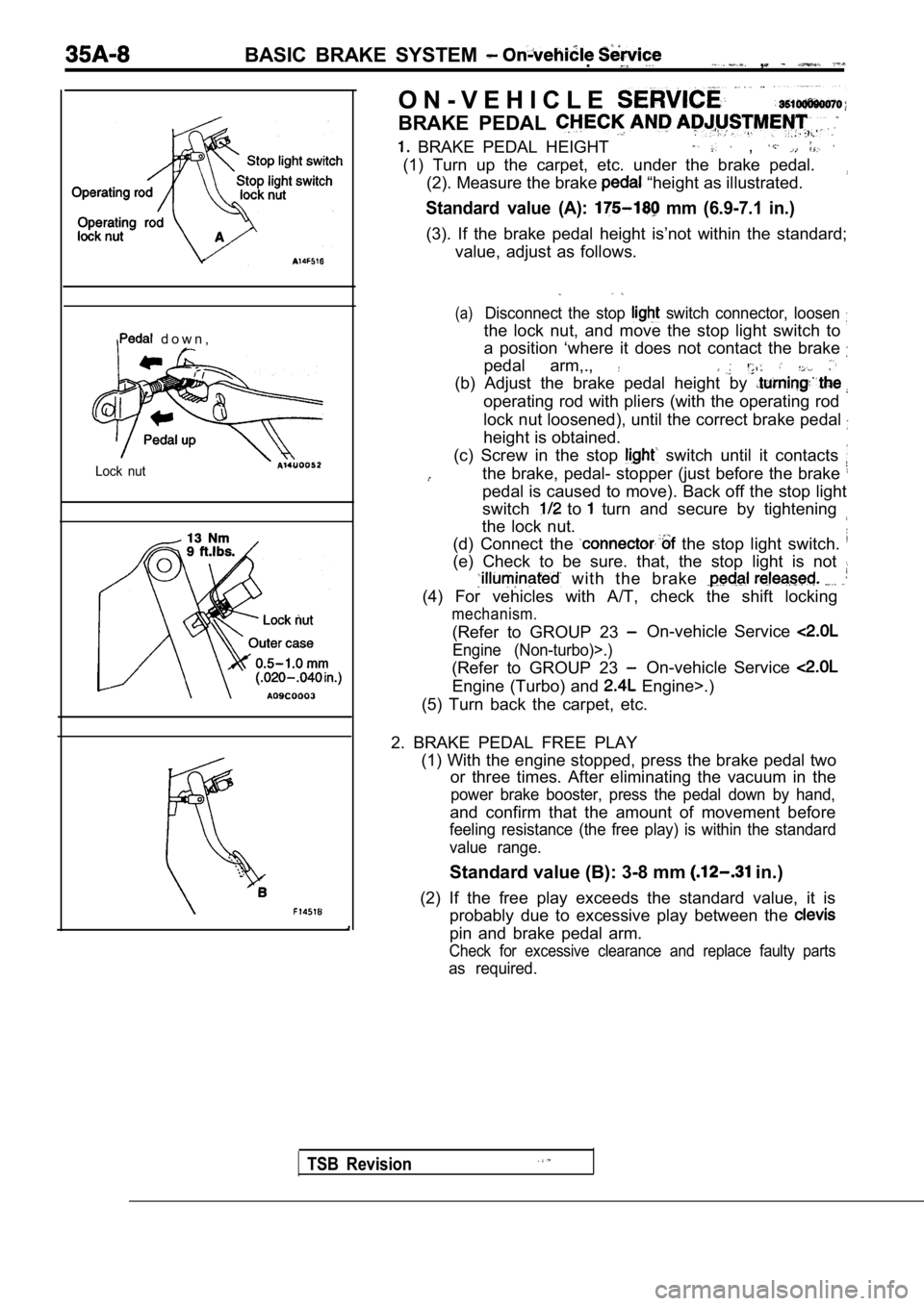
BASIC BRAKE SYSTEM .,
d o w n ,
Lock nut
TSB Revision
O N - V E H I C L E
BRAKE PEDAL
BRAKE PEDAL HEIGHT ,
(1) Turn up the carpet, etc. under the brake pedal.(2). Measure the brake
“height as illustrated.
Standard value (A): mm (6.9-7.1 in.)
(3). If the brake pedal height is’not within the st andard;
value, adjust as follows.
(a)Disconnect the stop switch connector, loosen
the lock nut, and move the stop light switch to
a position ‘where it does not contact the brake
pedal arm,.,
(b) Adjust the brake pedal height by
operating rod with pliers (with the operating rod
lock nut loosened), until the correct brake pedal
height is obtained.
(c) Screw in the stop
switch until it contacts
the brake, pedal- stopper (just before the brake
pedal is caused to move). Back off the stop light
switch
to turn and secure by tightening
the lock nut.
(d) Connect the
the stop light switch.
(e) Check to be sure. that, the stop light is not
with the brake
(4) For vehicles with A/T, check the shift locking
mechanism.
(Refer to GROUP 23 On-vehicle Service
Engine (Non-turbo)>.)
(Refer to GROUP 23 On-vehicle Service
Engine (Turbo) and Engine>.)
(5) Turn back the carpet, etc.
2. BRAKE PEDAL FREE PLAY (1) With the engine stopped, press the brake pedal two
or three times. After eliminating the vacuum in the
power brake booster, press the pedal down by hand,
and confirm that the amount of movement before
feeling resistance (the free play) is within the st andard
value range.
Standard value (B): 3-8 mm in.)
(2) If the free play exceeds the standard value, it is
probably due to excessive play between the
pin and brake pedal arm.
Check for excessive clearance and replace faulty pa rts
as required.