1990 MITSUBISHI SPYDER check engine
[x] Cancel search: check enginePage 1752 of 2103
On-vehicle
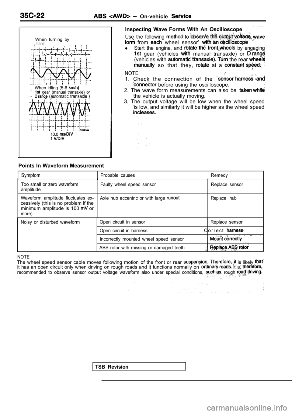
When turning by, hand
-:--‘---t---i-.-i-.-;----~---!---
--!-4--
When idling (5-6 gear (manual transaxle) or (automatic transaxle
10.01
Inspecting Wave Forms With An Oscilloscope
Use the following to wave
from wheel sensor’
lStart the engine, and by engaging
gear (vehicles manual transaxle) or
(vehicles with the rear
so that they, at a
NOTE
1. Check the connection of the
before using the oscilloscope.,
2. The wave form measurements can also be
the vehicle is actually moving.
3. The output voltage will be low when the wheel sp eed
‘is low, and similarly it will be higher as the whe el speed
Points In Waveform Measurement
SymptomProbable causesRemedy
Too small or zero waveform
amplitude
Waveform amplitude fluctuates ex-
cessively (this is no problem if the minimum amplitude is 100
or
more)
Faulty wheel speed sensor
TSB Revision
Axle hub eccentric or with large
Replace sensor
Replace hub
Noisy or disturbed waveform Open circuit in sensor
Open circuit in harness Replace sensor
C o r r e c t
Incorrectly mounted wheel speed sensor
ABS rotor with missing or damaged teeth
NOTE
The wheel speed sensor cable moves following motion of the front or rear is likely . . . . . it has an open circuit only when driving on rough roads and it functions normally on It IS,
recommended to observe sensor output voltage wavefo rm also under special conditions, rough
Page 1756 of 2103
ABS On-vehicle Service
ABS-ECU
14
32
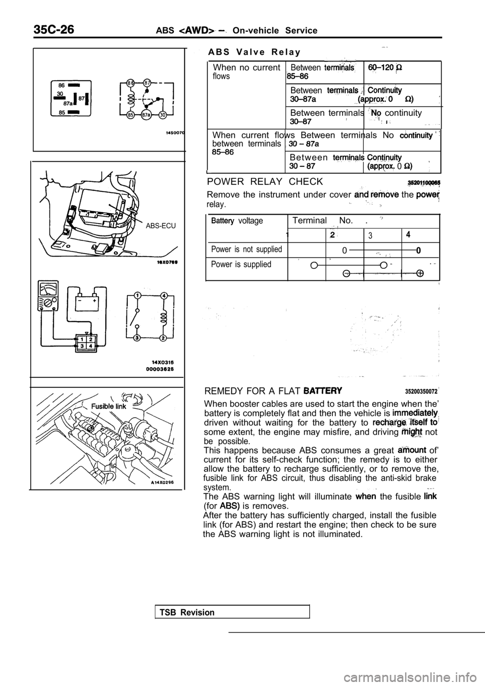
A B S V a l v e R e l a y
When no current
flows
Between
Between
Between terminals continuity
When current flows Between terminals No
between terminals
B e t w e e n
0
POWER RELAY CHECK
Remove the instrument under cover the
relay.
voltageTerminal No. .
34
Power is not supplied00
Power is supplied.
REMEDY FOR A FLAT ,35200350072
When booster cables are used to start the engine wh en the’
battery is completely flat and then the vehicle is
driven without waiting for the battery to
some extent, the engine may misfire, and driving not
be possible.
This happens because ABS consumes a great of’
current for its self-check function; the remedy is to either
allow the battery to recharge sufficiently, or to r emove the,
fusible link for ABS circuit, thus disabling the an ti-skid brake
system.
The ABS warning light will illuminate the fusible
(for is removes.
After the battery has sufficiently charged, install the fusible
link (for ABS) and restart the engine; then check t o be sure
the ABS warning light is not illuminated.
TSB Revision
Page 1775 of 2103
CONTENTS
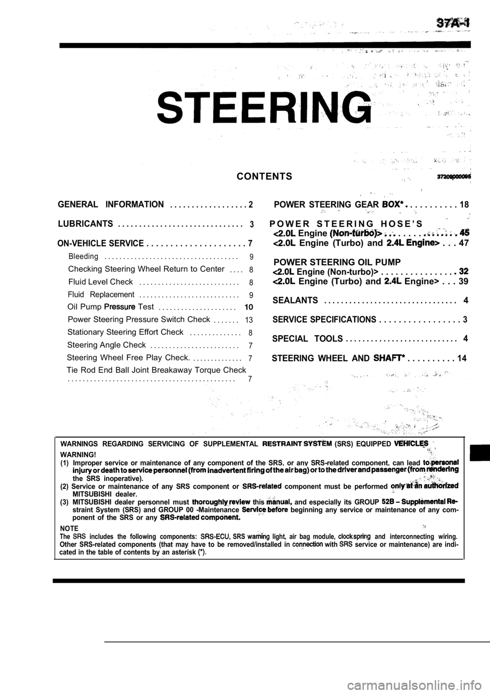
GENERAL INFORMATION. . . . . . . . . . . . . . . . . . 2POWER STEERING GEAR . . . . . . . . . . 18
LUBRICANTS. . . . . . . . . . . . . . . . . . . . . . . . . . . . . .
3P O W E R S T E E R I N G H O S E ’ S
Engine . . . . .
ON-VEHICLE SERVICE . . . . . . . . . . . . . . . . . . . . . 7 Engine (Turbo) and . . . 47
Bleeding. . . . . . . . . . . . . . . . . . . . . . . . . . . . . . . . . . . .9
Checking Steering Wheel Return to Center
. . . .8
Fluid Level Check. . . . . . . . . . . . . . . . . . . . . . . . . . .8
Fluid Replacement. . . . . . . . . . . . . . . . . . . . . . . . . . .9
Oil Pump Test
. . . . . . . . . . . . . . . . . . . . .
Power Steering Pressure Switch Check
. . . . . . .13
Stationary Steering Effort Check. . . . . . . . . . . . . .8
Steering Angle Check. . . . . . . . . . . . . . . . . . . . . . . .7
Steering Wheel Free Play Check. . . . . . . . . . . . . . .7
Tie Rod End Ball Joint Breakaway Torque Check
. . . . . . . . . . . . . . . . . . . . . . . . . . . . . . . . . . . . . . . . . . . . .
7
POWER STEERING OIL PUMP
Engine (Non-turbo)> . . . . . . . . . . . . . . .
Engine (Turbo) and Engine> . . . 39
SEALANTS. . . . . . . . . . . . . . . . . . . . . . . . . . . . . . . .4
SERVICE SPECIFICATIONS . . . . . . . . . . . . . . . . . 3
SPECIAL TOOLS. . . . . . . . . . . . . . . . . . . . . . . . . . .4
STEERING WHEEL AND
. . . . . . . . . . 14
WARNINGS REGARDING SERVICING OF SUPPLEMENTAL (SRS) EQUIPPED
WARNING!(1)Improper service or maintenance of any component of the SRS, or any SRS-related component, can lead
the SRS inoperative).(2) Service or maintenance of any SRS component or component must be performed MITSUBISHI dealer.(3) MITSUBISHI dealer personnel must this and especially its GROUP straint System (SRS) and GROUP 00 -Maintenance beginning any service or maintenance of any com-
ponent of the SRS or any
NOTEThe includes the following components: SRS light, air bag module, and interconnecting wiring.Other SRS-related components (that may have to be r emoved/installed in with service or maintenance) are indi-
cated in the table of contents by an asterisk
Page 1778 of 2103
SEALANTS
Sealants/Special Tools
.
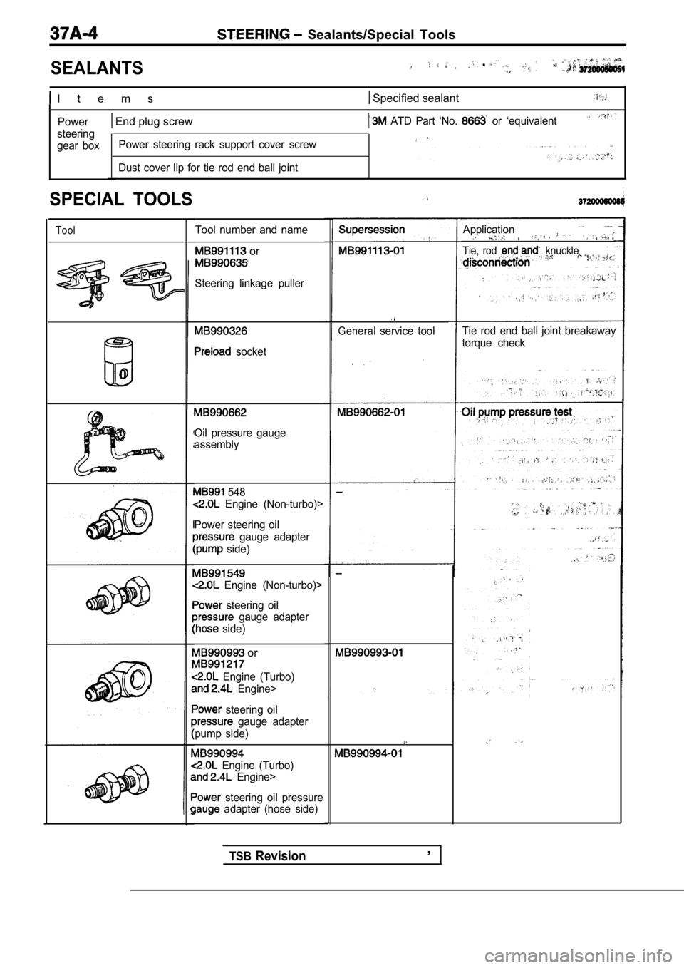
I t e m s Specified sealant
Power
steering
gear box End plug screw ATD Part ‘No. or ‘equivalent
Power steering rack support cover screw
Dust cover lip for tie rod end ball joint
SPECIAL TOOLS
Tool
0
Tool number and name
or
Steering linkage puller
socket
Oil pressure gauge
assembly
548
Engine (Non-turbo)>
Power steering oil
gauge adapter
side)
Engine (Non-turbo)>
steering oil
gauge adapter
side)
or
Engine (Turbo)
Engine>
steering oil
gauge adapter
pump side)
Engine (Turbo)
Engine>
steering oil pressure adapter (hose side)
Generalservice tool
TSBRevision,
Application
Tie, rod knuckle
Tie rod end ball joint breakaway
torque check
Page 1781 of 2103
STEERING On-vehicle”
TSB Revision
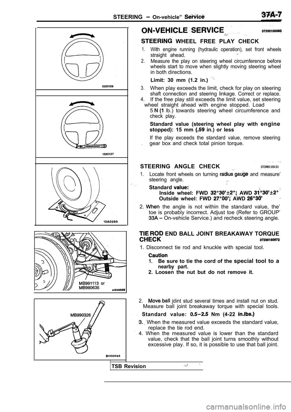
WHEEL FREE PLAY CHECK
1.With engine running (hydraulic operation), set front wheels
straight ahead.
2.Measure the play on steering wheel circumference be fore
wheels start to move when slightly moving steering wheel
in both directions.
Limit: 30 mm (1.2 in.)
3.When play exceeds the limit, check for play on steering
shaft connection and steering linkage. Correct or replace.
4.If the free play still exceeds the limit value, set steering
wheel straight ahead with engine stopped. Load
5
(1 lb.) towards steering wheel circumference and
check play.
Standard value (steering wheel play with engine
stopped): 15 mm
in.) or less
If the play exceeds the standard value, remove stee ring
. .gear box and check total pinion torque.
STEERING ANGLE CHECK
37200110131
1.Locate front wheels on turning and measure’
steering angle.
Standard
Inside wheel: FWD AWD
Outside wheel: FWD AWD
2. the angle is not within the standard value, the’
toe is probably incorrect. Adjust toe (Refer to GRO UP’
On-vehicle Service.) and recheck steering angle.
END BALL JOINT BREAKAWAY TORQUE
1. Disconnect tie rod and knuckle with special tool .
1.Be sure to tie the cord of the special tool to a
nearby part.
2. Loosen the nut but do not remove it.
2. jdint stud several times and install nut on stud.
Measure ball joint breakaway torque with special to ols.
Standard value:
Nm (4-22
When the measured value exceeds the standard value ,
replace the tie rod end.
4. When the measured value is lower than the standa rd
value, check that the ball joint turns smoothly wit hout
excessive play. If so, it is possible to use that b all joint.
Page 1782 of 2103
STEERING On-vehicle Service
S T E E R I N G
1. the vehicle stopped on a paved surface, turn
the steering wheel to the straight ahead ‘position.
2.Start the engine and set to 1,000
Caution
After checking the engine rpm., there
a
to the standard idling rpm.
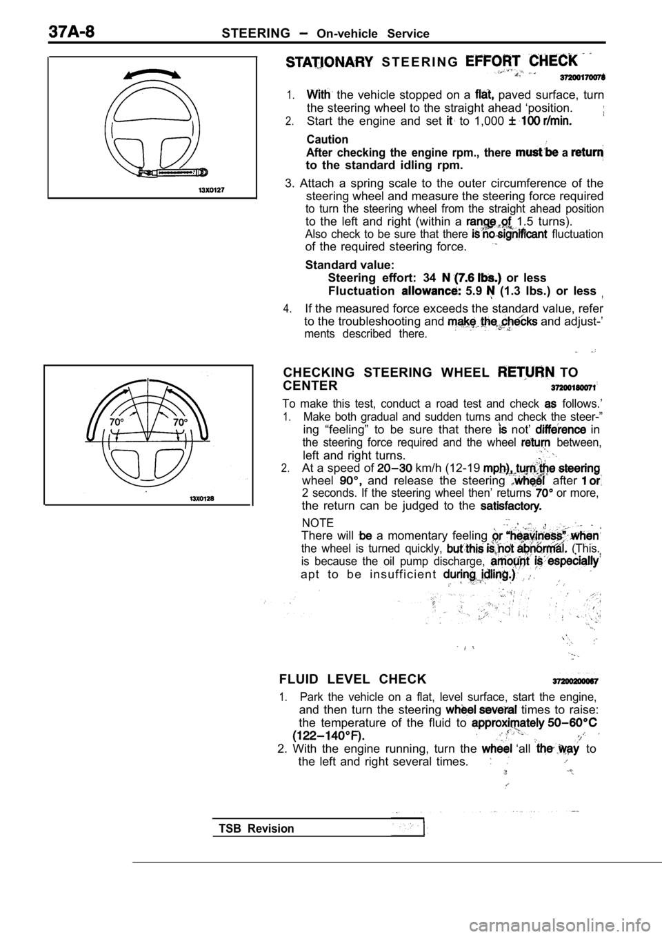
3. Attach a spring scale to the outer circumference of the
steering wheel and measure the steering force requi red
to turn the steering wheel from the straight ahead position
to the left and right (within a 1.5 turns).
Also check to be sure that there fluctuation
of the required steering force.
Standard value:
Steering effort: 34
or less
Fluctuation
5.9 (1.3 Ibs.) or less
4.If the measured force exceeds the standard value, r efer
to the troubleshooting and
and adjust-’
ments described there.
CHECKING STEERING WHEEL TO
CENTER
To make this test, conduct a road test and check follows.’
1.Make both gradual and sudden turns and check the st eer-”
ing “feeling” to be sure that there not’ in
the steering force required and the wheel between,
left and right turns.
2.At a speed of km/h (12-19
wheel and release the steering after
2 seconds. If the steering wheel then’ returns or more,
the return can be judged to the
NOTE ,
There will a momentary feeling
the wheel is turned quickly, (This.
is because the oil pump discharge,
a p t t o b e i n s u f f i c i e n t
FLUID LEVEL CHECK
1.Park the vehicle on a flat, level surface, start th e engine,
and then turn the steering times to raise:
the temperature of the fluid to
2. With the engine running, turn the ‘all to
the left and right several times.
TSB Revision
Page 1783 of 2103
STEERING On-vehicle
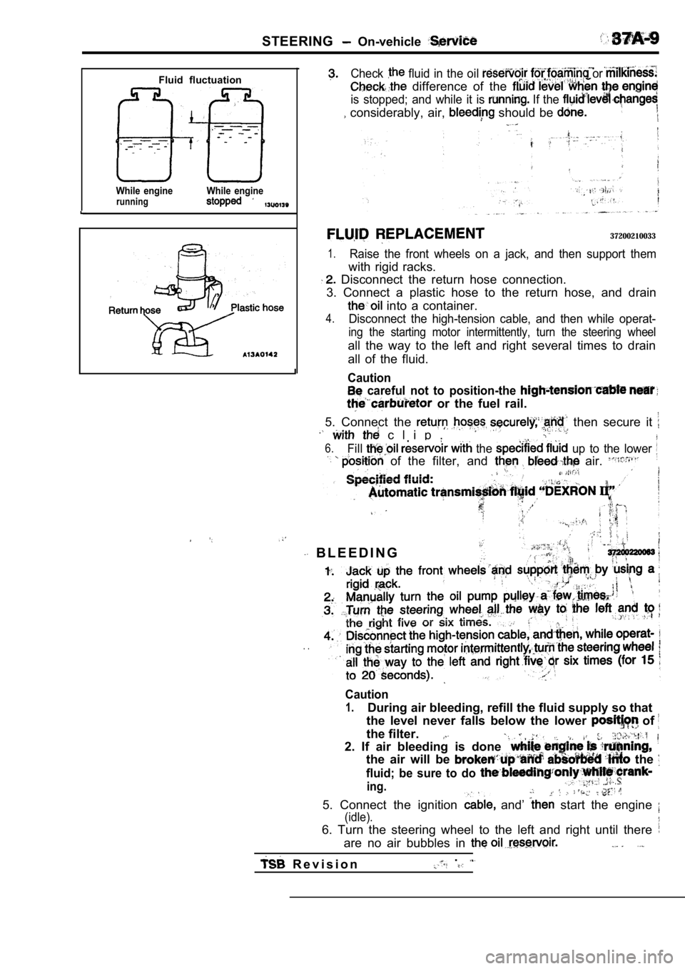
Fluid fluctuation
While enginerunningWhile engine
Check fluid in the oil or
difference of the
is stopped; and while it is If the
considerably, air, should be
37200210033
1.Raise the front wheels on a jack, and then support them
with rigid racks.
Disconnect the return hose connection.
3. Connect a plastic hose to the return hose, and d rain
into a container.
4.Disconnect the high-tension cable, and then while operat-
ing the starting motor intermittently, turn the steering wheel
all the way to the left and right several times to drain
all of the fluid.
Caution
careful not to position-the
or the fuel rail.
5. Connect the then secure it
c l i p .
6.Fill the up to the lower
of the filter, and air.
B L E E D I N G
. .
Caution
1.During air bleeding, refill the fluid supply so tha t
the level never falls below the lower
of
the filter.
2. If air bleeding is done
the air will be the
fluid; be sure to do
ing.
5. Connect the ignition and’ start the engine
(idle).
6. Turn the steering wheel to the left and right un til there
are no air bubbles in
R e v i s i o n.
Page 1784 of 2103
Fluid fluctuation
While engineWhile enginerunning stopped
PressureShut-off valv close)
NOTE
l l: Engine(Turbo) and Engine> 848 (Non-turbo)>
l 2: Engine (Turbo) and
Engine (Non-turbo)>
7. Confirm that fluid is the level
up the specified the
8. Confirm that there is change
when the steering wheel is turned,
9. Check whether or not in the fluid is
within 5 mm
in.) when the and
when it is running.
Caution
1. Ifthe change of
or more, the has bled,
from the system, and be bled ,
the fluid level rises suddenly after the engine,
stopped, the air has not completely
3.If air bleeding is not there will be
noises from the flow-control;
valve, ‘and
condition the life of,
the pump, etc.. ,
. . .
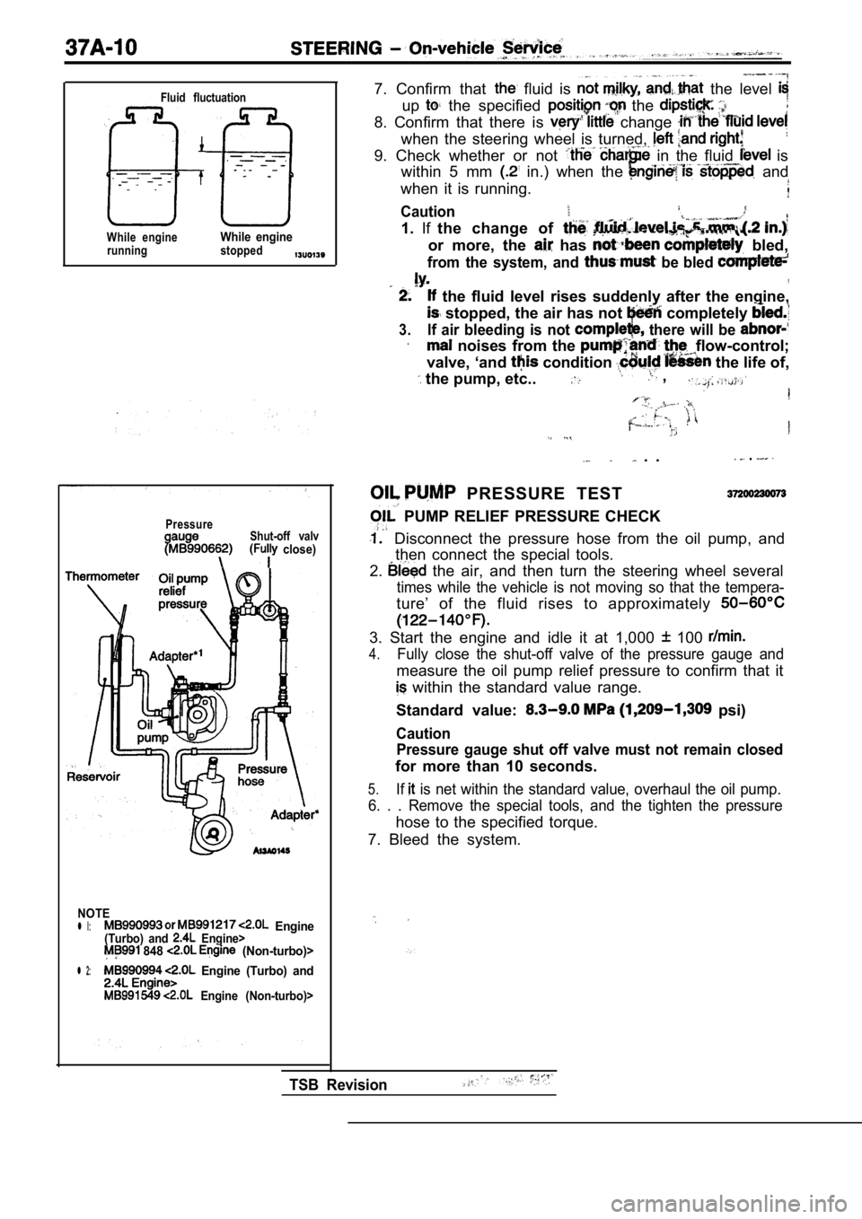
PRESSURE TEST
PUMP RELIEF PRESSURE CHECK
Disconnect the pressure hose from the oil pump, an d
then connect the special tools.
2.
the air, and then turn the steering wheel several
times while the vehicle is not moving so that the t empera-
ture’ of the fluid rises to approximately
3. Start the engine and idle it at 1,000 100
4.Fully close the shut-off valve of the pressure gaug e and
measure the oil pump relief pressure to confirm tha t it
within the standard value range.
Standard value:
psi)
Caution Pressure gauge shut off valve must not remain close d
for more than 10 seconds.
5.If is net within the standard value, overhaul the oil pump.
6. . . Remove the special tools, and the tighten th e pressure
hose to the specified torque.
7. Bleed the system.
TSB Revision