Page 1647 of 2103
BASIC BRAKE SYSTEM
CLEARANCEB E T W E E N B R A K E A N D
REWALL
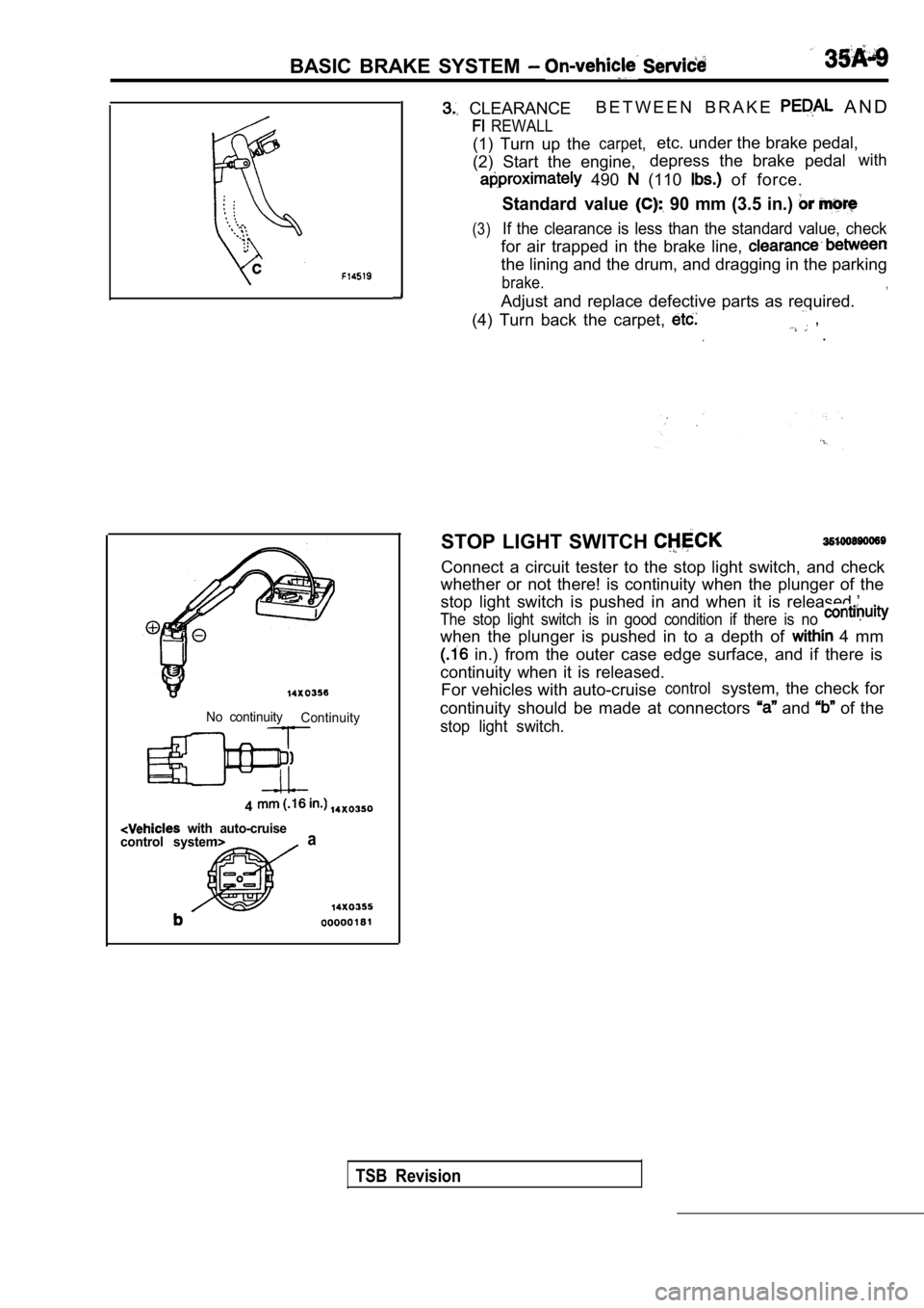
(1) Turn up thecarpet,etc. under the brake pedal,
(2) Start the engine, depress the brake pedal
with
490 (110 of force.
Standard value 90 mm (3.5 in.)
(3)If the clearance is less than the standard value, c
heck
for air trapped in the brake line,
the lining and the drum, and dragging in the parkin g
brake.
Adjust and replace defective parts as required.
(4) Turn back the carpet,
, .
No continuity Continuity
4
with auto-cruise
control systema
STOP LIGHT SWITCH
Connect a circuit tester to the stop light switch, and check
whether or not there! is continuity when the plunge r of the
stop light switch is pushed in and when it is relea sed.’
The stop light switch is in good condition if there is no
when the plunger is pushed in to a depth of 4 mm
in.) from the outer case edge surface, and if ther e is
continuity when it is released. For vehicles with auto-cruise
controlsystem, the check for
continuity should be made at connectors
and of the
stop light switch.
TSB Revision
Page 1648 of 2103
BASIC BRAKE SYSTEM On-vehicle Service
GoodNo good
000001
When engine isWhen engine isstopped started
No goodGood
00000184BRAKE BOOSTER OPERATING
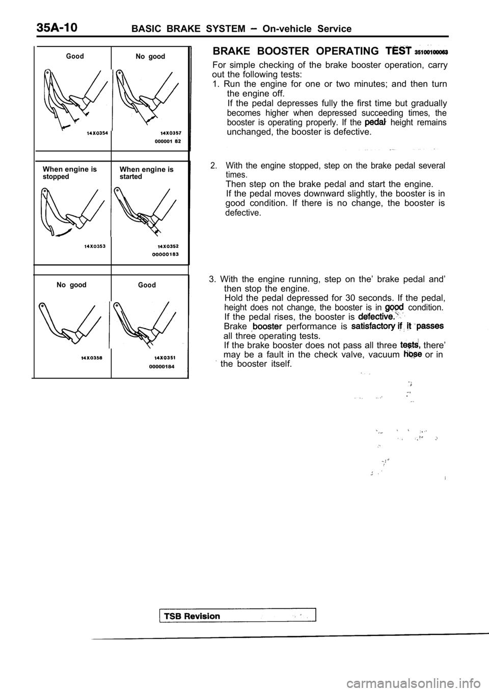
For simple checking of the brake booster operation,
carry
out the following tests: 1. Run the engine for one or two minutes; and then turn
the engine off. If the pedal depresses fully the first time but gra dually
becomes higher when depressed succeeding times, the
booster is operating properly. If the
height remains
unchanged, the booster is defective.
2.With the engine stopped, step on the brake pedal se veral
times.
Then step on the brake pedal and start the engine.
If the pedal moves downward slightly, the booster i s in
good condition. If there is no change, the booster is
defective.
3. With the engine running, step on the’ brake peda l and’
then stop the engine. Hold the pedal depressed for 30 seconds. If the ped al,
height does not change, the booster is in condition.
If the pedal rises, the booster is
Brake performance is
all three operating tests.
If the brake booster does not pass all three
there’
may be a fault in the check valve, vacuum
or in
the booster itself.
.
Page 1654 of 2103
BASIC BRAKE SYSTEM On-vehicle Service
Pad assembly
Grease
Grease Al
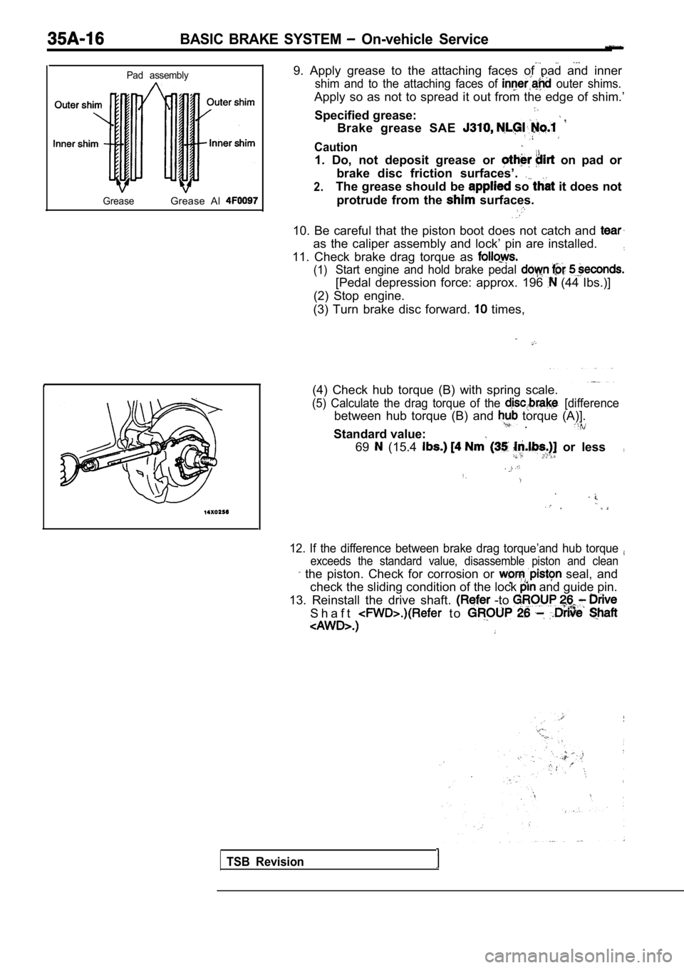
9. Apply grease to the attaching faces of pad and i nner
shim and to the attaching faces of outer shims.
Apply so as not to spread it out from the edge of shim.’
Specified grease:
Brake grease SAE
Caution
1. Do, not deposit grease or on pad or
brake disc friction surfaces’.
2.The grease should be so it does not
protrude from the
surfaces.
10. Be careful that the piston boot does not catch and
as the caliper assembly and lock’ pin are installed.
11. Check brake drag torque as
(1)Start engine and hold brake pedal
[Pedal depression force: approx. 196 (44 Ibs.)]
(2) Stop engine.
(3) Turn brake disc forward.
times,
(4) Check hub torque (B) with spring scale.
(5) Calculate the drag torque of the [difference
between hub torque (B) and torque (A)]. .
Standard value:
69 (15.4 or less,
12. If the difference between brake drag torque’and hub torque
exceeds the standard value, disassemble piston and clean
the piston. Check for corrosion or seal, and
check the sliding condition of the lock
and guide pin.
13. Reinstall the drive shaft.
-to
S h a f t t o
TSB Revision
Page 1660 of 2103
BASIC BRAKE SYSTEM On-vehicle Service
TSB Revision
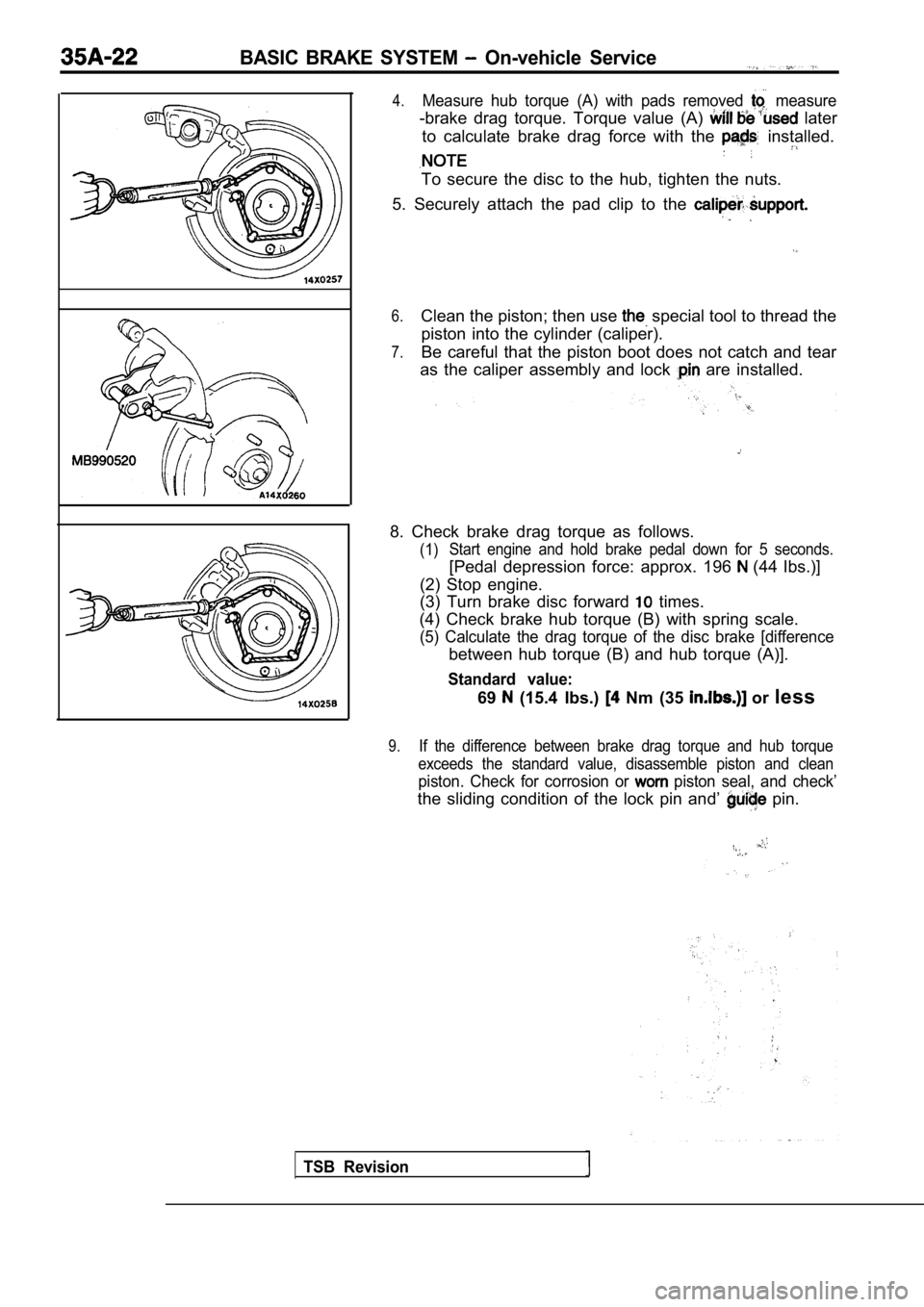
4.Measure hub torque (A) with pads removed measure
-brake drag torque. Torque value (A) later
to calculate brake drag force with the
installed.
To secure the disc to the hub, tighten the nuts.
5. Securely attach the pad clip to the
6.Clean the piston; then use special tool to thread the
piston into the cylinder (caliper).
7.Be careful that the piston boot does not catch and tear
as the caliper assembly and lock
are installed.
8. Check brake drag torque as follows.
(1) Start engine and hold brake pedal down for 5 second
s.
[Pedal depression force: approx. 196 (44 Ibs.)]
(2) Stop engine.
(3) Turn brake disc forward
times.
(4) Check brake hub torque (B) with spring scale.
(5) Calculate the drag torque of the disc brake [di fference
between hub torque (B) and hub torque (A)].
Standard value:
69 (15.4 Ibs.) Nm (35 or less
9.If the difference between brake drag torque and hub torque
exceeds the standard value, disassemble piston and clean
piston. Check for corrosion or piston seal, and check’
the sliding condition of the lock pin and’ pin.
Page 1663 of 2103
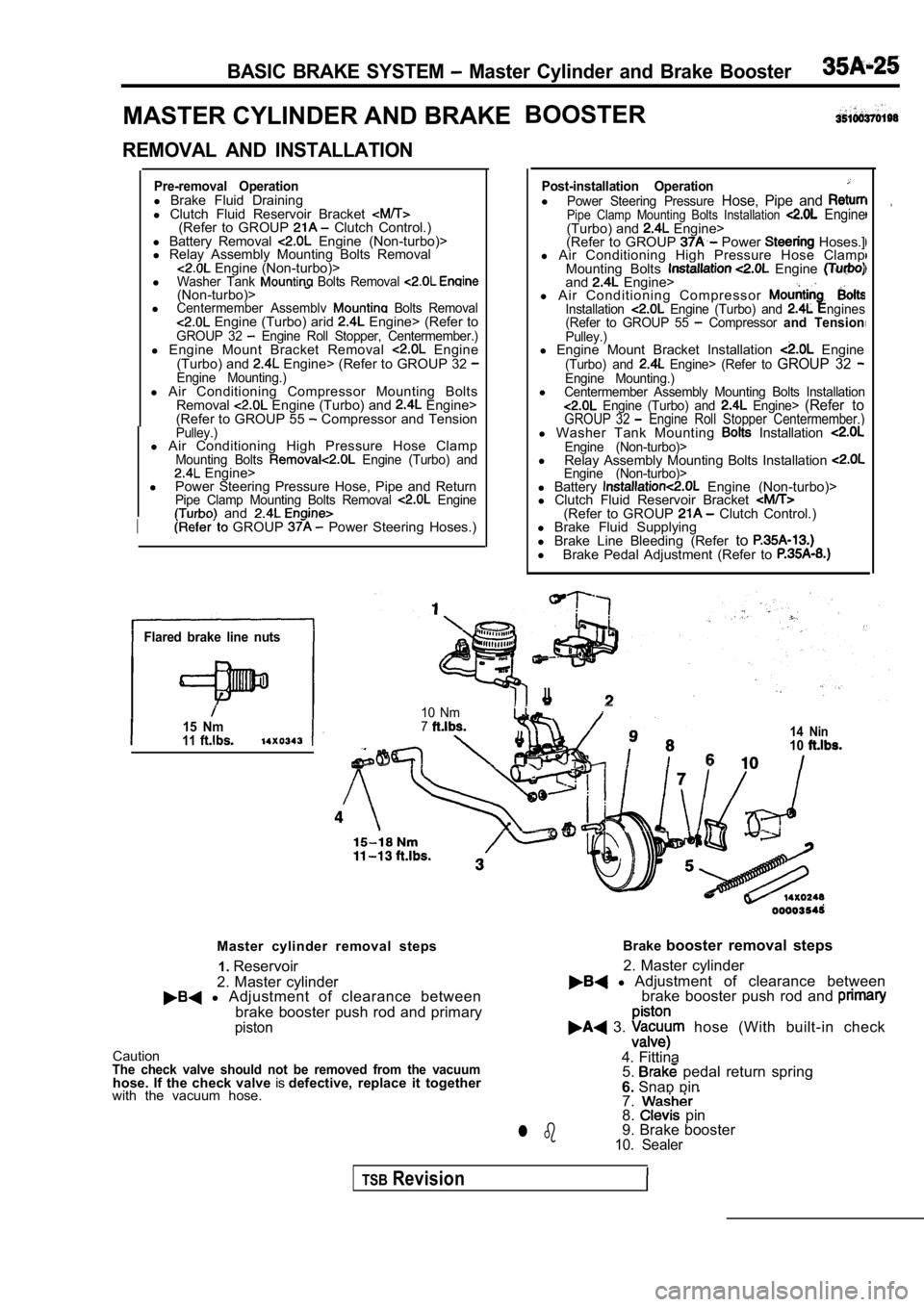
BASIC BRAKE SYSTEM Master Cylinder and Brake Booster
MASTER CYLINDER AND BRAKEBOOSTER
REMOVAL AND INSTALLATION
Pre-removal Operationl
Brake Fluid Draining
l Clutch Fluid Reservoir Bracket
(Refer to GROUP Clutch Control.)
l Battery Removal Engine (Non-turbo)>
l Relay Assembly Mounting Bolts Removal
Engine (Non-turbo)>
lWasher Tank Bolts Removal (Non-turbo)>lCentermember Assemblv Bolts Removal Engine (Turbo) arid Engine> (Refer toGROUP 32 Engine Roll Stopper, Centermember.)l Engine Mount Bracket Removal Engine
(Turbo) and Engine> (Refer to GROUP 32 Engine Mounting.)l Air Conditioning Compressor Mounting Bolts
Removal Engine (Turbo) and Engine>
(Refer to GROUP 55 Compressor and TensionPulley.)l Air Conditioning High Pressure Hose ClampMounting Bolts Engine (Turbo) and Engine>
l Power Steering Pressure Hose, Pipe and Return
Pipe Clamp Mounting Bolts Removal Engine and
I GROUP Power Steering Hoses.)
Flared brake line nuts
15 Nm11
Post-installation OperationlPower Steering Pressure Hose, Pipe and Pipe Clamp Mounting Bolts Installation Engine(Turbo) and Engine>
(Refer to GROUP Power Hoses.]
l Air Conditioning High Pressure Hose Clamp
Mounting Bolts
Engine and Engine>
l A i r C o n d i t i o n i n g C o m p r e s s o r
Installation Engine (Turbo) and ngines
(Refer to GROUP 55 Compressor and TensionPulley.)l Engine Mount Bracket Installation Engine(Turbo) and Engine> (Refer to GROUP 32 Engine Mounting.)lCentermember Assembly Mounting Bolts Installation Engine (Turbo) and Engine> (Refer toGROUP 32 Engine Roll Stopper Centermember.)l Washer Tank Mounting Installation Engine (Non-turbo)>l
Relay Assembly Mounting Bolts Installation Engine (Non-turbo)>l Battery Engine (Non-turbo)>
l Clutch Fluid Reservoir Bracket
(Refer to GROUP Clutch Control.)
l Brake Fluid Supplying
l Brake Line Bleeding (Refer to
l
Brake Pedal Adjustment (Refer to
I
10 Nm714 Nin10
Master cylinder removal steps
2. Master cylinder1.
Reservoir
l Adjustment of clearance between
brake booster push rod and primary
piston
CautionThe check valve should not be removed from the vacu umhose. If the check valve isdefective, replace it together
with the vacuum hose. Brake
booster removal steps
l Adjustment of clearance between
2. Master cylinder
brake booster push rod and
3. hose (With built-in check
4. Fittina 5.
pedal return spring
6. Snap pin
7.
8. pin
9. Brake booster
10. Sealerl b
TSBRevision
Page 1665 of 2103
BASIC BRAKE SYSTEM Master Cylinder arid Brake
m m
Marking
Prima
piston Push rod
Straight scale
- -
INSTALLATION SERVICE POINTS
HOSE CONNECTION
(1) Install the vacuum hose to the brake
nipple
shown in the figure. Secure the hose with the hose clip.
Caution
1. The check valve and the pipe part of
booster must not contact each other.
2. Connect so that the marking faces upwards.
(2) Install the other end of the vacuum hose fully onto its
port on the engine. Secure the hose using the hose clip.
CLEARANCE ADJUSTMENT BETWEEN BRAKE
BOOSTER PUSH ROD AND PRIMARY PISTON
Adjust the clearance (A) between the brake booster push
rod and
piston as follows:
Calculate clearance A from the
and measurements.
Standard value: mm in.)
NOTE
When brake booster negative pressure 67 (9.7 psi) is applied,
clearance value will become mm in.)
Straight scale
Page 1692 of 2103

ABS
TROUBLESHOOTING
DIAGNOSTIC TROUBLESHOOTING
Gather information from customer
.
Check diagnostic trouble code
(Refer to Check diagnostic trouble (Refer to
No diagnostic
trouble code or
with scan tool
Is the basic brake system functioning
normally?
Recheck trouble symptom.
Check diagnostic trouble codes
(Refer to
No diagnostictrouble
Inspection chart for trouble symptoms(Refer to Inspection chart for diagnostic troublecodes (Refer to
NOTES WITH REGARD TO DIAGNOSIS
The condition listed in the following table are con sidered normal.
ConditionExplanation of condition
No
.
TSB Revision
System check sound When starting the engine, a thudd
ing sound can sometimes be heard coming from inside.the engine compartment, but this is because the system operatioh check is being
performed. This is considered normal.
ABS operation sound
ABS operation (Long braking distance)1.Sound of the motor inside the ABS hydraulic unit. o perating (whine),
2. Sound is generated along with vibration of the b rake’ pedal.
3.When ABS operates, sound is generated from the vehi cle chassis due
brake application and release.
(Thump: suspension; squeak: tires)
For road surfaces such as snow-covered roads and gravel roads, the braking distance forvehicles with ABS can sometimes be longer than that for other vehicles. Accordingly,
advise the customer to drive safely on such roads by lowering the vehicle speed and not
being overconfident.
Diagnosis detection condition depends on the diagno stic trouble code.
Make sure that checking requirements listed in the “Comment” are satisfied when checking the trouble
symptom again after the diagnostic trouble code has been erased.
Page 1703 of 2103
ABS Troubleshooting
ABS WARNING LIGHT CHECK’
.
Check that the ABS warning light as-
1. When the ignition switch is turned
warning light illuminates..
2. When the ignition switch is turned to “START”, t
o
the engine, the ABS warning light
1 second.
3. If the is other’ above, check
diagnostic trouble codes.
Revision