Page 1158 of 2103
AUTOMATIC TRANSAXLE
ENGINE (NON-TURBO)>
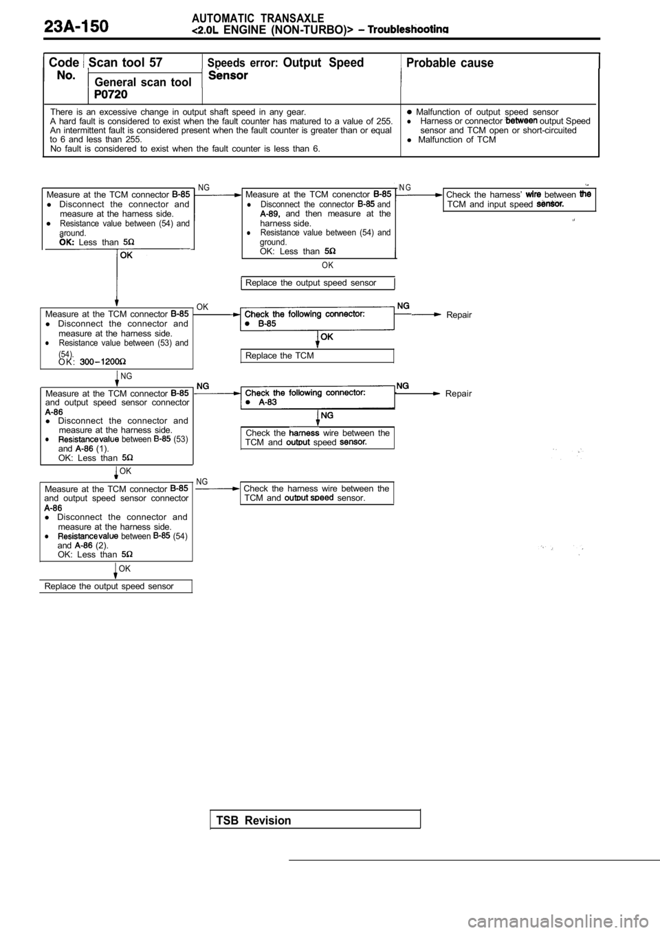
Code Scan tool 57 Speeds error: Output Speed Probable cause
General scan tool
There is an excessive change in output shaft speed in any gear. Malfunction of output speed sensor
A hard fault is considered to exist when the fault counter has matured to a value of 255.lHarness or connector output Speed
An intermittent fault is considered present when th e fault counter is greater than or equal sensor and TCM open or short-circuited
to 6 and less than 255. l Malfunction of TCM
No fault is considered to exist when the fault coun ter is less than 6.
Measure at the TCM connector
l Disconnect the connector and
measure at the harness side.
l
Resistance value between (54) and
around.
Measure at the TCM conenctor lDisconnect the connector and and then measure at the
harness side.
lResistance value between (54) and
ground. Less than
Measure at the TCM connector l Disconnect the connector and
measure at the harness side.
lResistance value between (53) and
(54).
OK
O K :
NG
OK: Less than
OK
Replace the output speed sensor
NG
Measure at the TCM connector and output speed sensor connector
l Disconnect the connector and
measure at the harness side.
l between (53)and (1).
OK: Less than
OK
Measure at the TCM connector and output speed sensor connector
l Disconnect the connector and
measure at the harness side.
l between (54)and (2).
OK: Less than
OK
Replace the output speed sensor
N G Check the harness’ between TCM and input speed
Check the following connector:Repair
Replace the TCM
Repair
Check the wire between the
TCM and speed
TSB Revision
NG Check the harness wire between the TCM and sensor.
Page 1160 of 2103
AUTOMATIC TRANSAXLE
ENGINE (NON-TURBO)> Troubleshooting
Code Scan tool 74Calculated oil temperature in use Probable cause
No.General scan tool
This code will set when the Transaxle Thermistor Voltage is below volts or abovel Malfunction of oil temperature sensor
4.9412 volts for 15 seconds, for 3 consecutive engi ne starts.l or connector between transaxle rangesensor and TCM open or short-circuited
l Malfunction of TCM
Oil temperature sensor check. (Refer to
NG Replace
N G
Measure at the transaxle range sensor Check
connector A-l 08 .
l Disconnect the connector and
measure at the harness side.OK
NG Repair
1. Voltage between (4) and ground.
l . 2 value between (3) and
transaxle range sensor and the TCM
Replace the TCM
Check the following connector: .NG Repair
OK
Check trouble symptom.
NGCheck the harness wire between the Repair
transaxle range sensor and the TCM
TSB Revision
Page 1165 of 2103
AUTOMATIC TRANSAXLE
ENGINE (NON-TURBO)>
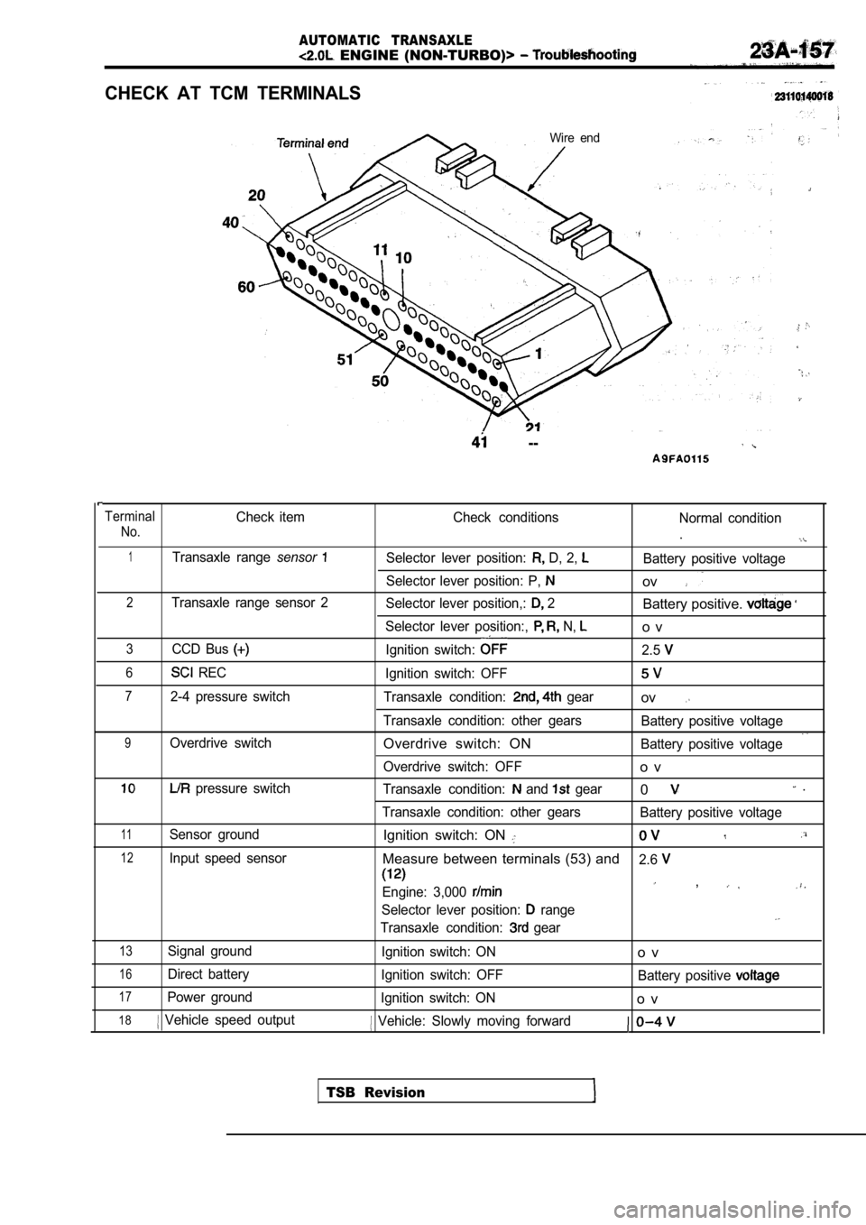
CHECK AT TCM TERMINALS
Wire end
--
TerminalCheck itemCheck conditions
Normal condition
No..
1Transaxle range sensorSelector lever position: D, 2, Battery positive voltage
Selector lever position: P,
ov
2Transaxle range sensor 2 Selector lever position,: 2Battery positive.
Selector lever position:, N, o v
3CCD Bus Ignition switch: 2.5
6 RECIgnition switch: OFF
72-4 pressure switch Transaxle condition: gearov
Transaxle condition: other gears Battery positive voltage
9Overdrive switchOverdrive switch: ONBattery positive voltage
Overdrive switch: OFF
o v
pressure switch Transaxle condition: and gear0 .
Transaxle condition: other gears Battery positive voltage
11Sensor groundIgnition switch: ON
12Input speed sensorMeasure between terminals (53) and2.6
Engine: 3,000 ,
Selector lever position: range
Transaxle condition: gear
13Signal ground
Ignition switch: ONo v
16Direct batteryIgnition switch: OFF Battery positive
17Power groundIgnition switch: ONo v
18 Vehicle speed output Vehicle: Slowly moving forward
TSB Revision
Page 1166 of 2103
AUTOMATIC TRANSAXLE
ENGINE Troubleshootina
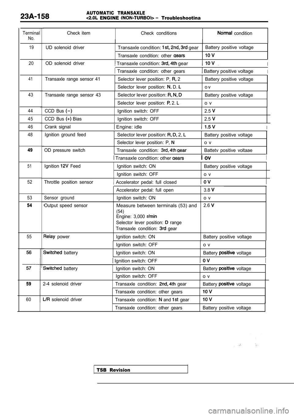
Terminal
No.19
Check item Check conditions condition
UD solenoid driver
Transaxle condition: gearBattery positive voltage
Transaxle condition: other
20OD solenoid driver Transaxle condition: gearI
Transaxle condition: other gears Battery positive voltageI
41Transaxle range sensor 41 Selector lever position: P, 2 Battery positive voltage
Selector lever position:
D. o v
43Transaxle range sensor 43Selector lever position: Battery positive voltage
Selector lever position:
2. o v
44
45
46
48CCD Bus Ignition switch: OFF 2.5
CCD Bus Bias Ignition switch: OFF 2.5
Crank signal Engine: idleI
Ignition ground feed
OD pressure switchSelector lever position: 2, Battery positive voltage
Selector lever position: P,
o v
Transaxle condition: Battetv positive voltaae49
Transaxle condition: other I ovI
51Ignition Feed Ignition switch: ON Battery positive voltage
Ignition switch: OFF
o v
52Throttle position sensor Accelerator pedal: full closedI
53
54
55 Sensor ground
Output speed sensor
power Accelerator pedal: full open 3.8
Ignition switch: ONo v
Measure between terminals (53) and
2.6
(54)
Engine: 3,000
Selector lever position: range
Transaxle condition:
gear
Ignition switch: ON Battery positive voltage
TSB Revision
battery Ignition switch: OFF
o v
Ignition switch: ON
Battery voltage
Ignition switch: OFFI
batteryIgnition switch: ON Battery voltage
Ignition switch: OFF
o v
592-4 solenoid driver Transaxle condition: gearBattery voltage
60 solenoid driver Transaxle condition: other gearsTransaxle condition: and gear
Transaxle condition: other gearsBattery positive voltage
Page 1167 of 2103
AUTOMATIC TRANSAXLE
ENGINE (NON-TURBO)>
.
to GROU’P 00
RefertoGROUP 00 Maintenance Service.
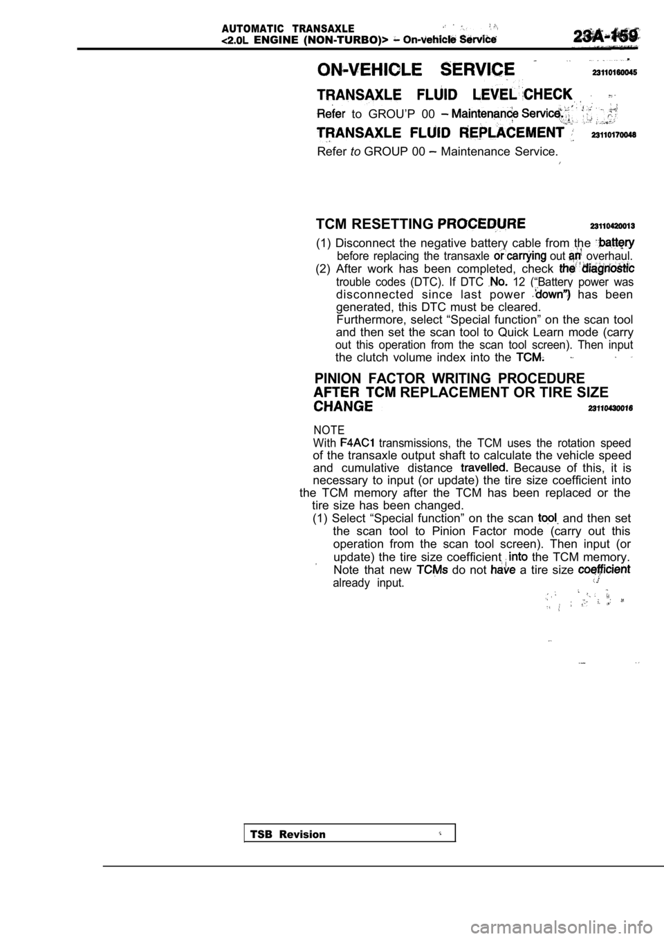
TCM RESETTING
(1) Disconnect the negative battery cable from the
before replacing the transaxle out overhaul.
(2) After work has been completed, check
trouble codes (DTC). If DTC 12 (“Battery power was
disconnected since last power has been
generated, this DTC must be cleared. Furthermore, select “Special function” on the scan tool
and then set the scan tool to Quick Learn mode (car ry
out this operation from the scan tool screen). Then input
the clutch volume index into the
PINION FACTOR WRITING PROCEDURE
REPLACEMENT OR TIRE SIZE
NOTE
With transmissions, the TCM uses the rotation speed
of the transaxle output shaft to calculate the vehicle speed
and cumulative distance
Because of this, it is
necessary to input (or update) the tire size coeffi cient into
the TCM memory after the TCM has been replaced or t he
tire size has been changed.
(1) Select “Special function” on the scan
and then set
the scan tool to Pinion Factor mode (carry out this operation from the scan tool screen). Then input (o r
update) the tire size coefficient the TCM memory.
Note that new
do not a tire size
already input.
TSB Revision
Page 1168 of 2103
AUTOMATIC TRANSAXLE
ENGINE (NON-TURBO)> On-vehicle Service
TRANSAXLE RANGE SENSOR CONTINUITY
CHECK
(1) Disconnect the transaxle range sensor connector.
(2) Check the continuity between sensor terminals a nd body
ground (and terminals while shifting the
lever at each position. The continuity between sensor
terminals and body ground (and terminals
should
be as shown in the table below.
LeverTerminal No. Body
,
TSB Revision
(3) If there is a defect, replace the transaxle ran ge sensor.
OIL TEMPERATURE SENSOR CONTINUITY
CHECK
(1) Disconnect thetransaxle range sensor connector.
(2) Measure the resistance between terminals 2-3 an d check
that the values are as shown in the table below.
Oil temperature Resistance value
(32)29.33 35.99
100 (212)640720
(3) If the values are outside the standard values, replace
the transaxle range sensor.
Page 1171 of 2103
AUTOMATIC TRANSAXLE
ENGINE (NON-TURBO)>: On-vehicle _ _
AUTOMATIC
COMPONENT CHECK
SPEED SENSOR
(1) Disconnect the input speed sensor connector.
(2) Measure the resistance
the input speed
side connector terminals 1 and 2.
Standard value:,
(3) If the resistance is outside the standard value , replace
the input speed sensor.
OUTPUT SPEED SENSOR CHECK
(1) Disconnect the output speed sensor connector.
(2) Measure the resistance between the input speed
side connector terminals 1 2.
Standard value:
(3) If the resistance is outside the standard value , replace
the output speed sensor.
TRANSAXLE RANGE SENSOR CONTINUITY CHECK
Refer to
OVERDRIVE SWITCH CONTINUITY CHECK
Refer to
POSITION SENSOR (TPS) CHECK
Refer to GROUP On-vehicle Inspection of Compo-
nents.
ENGINE COOLANT TEMPERATURE SENSOR CHECK
.
Refer to GROUP On-vehicle Inspection of
nents.
CRANKSHAFT CHECK
Refer to GROUP Troubleshooting.
ABSOLUTE PRESSURE SENSOR
Refer to On-vehicle Inspection of
nents.
Revision
Page 1172 of 2103
AUTOMATIC TRANSAXLE
ENGINE (NON-TURBO)> On-vehicle Service
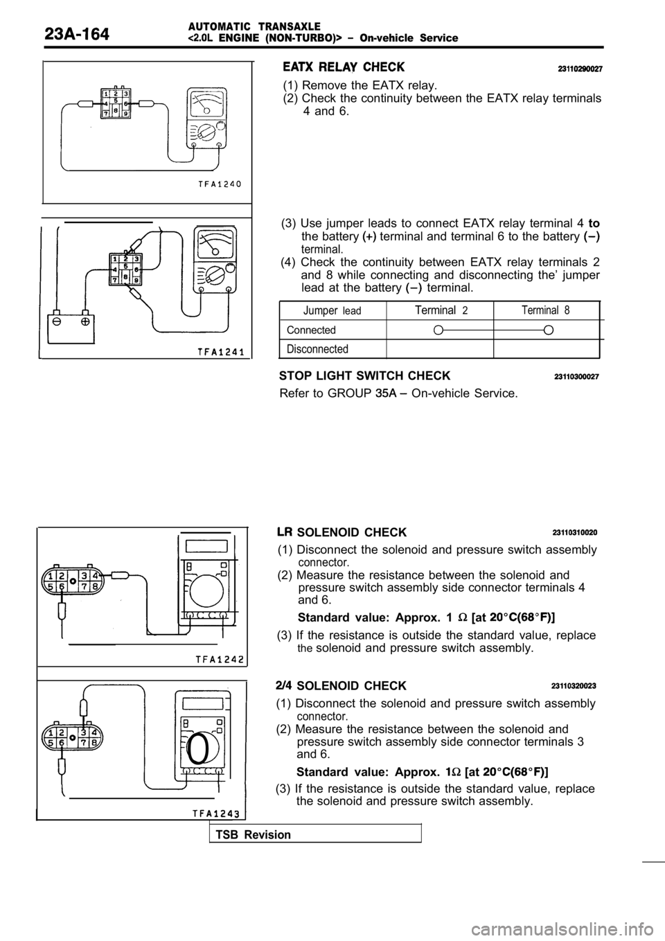
0
I
(1) Remove the EATX relay.
(2) Check the continuity between the EATX relay terminals
4 and 6.
(3) Use jumper leads to connect EATX relay terminal 4 to
the battery
terminal and terminal 6 to the battery
terminal.
(4) Check the continuity between EATX relay termina ls 2
and 8 while connecting and disconnecting the’ jumpe r
lead at the battery
terminal.
Jumperlead
Connected
Disconnected
Terminal2Terminal 8
STOP LIGHT SWITCH CHECK
Refer to GROUP
On-vehicle Service.
SOLENOID CHECK
(1) Disconnect the solenoid and pressure switch ass embly
connector.
(2) Measure the resistance between the solenoid and
pressure switch assembly side connector terminals 4
and 6.
Standard value: Approx. 1
[at
(3) If the resistance is outside the standard value , replace
the solenoid and pressure switch assembly.
SOLENOID CHECK
(1) Disconnect the solenoid and pressure switch ass embly
connector.
(2) Measure the resistance between the solenoid and
pressure switch assembly side connector terminals 3
and 6.
Standard value: Approx.
[at
(3) If the resistance is outside the standard value , replace
the solenoid and pressure switch assembly.
TSB Revision