Page 1122 of 2103
AUTOMATIC TRANSAXLE
ENGINE (TURBO) AND ENGINE> -‘Transaxle Oil Cooler
INSPECTION231
l Check the hose for cracks, damage
lCheck for rusted or clogged transaxle oil cooler.
l Check oil cooler fins for
damage, and clogged
with foreign matter.
TSB Revision
Page 1128 of 2103

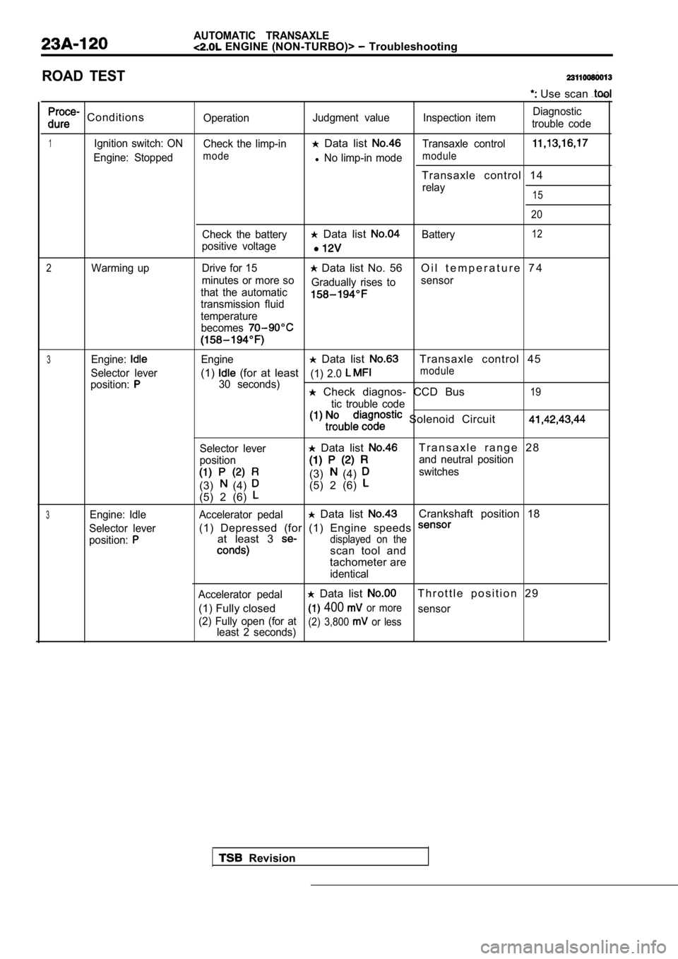
AUTOMATIC TRANSAXLE ENGINE (NON-TURBO)> Troubleshooting
ROAD TEST
Use scan
ConditionsOperationJudgment value Inspection item Diagnostic
trouble code
1Ignition switch: ON Check the limp-in Data list Transaxle control
Engine: Stoppedmodel No limp-in modemodule
Transaxle control 14
relay15
20
Check the battery Data list Battery12
positive voltage
2Warming up Drive for 15 Data list No. 56 O i l t e m p e r a t u r e 7 4
minutes or more so
that the automatic Gradually rises to
sensor
transmission fluid
temperature
becomes
3Engine:Engine Data list Transaxle control 45
Selector lever(1) (for at least(1) 2.0 module
position:30 seconds) Check diagnos- CCD Bus19
tic trouble code
Solenoid Circuit
Selector lever
position
(3) (4)
(5) 2 (6)
Data list T r a n s a x l e r a n g e 2 8
and neutral position
(3) (4) switches
(5) 2 (6)
3Engine: Idle Accelerator pedal Data list Crankshaft position 18
Selector lever(1) Depressed (for (1) Engine speeds
position:at least 3 displayed on the
scan tool and
tachometer are
identical
Accelerator pedal
Data list T h r o t t l e p o s i t i o n 2 9
(1) Fully closed
400 or moresensor
(2) Fully open (for at least 2 seconds)
(2) 3,800 or less
Revision
Page 1130 of 2103

AUTOMATIC TRANSAXLE
ENGINE (NON-TURBO)> Troubleshooting
dure
4Conditions
Selector lever
position:
lever
Operation
Engine
(1) Driving in
gea
with selector
in range
( 2 ) D r i v i n g i n
gear with lever in 2 range
(3) Driving in gea
with selector
in range
(OverdriveOFF)
(4) Driving in
gear with selec-
tor lever in
range(Overdriveswitch ON) (for at least 1
minute)
Driving in Re-
verse gear with
selector lever in
range (for at
least 30 se-
conds)
1) Driving in gear, then apply
the brake until a
downshift
occurs. (Do this
at least 3 times)
ingine
1) Driving atconstant speedof 80 km/h (50
mph) with selec-
tor lever in
range(Overdriveswitch ON)
Judgment value
Data list
and
(1) Check the UD
and clutch
(2)
the 2-4
(3)
the OD
clutch: 35 to 85
2-4 clutch: 20 to 77
OD clutch: 75 to
UD clutch: 24 to 70
Data list and
InputEngine
OutputInput
gear ratio
Data list
Data list
1) Locked gear
Inspection item
A T F l e v e l
UD hydraulic
circuit
2-4 and
clutch
Gear ratio in
gear
I n p u t a n d
speed sensor
Solenoidswitch
valve (latched in the
LU position)
Lockup control
Solenoid
switch
(latched in the
position)
Diagnostic
trouble
code
35
46
TSB Revision
36
36
56
57
58
37
38
47
Page 1132 of 2103
AUTOMATIC TRANSAXLE
ENGINE Troubleshooting
SERVICE DATA REFERENCE TABLE
Data No. Check itemDisplay
00 Throttle position sensor
01Transaxle range sensor 41
02Start or run position volt
03Transaxle range sensor 43
04 Switched battery volt
20 pressure switch
ON/OFF
212-4 pressureswitch
ON/OFF
22ODpressureswitch
ON/OFF
23 Overdrive lockout switch
ON/OFF
24Transaxle range sensor 1ON/OFF
25 Transaxle range sensor 2
ON/OFF
26Transaxle range sensor 43ON/OFF
27 Transaxle range sensor 41
ON/OFF
43 Engine speed
44Transaxle input speed
45Transaxle output speed
46Shift lever position information and controller lim
p-in status
Status
47Throttle position
48Transaxle shift schedule
Status
Partial/full lock status
58Shift code Status
59
60
61
Pressure switch error counter Counts
Speed/ratio error counter Counts
Speed/ratio error 1 second counter Counts
TSB Revision
Page 1133 of 2103
AUTOMATIC TRANSAXLE
ENGINE (NON-TURBO)> Troubleshooting
Data Check item
62Speed/ratio error 15 second counter
‘Display
Counts
63Engine model identification
64General flag
E n g i n e M o d e l
S t a t u s
65Actuator test statusIStatusI
66Element mask register StatusI
67
EEPROM flag register
68Output teeth count StatusTeeth
69Wheel speed coefficient in EEPROM
Coefficient
Current production MY/application MY Model Year
ACTUATOR R
E FER E N CE TA BL E
Item No.
Check item Drive contents Check conditions Remarks
01 solenoid
022-4 solenoid
03UD solenoid
04OD solenoid Current flows to the solenoid
Engine:Check the actuator
for 6 seconds at 50% duty. Idle (Vehicle stopped)test status (Display)
Selector lever position:
range
Throttle opening angle: Fully closed
Page 1134 of 2103

AUTOMATIC TRANSAXLE
ENGINE (NON-TURBO)> Troubleshooting
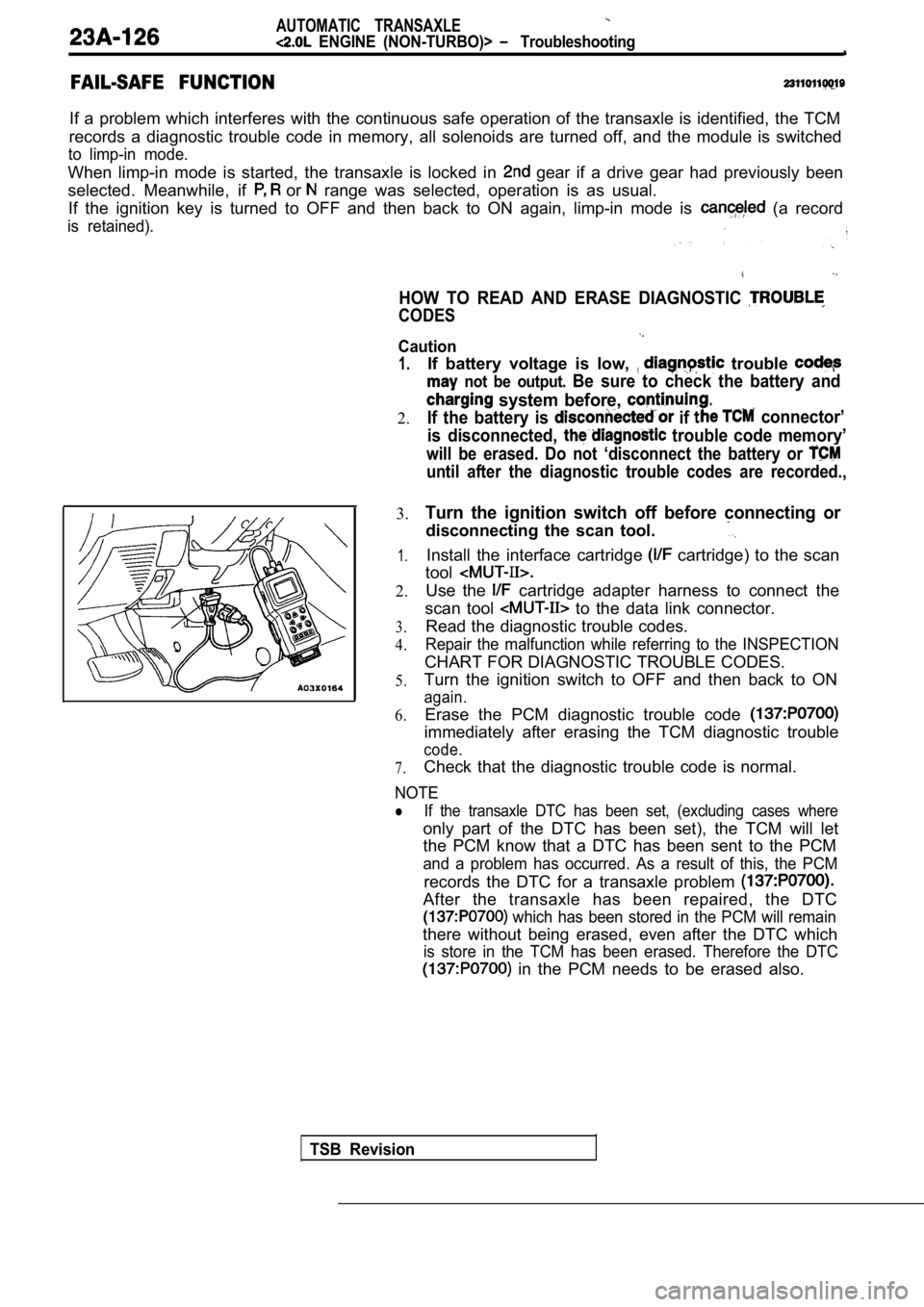
FAIL-SAFE FUNCTION
If a problem which interferes with the continuous safe operation of the transaxle is identified, the TCM
records a diagnostic trouble code in memory, all so lenoids are turned off, and the module is switched
to limp-in mode.
When limp-in mode is started, the transaxle is locked in gear if a drive gear had previously been
selected. Meanwhile, if
or range was selected, operation is as usual.
If the ignition key is turned to OFF and then back to ON again, limp-in mode is
(a record
is retained).
HOW TO READ AND ERASE DIAGNOSTIC
CODES
TSB Revision
1.
2.If battery voltage is low,
trouble
not be output. Be sure to check the battery and
system before, .
If the battery is if connector’
is disconnected,
trouble code memory’
will be erased. Do not ‘disconnect the battery or
until after the diagnostic trouble codes are record ed.,
3.
1.
2.
3.
4.
5.
6.
Turn the ignition switch off before connecting or
disconnecting the scan tool.
Install the interface cartridge cartridge) to the scan
tool
Use the cartridge adapter harness to connect the
scan tool
to the data link connector.
Read the diagnostic trouble codes.
Repair the malfunction while referring to the INSPE CTION
CHART FOR DIAGNOSTIC TROUBLE CODES.
Turn the ignition switch to OFF and then back to ON
again.
Erase the PCM diagnostic trouble code
immediately after erasing the TCM diagnostic troubl e
code.
7.Check that the diagnostic trouble code is normal.
Caution
NOTE
�If the transaxle DTC has been set, (excluding cases where
only part of the DTC has been set), the TCM will le t
the PCM know that a DTC has been sent to the PCM
and a problem has occurred. As a result of this, th e PCM
records the DTC for a transaxle problem
After the transaxle has been repaired, the DTC
which has been stored in the PCM will remain
there without being erased, even after the DTC whic h
is store in the TCM has been erased. Therefore the DTC
in the PCM needs to be erased also.
Page 1137 of 2103

AUTOMATIC TRANSAXLE
ENGINE (NON-TURBO)>
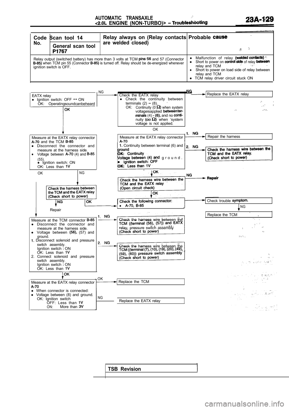
Code Scan tool 14Relay always on (Relay contacts Probable
No.General scan toolare welded closed)
Relay output (switched battery) has more than 3 vol
ts at TCM and 57 (Connectorl
Malfunction of relay when TCM pin 55 (Connector is turned off. Relay should be de-energized whenev erlShort to power on of relay relay and TCM.
ignition switch is OFF.
lShort to power on load side of relay between
relay and TCM
l TCM relay driver circuit stuck ON
EATX relay
l Ignition switch: OFF
ON
OK: Operatingsoundcanbeheard
Measure at the EATX relay connector and the TCM l Disconnect the connector and
measure at the harness side.
lVoltage between (4) and
(55).l Ignition switch: ON
OK: Less than
OKNG
I
NG
Measure at the EATX relay connectorRepair the harness
Continuity between terminal (6) and
2.
.
g r o u n d .
IRepair
Measure at the TCM connector
l Disconnect the connector and
measure at the harness side.
l Voltage between
(57) andground. Disconnect solenoid and pressureswitch assembly.Ignition switch ON
OK: Less than
2. Connect solenoid and pressureswitch assembly.Ignition switch ON
OK: Less than
Measure at the EATX relay connector
l When connector is connected:
l Voltage between (8) and ground.
OK: Ignition switch OFF: Less than
ON:More than
Check the EATX relay Replace the EATX relay
l Check the continuity between
terminals (2)
(8). .
OK: Continuity (0 when systemvoltageisapplied (4) and no nuity when ‘system
voltage is not applied.
OK
Check trouble
lNG
Check the harness wire between the
,
Replace the TCM
relay, pressure switch assembly
Check the harness wire between the
OK Replace the TCM
NGReplace the EATX relay
TSB Revision
Page 1138 of 2103

AUTOMATIC TRANSAXLE
ENGINE (NON-TURBO)> Troubleshooting.
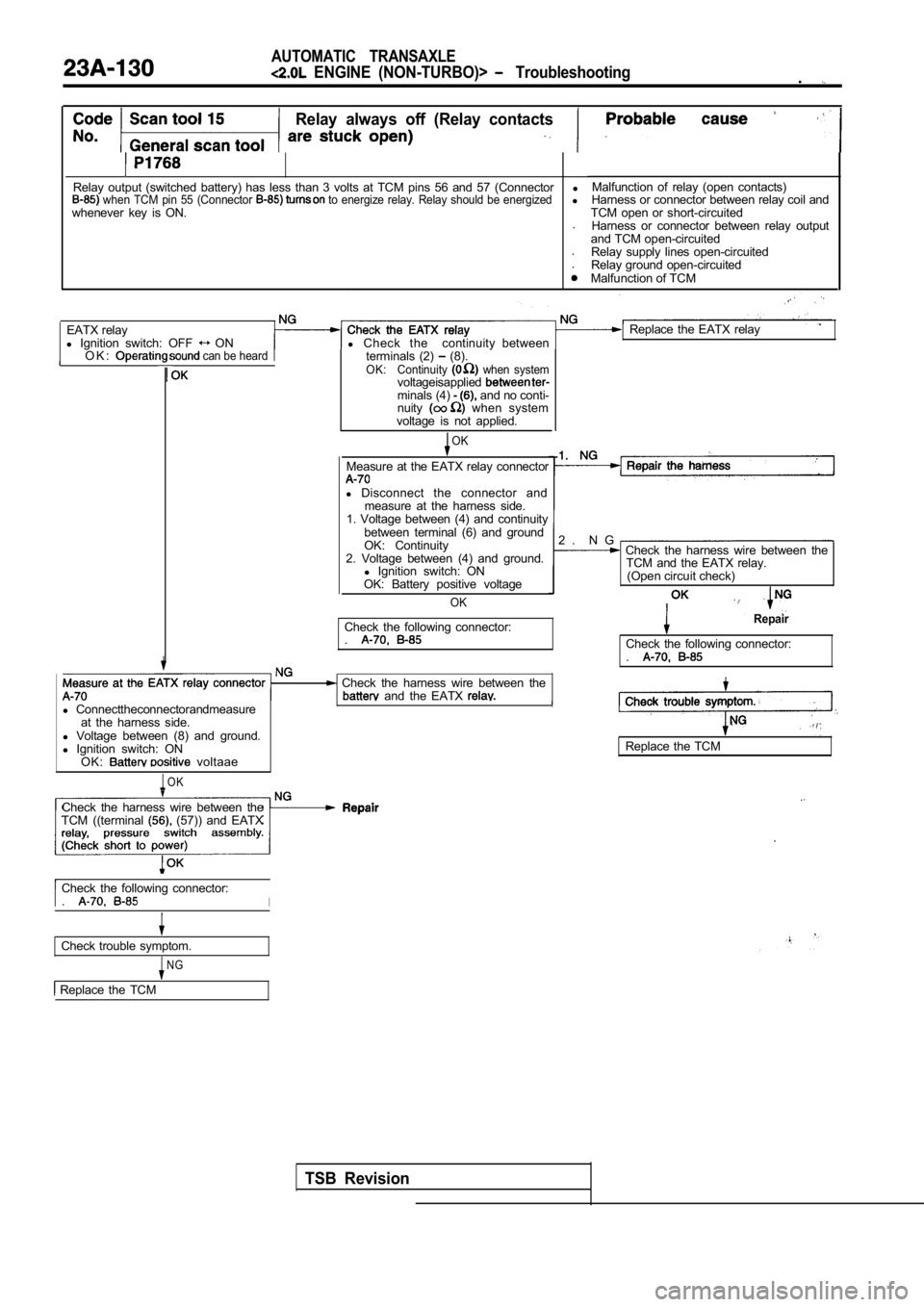
Relay always off (Relay contacts
Relay output (switched battery) has less than 3 volts at TCM pins 56 and 57 (Connectorl when TCM pin 55 (Connector to energize relay. Relay should be energizedl
whenever key is ON. .
. .Malfunction of relay (open contacts)
Harness or connector between relay coil and
TCM open or short-circuited Harness or connector between relay output
and TCM open-circuited Relay supply lines open-circuited
Relay ground open-circuited
Malfunction of TCM
EATX relay Replace the EATX relay
l Ignition switch: OFF
ON l Check thecontinuity between
O K : can be heardterminals (2) (8).OK: Continuity when systemvoltageisappliedminals (4) and no conti-
nuity when system
voltage is not applied.
OK
Measure at the EATX relay connector
l Disconnect the connector and
measure at the harness side.
1. Voltage between (4) and continuity
between terminal (6) and ground
OK: Continuity
2. Voltage between (4) and ground. l Ignition switch: ON
OK: Battery positive voltage
OK
2 . N G Check the harness wire between the TCM and the EATX relay.
(Open circuit check)
Check the following connector: .Repair
Check the following connector: .
l Connecttheconnectorandmeasure
at the harness side.
l Voltage between (8) and ground.
l Ignition switch: ON
OK:
voltaae
OK
Check the harness wire between the and the EATX
Replace the TCM
Check the harness wire between the
TCM ((terminal
(57)) and EATX
.
Check the following connector: .I
Check trouble symptom.
NG
Replace the TCM
TSB Revision