1990 MITSUBISHI SPYDER check engine
[x] Cancel search: check enginePage 1704 of 2103
6ABS
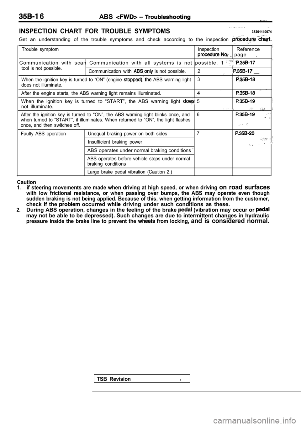
INSPECTION CHART FOR TROUBLE SYMPTOMS35201140074
Get an understanding of the trouble symptoms and check according to the inspection
Trouble symptom InspectionReference
p a g e
C o m m u n i c a t i o n w i t h s c a n C o m m u n i c a t i o n w i t h a l l s y s te m s i s n o t p o s s i b l e . 1
tool is not possible.
Communication with is not possible.2 __
When the ignition key is turned to “ON” (engine ABS warning light3
does not illuminate.
After the engine starts, the ABS warning light rema ins illuminated.
When the ignition key is turned to “START”, the ABS warning light 5
not illuminate.
After the ignition key is turned to “ON”, the ABS warning light blinks once, and6
when turned to “START”, it illuminates. When return ed to “ON”, the light flashes
once, and then switches off.
Faulty ABS operation Unequal braking power on both s ides7
Insufficient braking power
ABS operates under normal braking conditions
ABS operates before vehicle stops under normal
braking conditions
Large brake pedal vibration (Caution 2.)
Caution
1.if steering movements are made when driving at high speed, or when driving on road surfaces
with low frictional resistance, or when passing over bumps, the ABS may operate even though
sudden braking is not being applied. Because of thi s, when getting information from the customer,
check if the occurred driving under such conditions as these.
2.During ABS operation, changes in the feeling of the brake (vibration may occur or
may not be able to be depressed). Such changes are due to intermittent changes in hydraulic
pressure inside the brake line to prevent the from locking, and is considered normal.
TSB Revision,
Page 1706 of 2103
![MITSUBISHI SPYDER 1990 Service Repair Manual ABS Troubleshooting , ,
INSPECTION PROCEDURE 3When ignition key is turned to “ON” (engine stopped ),
ABS warning light does not illuminate
[Comment]When power is supplied to the MITSUBISHI SPYDER 1990 Service Repair Manual ABS Troubleshooting , ,
INSPECTION PROCEDURE 3When ignition key is turned to “ON” (engine stopped ),
ABS warning light does not illuminate
[Comment]When power is supplied to the](/manual-img/19/57345/w960_57345-1705.png)
ABS Troubleshooting , ,
INSPECTION PROCEDURE 3When ignition key is turned to “ON” (engine stopped ),
ABS warning light does not illuminate
[Comment]When power is supplied to the ABS-ECU, the valve relay changes from to ON by the initial check, and thus even if there is a problem with the circuit between
ABS light and ABS-ECU, the light will illuminate once when the valve relay
is OFF.
Accordingly, the cause of the light not illuminatin g is probably an open circuit in the
light power circuit, a blown light bulb, or an open circuit in both the circuit between
the ABS
light and the ABS-ECU and the circuit between the ABS light and the ABS valve relay.When other lights also do not illuminate, the cause is probably a blown fuse.
Measure at combination meter connector
l Disconnect the connector and mea-
sure at the harness side.
l Ignition Switch ON
lVoltage between terminal 10 and body
OK Battery positive voltage Check trouble symptoms
Measure at combination meter connector
sure at the combination meter side.
l Continuitv between terminals
R e p l a c e t h e
OK Continuity ,
OK
Check the harnesses between the ABS valve relay and the combination meter,
a n d b e t w e e n t h e A B S - E C U a n d
combination meter (common section).
if necessary.
INSPECTION PROCEDURE 4
TSB Revision.
Even after the engine is started, the ABS Warning l ight ,remains illuminated.. .
[Comment]There is probably a short in the ABS warning light illumination circuit.l Malfunction of combination meterl Malfunction of ABS valve relayl Malfunction of ABS-ECU. ,
NOTE
This trouble symptom is limited to cases where comm unication with the scan tool is’
is normal) and the diagnostic trouble code is a normal diagnostic trouble code..YESDisconnect the ABS-ECU connector Does the light remain illuminated?
NO
Short circuit inside the combination or in the harnessbetween the meter and
Replace the ABS-ECU.
Page 1710 of 2103
ABS Troubleshooting. ,
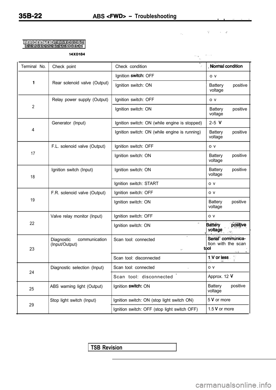
Terminal No.Check pointCheck condition,
Ignition OFFo v
Rear solenoid valve (Output)
Ignition switch: ON Batterypositive
voltage
Relay power supply (Output) Ignition switch: OFF
o v
2Ignition switch: ON Battery positive voltage
Generator (Input) Ignition switch: ON (while engine is stopped)
2-5
4Ignition switch: ON (while engine is running) Battery positive
voltage
17
F.L. solenoid valve (Output) Ignition switch: OFF
Ignition switch: ONo v
Batterypositive
voltage
18
19
Ignition switch (Input)
F.R. solenoid valve (Output) Ignition switch: ON
Ignition switch: START
Ignition switch: OFF
Ignition switch: ON Battery
voltage
o v
o v
Battery
voltage positive
positive
22
23 Valve relay monitor (Input)
Ignition switch: OFF
o v
Ignition switch: ON
,
Diagnosticcommunication
Scan tool: connected
(Input/Output)tion with the scan
24
Diagnostic selection (Input) Scan tool: disconnectedScan tool: connectedo v
S c a n t o o l : d i s c o n n e c t e d
Approx. 12
25ABS warning light (Output) Ignition ON Battery
voltage positive
29
Stop light switch (Input)
Ignition switch: ON (stop light switch ON) 5 or more
Ignition switch: OFF (stop light switch OFF) 1.5
or more
TSB Revision
Page 1713 of 2103
Service
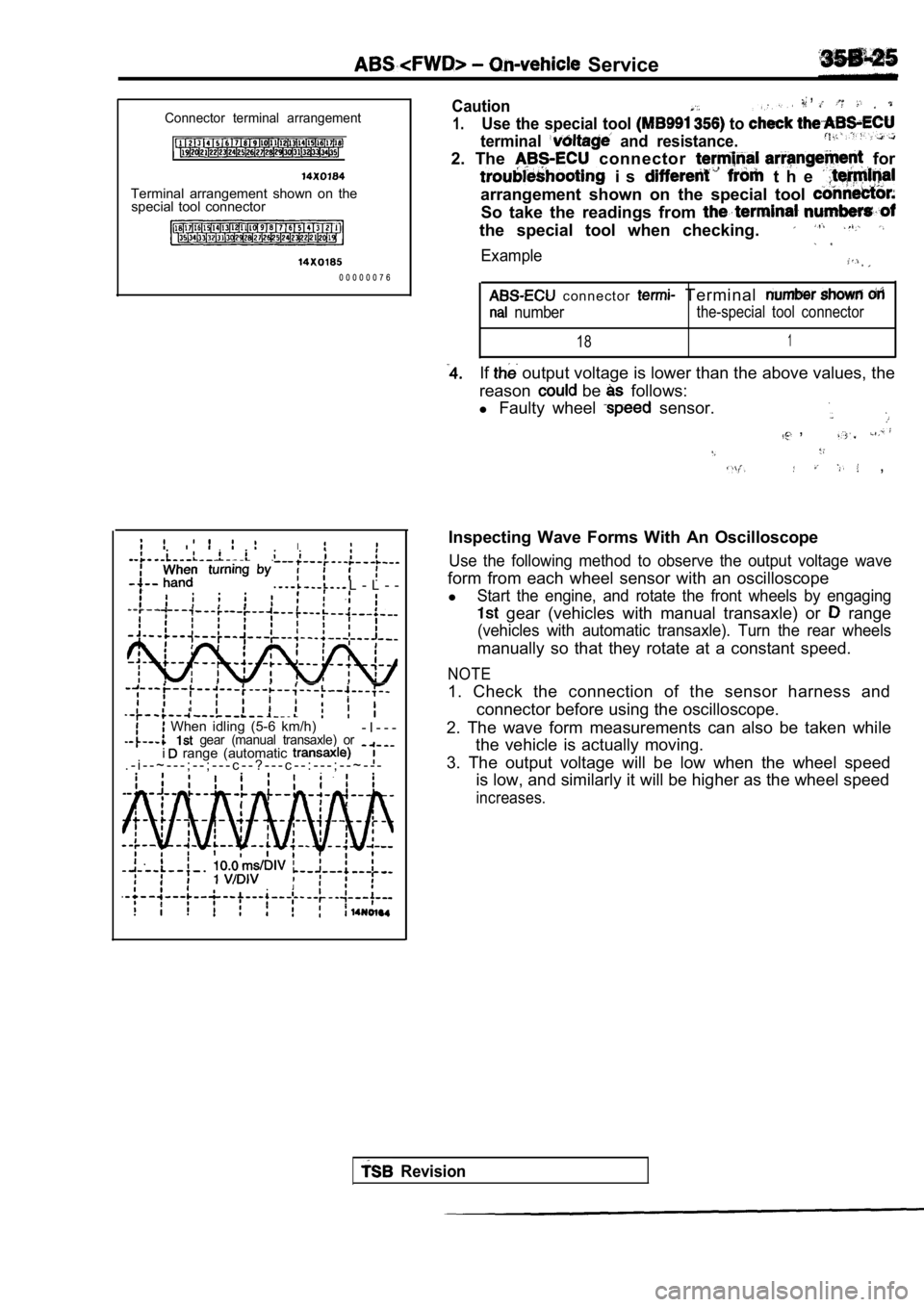
Connector terminal arrangement
Terminal arrangement shown on thespecial tool connector
0 0 0 0 0 0 7 6
L - L - -
,
I
When idling (5-6 km/h) gear (manual transaxle) or- I - - -
. - i - - ~ - - - ; - - ; - - - c - - ? - - - c - - : - - - ; - - ~ - - - i range (automatic
,Caution,
1.Use the special tool to
terminal and resistance.
2. The connector for
i s t h e
arrangement shown on the special tool
So take the readings from
the special tool when checking.
Example
c o n n e c t o r Terminal
numberthe-special tool connector
181
If output voltage is lower than the above values, the
reason
be follows:
l Faulty wheel
sensor.
,
,
Inspecting Wave Forms With An Oscilloscope
Use the following method to observe the output volt age wave
form from each wheel sensor with an oscilloscope
l
Start the engine, and rotate the front wheels by en gaging
gear (vehicles with manual transaxle) or range
(vehicles with automatic transaxle). Turn the rear wheels
manually so that they rotate at a constant speed.
NOTE
1. Check the connection of the sensor harness and
connector before using the oscilloscope.
2. The wave form measurements can also be taken whi le
the vehicle is actually moving.
3. The output voltage will be low when the wheel sp eed
is low, and similarly it will be higher as the whee l speed
increases.
Revision
Page 1715 of 2103
A B S
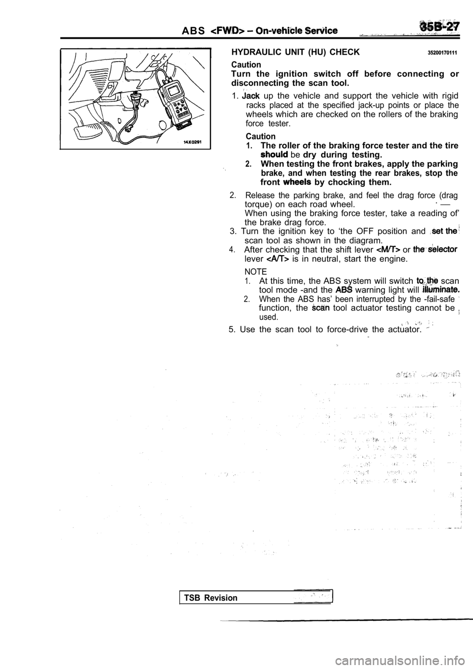
HYDRAULIC UNIT (HU) CHECK
Caution
35200170111
Turn the ignition switch off before connecting ordisconnecting the scan tool.
1.
up the vehicle and support the vehicle with rigid
racks placed at the specified jack-up points or pla ce the
wheels which are checked on the rollers of the brak ing
force tester.
Caution
1.The roller of the braking force tester and the tire
be dry during testing.
2.When testing the front brakes, apply the parking
brake, and when testing the rear brakes, stop the
front by chocking them.
2.Release the parking brake, and feel the drag force (drag
torque) on each road wheel.. __
When using the braking force tester, take a reading of’
the brake drag force.
3. Turn the ignition key to ‘the OFF position and
scan tool as shown in the diagram.
4.After checking that the shift lever or
lever is in neutral, start the engine.
NOTE
1.At this time, the ABS system will switch scan
tool mode -and the
warning light will
2.When the ABS has’ been interrupted by the -fail-saf e
function, the tool actuator testing cannot be
used.
5. Use the scan tool to force-drive the actuator.
TSB Revision
Page 1719 of 2103
ABSOn-vehicle Service
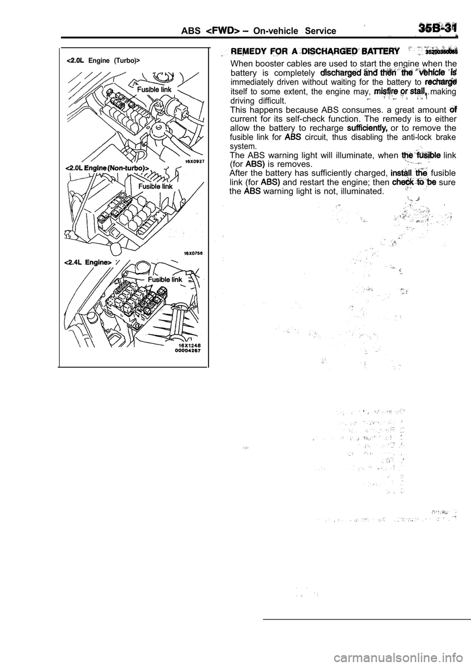
Engine (Turbo)>When booster cables are used to start the engine when the
battery is completely
immediately driven without waiting for the battery to
itself to some extent, the engine may, making
driving difficult. 1’
This happens because ABS consumes. a great amount
current for its self-check function. The remedy is to either
allow the battery to recharge
or to remove the
fusible link for circuit, thus disabling the anti-lock brake
system.
The ABS warning light will illuminate, when link
(for
is removes.
After the battery has sufficiently charged, fusible
link (for
and restart the engine; then sure
the
warning light is not, illuminated.
Page 1743 of 2103
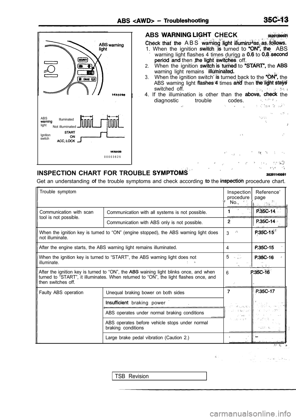
ABS CHECK
A B S
1. When the ignition turned to ABS
warning light flashes 4 times during a to
then off.
2.When the ignition to the
warning light remains
3.When the ignition switch’ turned back to the the
ABS warning light times then
switched off. ,
4. If the illumination is other than the the
diagnostic trouble codes.
ABSIlluminated
light
Not illuminated
Ignition
switch
0 0 0 0 3 6 2 5
INSPECTION CHART FOR TROUBLE
Get an understanding the trouble symptoms and check according the procedure chart.
Trouble symptom
Communication with scan
tool is not possible.Inspection Reference’
procedure
page No.,
Communication with all systems is not possible.
Communication with ABS only is not possible.
When the ignition key is turned to “ON” (engine sto pped), the ABS warning light does
3not illuminate.
After the engine starts, the ABS warning light rema ins illuminated.
4
When the ignition key is turned to “START”, the ABS warning light does not5
illuminate.
After the ignition key is turned to “ON”, the waining light blinks once, and when6turned to “START”, it illuminates. When returned to “ON”, the light flashes once, and
then switches off.
Faulty ABS operation Unequal braking bower on both sides
. braking power
ABS operates under normal braking conditions
ABS operates before vehicle stops under normal braking conditions
Large brake pedal vibration (Caution 2.)
TSB Revision
Page 1745 of 2103
![MITSUBISHI SPYDER 1990 Service Repair Manual ABS Troubleshooting
INSPECTION PROCEDURE 3
ignition key is turned to “ON’? (engine stopped),ProbableABS warning light does not illuminate
[Comment]When power is supplied to the ABS- MITSUBISHI SPYDER 1990 Service Repair Manual ABS Troubleshooting
INSPECTION PROCEDURE 3
ignition key is turned to “ON’? (engine stopped),ProbableABS warning light does not illuminate
[Comment]When power is supplied to the ABS-](/manual-img/19/57345/w960_57345-1744.png)
ABS Troubleshooting
INSPECTION PROCEDURE 3
ignition key is turned to “ON’? (engine stopped),ProbableABS warning light does not illuminate
[Comment]When power is supplied to the ABS-ECU, the valve relay changes from to OFF ON by the initial check, and thus even if there is a problem with the circuit betweenABS warning light and ABS-ECU, the light will illum inate once when the valve relayis OFF.Accordingly, the cause of the light not illuminating is probably an open circuit in the
light power circuit, a blown light bulb, or an open circuit in both the circuit between
the ABS
liaht and the ABS-ECU and the circuit between the ABS
l Blown fuselBurntout light. bulblMalfunction of wiring. or connector
.
light and the relay.When other lights also do not illuminate, the cause is probab ly a blown fuse.
N GNG ,
Measure at combination meter connector Checkl and l Disconnect the connector and mea-
l Disconnect the connector and mea-
sure atthe combination meter side.
l Continuitv between terminals
OK Continuity
OK
Not
Replace combination meter.
, Check the harnesses between the valve relay and the combination meter,
a n d b e t w e e n t h e A B S - E C U a n d
combination meter (common section).
Repair, if necessary.
INSPECTION PROCEDURE 4
Even after the engine is started, the ABS warning l ight Probable cause ,
remains illuminated.
[Comment]There is probably a short in the ABS light illumination l Malfunction of meter
l Malfunction of valve relay
l Malfunction of ABS-ECU
l Malfunction of wiring
NOTE
This trouble symptom is limited to cases where comm unication with the scan tool is
supply is normal) and the diagnostic trouble code is a normal diagnostic trouble code.
Disconnect the ABS-ECU connector Short circuit inside the combination meter or in the Does the ABS warning light remain illuminated? between the combination meter and the ABS-ECU.
NO
Replace the ABS-ECU.
TSB Revision