1990 MITSUBISHI SPYDER check engine
[x] Cancel search: check enginePage 1818 of 2103

S T E E R I N G ower Steering Oil Pump Engine (Turbo) and Engine>
INSPECTION
l Check the flow control valve for
Check the pulley assembly for wear or damage.
l Check the groove of rotor and vane for “stepped” we ar.
l Check the contact surface of cam ring and vanes for
“stepped” wear.
l Check the vanes for damage.
TSB Revision
Page 1986 of 2103
INTERIOR Front Seat Belt
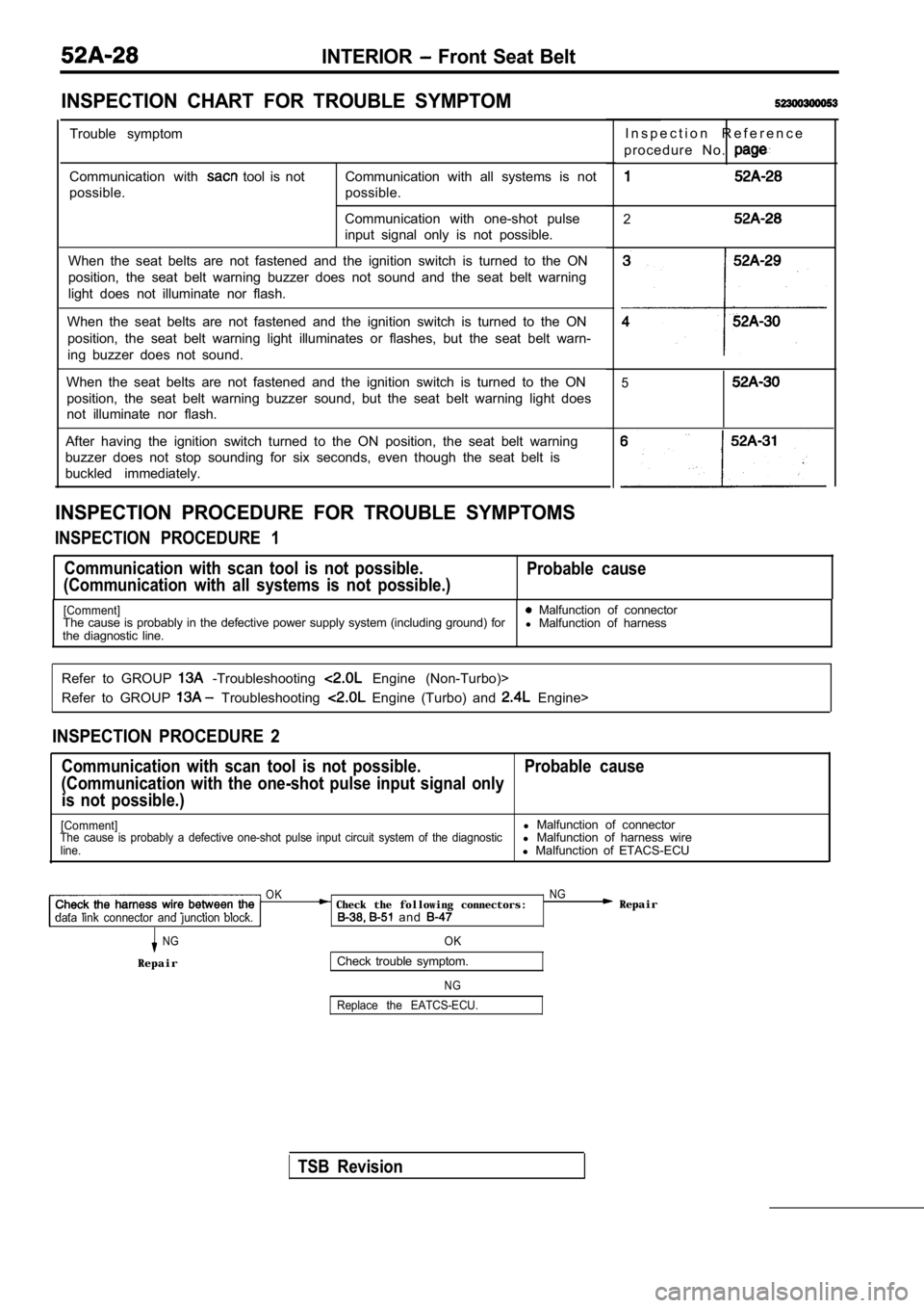
INSPECTION CHART FOR TROUBLE SYMPTOM
Trouble symptom
Communication with
tool is not
possible. Communication with all systems is not
possible.
Communication with one-shot pulse
input signal only is not possible.
When the seat belts are not fastened and the igniti on switch is turned to the ON
position, the seat belt warning buzzer does not sou nd and the seat belt warning
light does not illuminate nor flash.
When the seat belts are not fastened and the igniti on switch is turned to the ON
position, the seat belt warning light illuminates o r flashes, but the seat belt warn-
ing buzzer does not sound.
When the seat belts are not fastened and the igniti on switch is turned to the ON
position, the seat belt warning buzzer sound, but t he seat belt warning light does
not illuminate nor flash.
After having the ignition switch turned to the ON p osition, the seat belt warning
buzzer does not stop sounding for six seconds, even though the seat belt is
buckled immediately.
INSPECTION PROCEDURE FOR TROUBLE SYMPTOMS
INSPECTION PROCEDURE 1
I n s p e c t i o n R e f e r e n c e
p r o c e d u r e N o .
2
3
4
5
Communication with scan tool is not possible.
(Communication with all systems is not possible.) Probable cause
[Comment] Malfunction of connector
The cause is probably in the defective power supply system (including ground) for
l Malfunction of harness
the diagnostic line.
Refer to GROUP
-Troubleshooting Engine (Non-Turbo)>
Refer to GROUP
Troubleshooting Engine (Turbo) and Engine>
INSPECTION PROCEDURE 2
Communication with scan tool is not possible. Probab le cause
(Communication with the one-shot pulse input signal only
is not possible.)
[Comment]l Malfunction of connectorThe cause is probably a defective one-shot pulse in put circuit system of the diagnosticl Malfunction of harness wireline.l Malfunction of ETACS-ECU
OK NG Check the following connectors: Repairdata link connector and junction block. and
NGOK
RepairCheck trouble symptom.
N G
Replace the EATCS-ECU.
TSB Revision
Page 2041 of 2103
CONTENTS
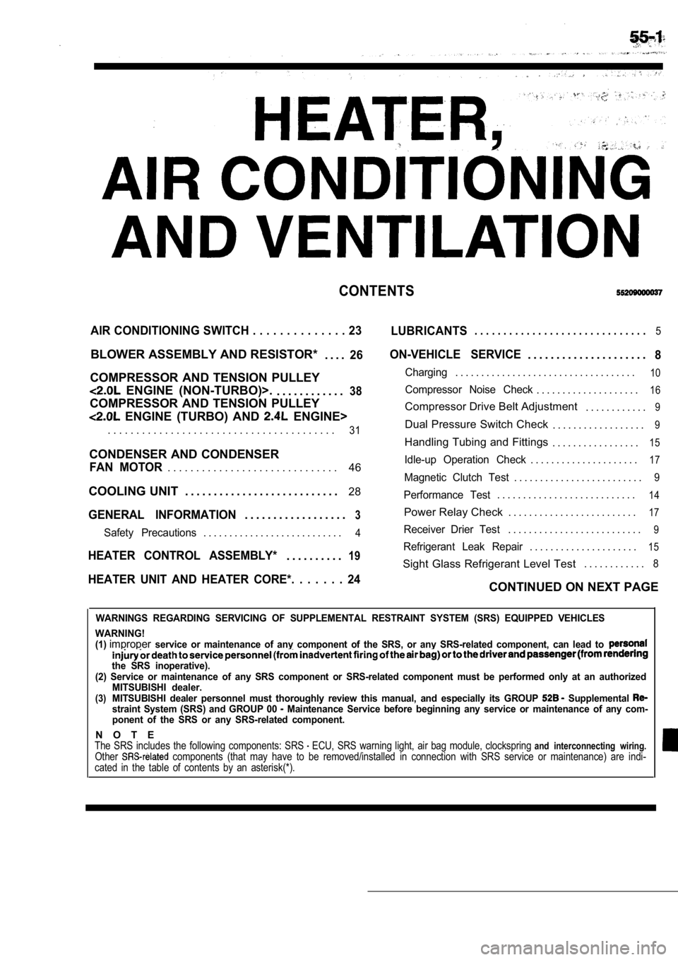
AIR CONDITIONING SWITCH . . . . . . . . . . . . . . 23
LUBRICANTS. . . . . . . . . . . . . . . . . . . . . . . . . . . . . .5
BLOWER ASSEMBLY AND RESISTOR*
. . . .26
COMPRESSOR AND TENSION PULLEY
ENGINE (NON-TURBO)>.. . . . . . . . . . . .38
COMPRESSOR AND TENSION PULLEY
ENGINE (TURBO) AND ENGINE>
ON-VEHICLE SERVICE. . . . . . . . . . . . . . . . . . . . .8
Charging. . . . . . . . . . . . . . . . . . . . . . . . . . . . . . . . . . .10
Compressor Noise Check. . . . . . . . . . . . . . . . . . . .16
Compressor Drive Belt Adjustment . . . . . . . . . . . .9
. . . . . . . . . . . . . . . . . . . . . . . . . . . . . . . . . . . . . . . .31Dual Pressure Switch Check. . . . . . . . . . . . . . . . . .9
Handling Tubing and Fittings. . . . . . . . . . . . . . . . .15
CONDENSER AND CONDENSER
46Idle-up Operation Check. . . . . . . . . . . . . . . . . . . . .17FAN MOTOR. . . . . . . . . . . . . . . . . . . . . . . . . . . . . .Magnetic Clutch Test. . . . . . . . . . . . . . . . . . . . . . . . .9
COOLING UNIT . . . . . . . . . . . . . . . . . . . . . . . . . . . 28
GENERAL INFORMATION3. . . . . . . . . . . . . . . . . .
Performance Test. . . . . . . . . . . . . . . . . . . . . . . . . . .14
Power Relay Check . . . . . . . . . . . . . . . . . . . . . . . . .17
Safety Precautions. . . . . . . . . . . . . . . . . . . . . . . . . . .4Receiver Drier Test. . . . . . . . . . . . . . . . . . . . . . . . . .9
. . . . . . . . . . . . . . . . . . . . .15HEATER CONTROL ASSEMBLY*19Refrigerant Leak Repair. . . . . . . . . .
Sight Glass Refrigerant Level Test . . . . . . . . . . . .8
HEATER UNIT AND HEATER CORE*. . . . . . . 24CONTINUED ON NEXT PAGE
WARNINGS REGARDING SERVICING OF SUPPLEMENTAL RESTRA
INT SYSTEM (SRS) EQUIPPED VEHICLES
WARNING!
(1)
improperservice or maintenance of any component of the SRS, or any SRS-related component, can lead to
the SRS inoperative).
(2) Service or maintenance of any SRS component or SRS-related component must be performed only at an authorized
MITSUBISHI dealer.
(3)MITSUBISHI dealer personnel must thoroughly review this manual, and especially its GROUP Supplemental straint System (SRS) and GROUP 00 Maintenance Service before beginning any service or maintenance of any com-
ponent of the SRS or any SRS-related component.
N O T EThe SRS includes the following components: SRS ECU, SRS warning light, air bag module, clocksprin g and interconnecting wiring.Other components (that may have to be removed/installed in connection with SRS service or maintenance) are indi-
cated in the table of contents by an asterisk(*).
Page 2047 of 2103

HEATER, AIR
AND VENTILATION Troubleshooting
Trouble
symptomProblem cause
Remedy
ReferencepageEngine Engine’
(Non-turbo)(Turbo) and Engine
When the A/C isRefrigerant leak
Replenish the refrigerant and 0o p e r a t i n g , t e r n -pair the leakperature inside
the passengerDual pressure switch is Replace the dual pressure switch55-45
compartmenttive
(no cool air).Fin sensor is defective
Replace the fin sensor
Refrigerant temperature switch Replace the refriger ant tempera-
is defective Engine (Tur-
ture switch
bo) and
Engine>
Automatic compressor-ECM Replace the automatic
55-26is defectivesor-ECM
Blower-motor/fan Blower moter relay is
Replace the blower moter relay55-1755-17inoperativetive
Blower fan and motor is Replace the blower fan and motor55-26
Resistor (for blower motor) is
Replace the resistor55-26
defective
Blower switch is defective Replace the blower switch
55-2255-22
Blower fan and Short circuit of the harness Repair the harness
motor keeps
between the blower fan and
ningmotor and the blower switch
Blower switch is defective Replace the blower switch
55-2255-22
Blower relay is defective
Replace the blower moter relay 55-1755-17
the A/C is Condenser fan motor is Replace the condenser fan motor55-47 55-46
fan Condenser fan relay (LO) is
Replace the condenser fan relay 55-18
defective
Condenser fan relay (HI) is Replace the condenser fa n relay55-1855-18
defective
INSPECTION AT THE AUTOMATIC COMPRESSOR-ECM TERMINAL
Engine (Turbo) and Engine>
Terminal No.Name of Signal Check requirementsTerminal voltage
1Automatic compressor-ECM power The ignition switch, blower switch Battery positive
supply (output side) and A/C switch are all ON
v o l t a g e
2Automatic compressor-ECM power
supply (input side)
The ignition switch,
and switch are all ON Batteryvoltage
3A u t o m a t i c c o m p r e s s o r - E C M g r o u n d o v
TSB Revision
Page 2048 of 2103
55-8HEATER, AIR
AND VENTILATION Troubleshooting/On-vehicle Service
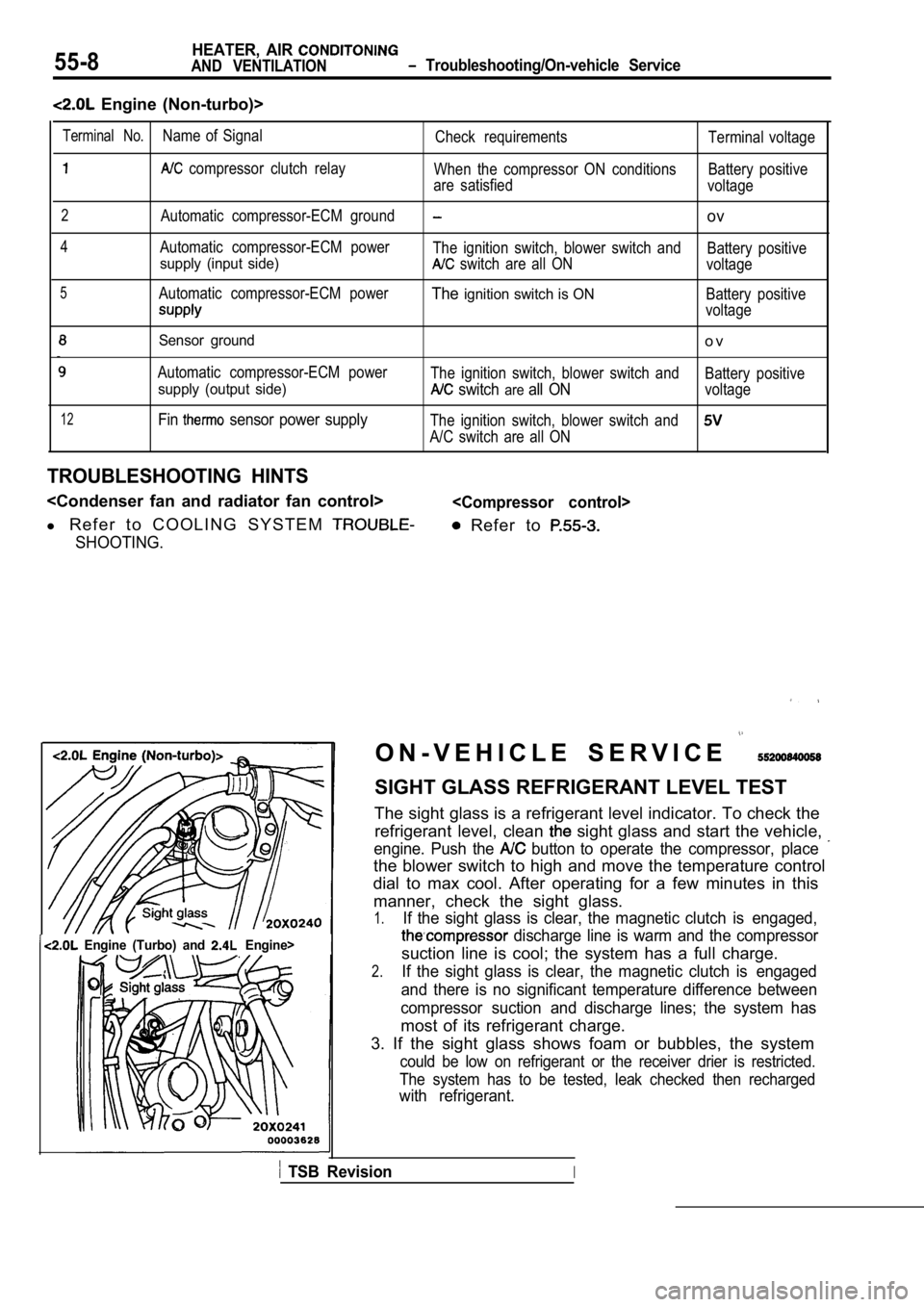
Engine (Non-turbo)>
12
Sensor ground
Automatic compressor-ECM power
supply (output side)
Fin sensor power supply
o v
The ignition switch, blower switch andBattery positive
switch areall ONvoltage
The ignition switch, blower switch and
A/C switch are all ON
TROUBLESHOOTING HINTS
l R e f e r t o C O O L I N G S Y S T E M
SHOOTING.
Refer to
Terminal No.Name of Signal
Check requirements Terminal voltage
compressor clutch relay
When the compressor ON conditions Battery positive
are satisfied voltage
2Automatic compressor-ECM groundov
4Automatic compressor-ECM power
The ignition switch, blower switch and Battery positive
supply (input side) switch are all ONvoltage
5Automatic compressor-ECM powerTheignition switch is ONBattery positive
voltage
Engine (Turbo) and Engine>I
O N - V E H I C L E S E R V I C E
SIGHT GLASS REFRIGERANT LEVEL TEST
The sight glass is a refrigerant level indicator. T o check the
refrigerant level, clean
sight glass and start the vehicle,
engine. Push the button to operate the compressor, place
the blower switch to high and move the temperature control
dial to max cool. After operating for a few minutes in this
manner, check the sight glass.
1.If the sight glass is clear, the magnetic clutch is engaged,
discharge line is warm and the compressor
suction line is cool; the system has a full charge.
2.If the sight glass is clear, the magnetic clutch is engaged
and there is no significant temperature difference between
compressor suction and discharge lines; the system has
most of its refrigerant charge.
3. If the sight glass shows foam or bubbles, the sy stem
could be low on refrigerant or the receiver drier is restricted.
The system has to be tested, leak checked then rech arged
with refrigerant.
TSB RevisionI
Page 2051 of 2103
HEATER, AIR
AND VENTILATION On-vehicle
Bulk
Adaptorvalve
Bulk[Refrigerant container)
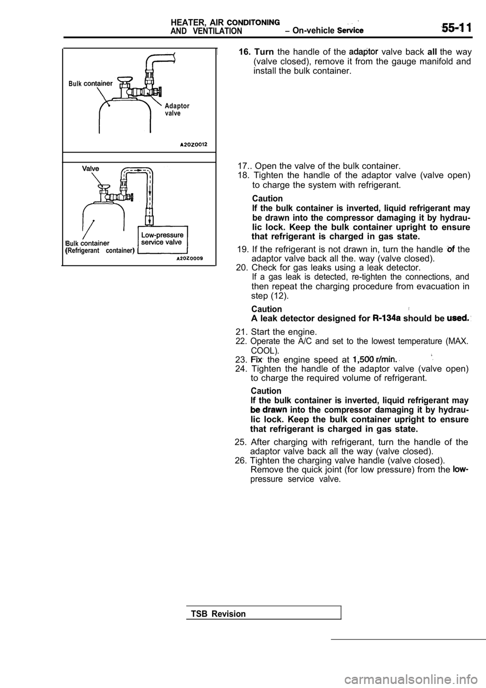
16. Turn the handle of the valve back allthe way
(valve closed), remove it from the gauge manifold a nd
install the bulk container.
17.. Open the valve of the bulk container.
18. Tighten the handle of the adaptor valve (valve open)
to charge the system with refrigerant.
Caution
If the bulk container is inverted, liquid refrigera nt may
be drawn into the compressor damaging it by hydrau-
lic lock. Keep the bulk container upright to ensure
that refrigerant is charged in gas state.
19. If the refrigerant is not drawn in, turn the ha ndle
the
adaptor valve back all the. way (valve closed).
20. Check for gas leaks using a leak detector.
If a gas leak is detected, re-tighten the connectio ns, and
then repeat the charging procedure from evacuation in
step (12).
Caution
A leak detector designed for should be
21. Start the engine.
22. Operate the A/C and set to the lowest temperatu re (MAX.
COOL).
23. the engine speed at
24. Tighten the handle of the adaptor valve (valve open)
to charge the required volume of refrigerant.
Caution
If the bulk container is inverted, liquid refrigera nt may
into the compressor damaging it by hydrau-
lic lock. Keep the bulk container upright to ensure
that refrigerant is charged in gas state.
25. After charging with refrigerant, turn the handl e of the
adaptor valve back all the way (valve closed).
26. Tighten the charging valve handle (valve closed ).
Remove the quick joint (for low pressure) from the
pressure service valve.
TSB Revision
Page 2052 of 2103
HEATER, AIR
AND VENTILATION On-vehicle Service
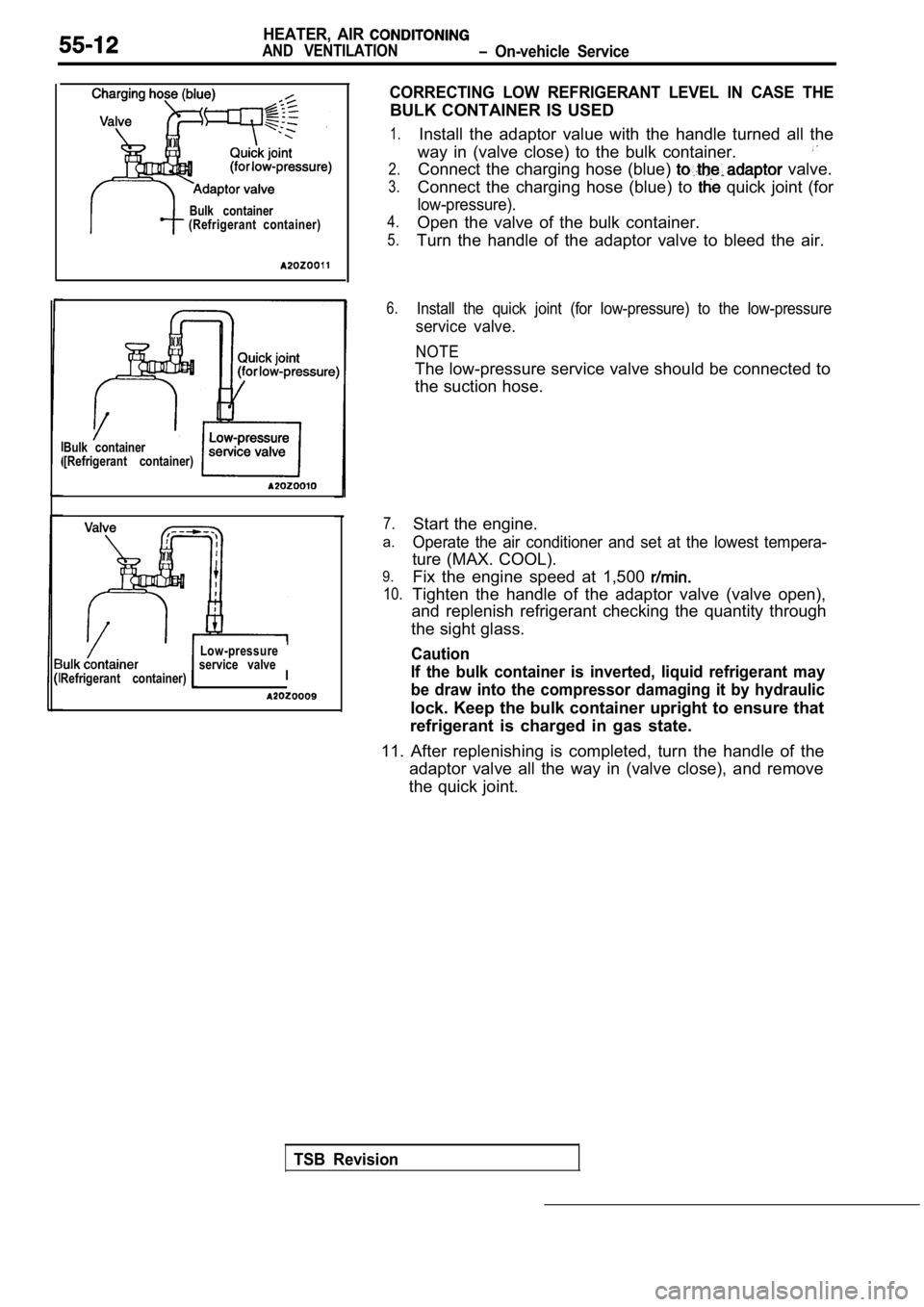
Bulk container
[Refrigerant container)
Refrigerant container)Bulk container
(Refrigerant container)
Low-pressure
service valve
I
CORRECTING LOW REFRIGERANT LEVEL IN CASE THE
BULK CONTAINER IS USED
1.
2.
3.
4.
5.
Install the adaptor value with the handle turned al l the
way in (valve close) to the bulk container.
Connect the charging hose (blue) valve.
Connect the charging hose (blue) to
quick joint (for
low-pressure).
Open the valve of the bulk container.
Turn the handle of the adaptor valve to bleed the a ir.
6.Install the quick joint (for low-pressure) to the low-pressure
service valve.
NOTE
The low-pressure service valve should be connected to
the suction hose.
7.
a.
9.
10.
Start the engine.
Operate the air conditioner and set at the lowest t empera-
ture (MAX. COOL).
Fix the engine speed at 1,500
Tighten the handle of the adaptor valve (valve open ),
and replenish refrigerant checking the quantity thr ough
the sight glass.
Caution
If the bulk container is inverted, liquid refrigera nt may
be draw into the compressor damaging it by hydrauli c
lock. Keep the bulk container upright to ensure that
refrigerant is charged in gas state.
11. After replenishing is completed, turn the handl e of the
adaptor valve all the way in (valve close), and rem ove
the quick joint.
TSB Revision
Page 2056 of 2103
6HEATER, AIR
AND VENTILATION On-vehicle Service
COMPRESSOR NOISE CHECK
You must first know the conditions when the noise occurs. These conditions are: weather, vehicle speed,
in gear or neutral, engine temperature or any other special conditions.
Noises that develop during A/C operation can often be misleading. For example: what sounds like a
failed front bearing or connecting rod, may be caus ed by loose bolts, nuts, mounting brackets, or a
loose clutch assembly. Verify accessory drive belt tension (power steering or generator).
Improper accessory drive belt tension can cause a m isleading noise when the compressor is engaged
and little or no noise when the compressor is disen gaged.
Drive belts are speed-sensitive. That is, at differ ent engine speeds, and depending upon belt tension,
belts can develop unusual noises that are often mis taken for mechanical problems within the compressor .
ADJUSTMENT
1. Select a quiet area for testing. Duplicate conditions as much as possible. Switch compressor on
and off several times to clearly identify compresso r noise. To duplicate high ambient
head pressure), restrict air flow through condenser . Install manifold gauge set sure discharge
pressure doesn’t exceed 2,070 (300 psi).
2. Tighten all compressor mounting bolts, clutch mo unting bolt, and compressor drive belt. Check to
assure clutch coil is tight (no rotation or wobble) .
3. Check refrigerant hoses for rubbing or interfere nce that can cause unusual noises.
4. Check refrigerant charge. (Refer to
5. Recheck compressor noise as in Step 1.
6. If noise still exists, loosen compressor mountin g bolts and retorque. Repeat Step 1.
7. If noise continues, replace compressor and repea t Step 1.
Revision