Page 2057 of 2103

HEATER, AIR
AND VENTILATION On-vehicle Service
IDLE-UP OPERATION CHECK
1,Before inspection and adjustment, set the f&w-
ing condition:
lEngine coolant temperature:
lLights, electric cooling fan and accessories: Set t o
OFF
lTransmission: Neutral (N or for vehicles with
l Steering wheel:
2. Check whether or not the idling speed is the sta ndard
value.
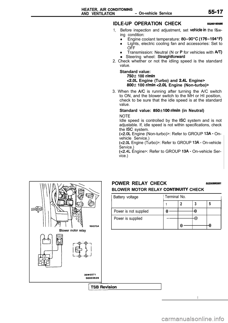
Blower relay
Standard value:
100
Engine (Turbo) and Engine>
100 Engine (Non-turbo)>
3. When the
is running after turning the A/C switch
to ON, and the blower switch to the MH or HI positi on,
check to be sure that the idle speed is at the stan dard
value.
Standard value: (in Neutral)
NOTE
Idle speed is controlled by the system and is not
adjustable. If, idle speed is not within specifications, check
the system.
Engine (Non-turbo)>: Refer to GROUP On-
vehicle Service.)
Engine (Turbo)>: Refer to GROUP On-vehicle
Service.)
Engine>: Refer to GROUP On-vehicle Ser-
vice.)
POWER RELAY CHECK
BLOWER MOTOR RELAY CHECK
Battery voltage Terminal No.III
1235
Power is not supplied
Power is supplied0 0
0 0
Page 2058 of 2103
Engine (Turbo)>HEATER,
AIRAND VENTILATION On-vehicle Service
A/C COMPRESSOR CLUTCH RELAY, CONDENSER FAN
RELAY (LO) AND (HI) CONTINUITY CHECK
Batteryvoltage Terminal No.
13 45
Power is not supplied0
Engine (Non-turbo)>
Condenser
fan relay (LO)
Engine>
NC
clutch relay
ment relay box
Power is supplied0
TSB Revision
Page 2070 of 2103
HEATER, AIR
AND VENTILATION Cooling Unit
DISASSEMBLY AND REASSEMBLY5 5 2 0 1 0 6 0 0 2 6
7
oil:
SUN PAG 56
Engine
(Turbo) and Engine>
ND-OIL 6
Engine
(Non-turbo)>
0 0 0 0 3 6 3 5
Disassembly steps
1. Clip
2. Evaporator case (upper)
3. Fin sensor Engine (Non-turbo)>
4. Automatic compressor-ECM and fin
sensor assembly En-
gine (Turbo) and Engine> 5. Evaporator case (lower)
6. Expansion valve
7. O-ring
8. Evaporator
Resis-
tance
1 02030 40(14) (50) (68) (86) Temperature
INSPECTION
FIN SENSOR RESISTANCE CHECK
When the resistance value between the sensor termin als
is measured under two or more temperature condition s, the
resistance value should be close to the values show n in the
graph.
NOTE
Thetemperature conditions when testing should not exceed
the range of the characteristic curve in the graph.
TSB Revision
DISASSEMBLY SERVICE POINT
CLIP REMOVAL
Remove the clips with a flat-tipped screwdriver cov ered with
a shop towel to prevent damage to case surfaces.
Page 2073 of 2103
HEATER, AIR Compressor
AND VENTILATION Engine (Turbo) and
When the following’ parts as
compressor, subtract the rated oil amount of the each
part from discharge from the new
compressor.
Quantity
Evaporator: 60 (2.03
Condenser: 15
Suction hose: 10
Receiver: 10
INSPECTION55200420047
lChecking for heat damage of the tension pulley.
lCheck for excessive play or deflection of the tensi on pulley.
lCheck for unusual wear of the tension pulley.
Check for hardening of the compressor drive belt.
lCheck for unusual wear or abrasion of the compresso r
drive belt.
TSB Revision
Page 2076 of 2103

55-36HEATER, AIR
AND VENTILATION
Compressor and Tension Pulley
Engine (Turbo) and
Feeler gauge
temperature
switch
AIR GAP ADJUSTMENT
Check whether or not the air gap of the clutch is w ithin the
standard value.
Standard value: mm
NOTE
If there is a deviation of the air gap from the value,
make the necessary adjustment by adjusting the numb er of
shims.
INSPECTION
lCheck the of the armature for scoring or bluing.
lCheck the surface of the rotor for scoring or bluing.
l Check the sealing surfaces for cracks, scratches an d
deformation.
lCheck the front housing for cracks or scoring on the sealing
surfaces.
lCheck the compressor shaft for scoring.
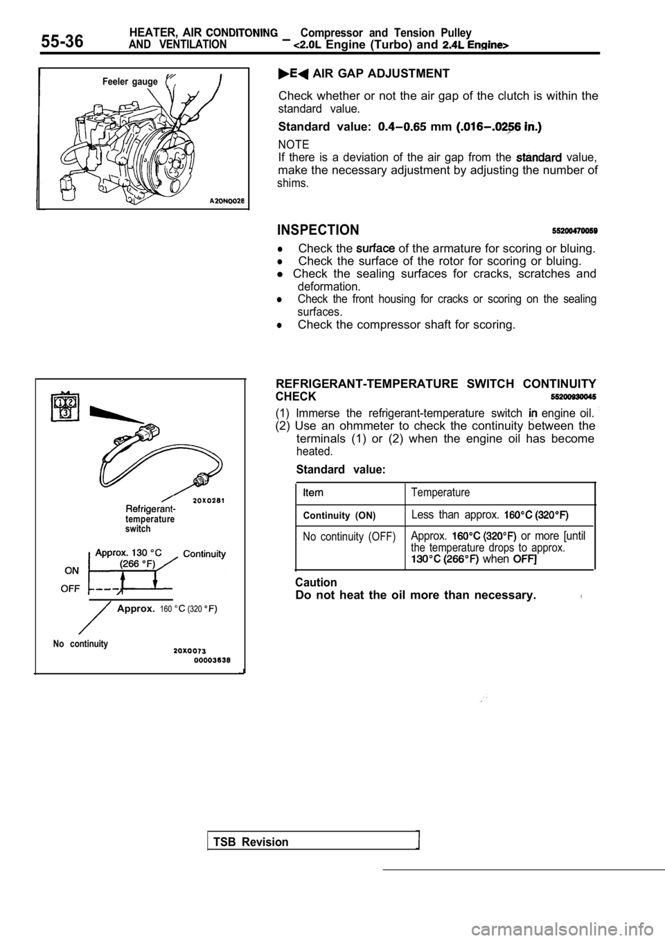
REFRIGERANT-TEMPERATURE SWITCH CONTINUITY
CHECK
(1) Immerse the refrigerant-temperature switch engine oil.
(2) Use an ohmmeter to check the continuity between the
terminals (1) or (2) when the engine oil has become
heated.
TSB Revision
Approx. 160 (320
No continuity
Standard value:
Temperature
Continuity (ON)Less than approx.
No continuity (OFF)Approx. or more [until
the temperature drops to approx.
when
Caution
Do not heat the oil more than necessary.,
Page 2079 of 2103

Compressor
AND VENTILATION,
REMOVAL SERVICE
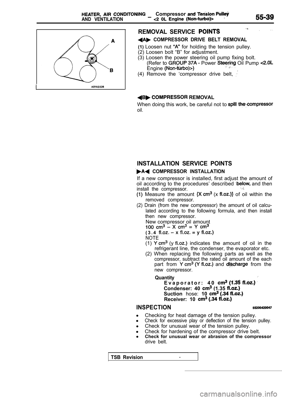
COMPRESSOR DRIVE BELT REMOVAL
(1)Loosen nut for holding the tension pulley.
(2) Loosen bolt “B” for adjustment.
(3) Loosen the power steering oil pump fixing bolt. (Refer to
Power Oil Pump
Engine
(4) Remove the ‘compressor drive belt,
REMOVAL
When doing this work, be careful not to
oil.
INSTALLATION SERVICE POINTS
COMPRESSOR INSTALLATION
If a new compressor is installed, first adjust the amount of
oil according to the procedures’ described
and then
install the compressor.
Measure the amount (x of oil within the
removed compressor.
(2) Drain (from the new compressor) the amount of o il calcu-
lated according to the following formula, and then install
then new compressor.
New compressor oil amount
( 3 . 4
NOTE
(1) (y indicates the amount of oil in the
refrigerant line, the condenser, the evaporator etc .
(2) When replacing the following parts as well as t he
compressor, subtract the rated oil amount of the each
part from and from the
new compressor.
Quantity
E v a p o r a t o r : 4 0
Condenser: 40 (1.35
Suctionhose:10
Receiver: 10
INSPECTION
l
Checking for heat damage of the tension pulley.
l
Check for excessive play or deflection of the tensi on pulley.
l
Check for unusual wear of the tension pulley.
l Check for hardening of the compressor drive belt.
l Check for unusual wear or abrasion of the compresso r
drive belt.
TSB Revision.
Page 2081 of 2103
and Tension
Engine (Non-turbo)>
Bolt mm in.)]
Socket
Deep socket
(14 mm
in.)]
TSB
HUB REMOVAL
(1) Remove the clutch hub mounting bolt.
(2) Tighten a
mm in.) bolt into the hole of the
clutch hub to remove the serration assembly the shaft
and the clutch hub.
SEAL INSTALLATION
Use a 21 mm in.) socket to install the shaft seal so
that the O-ring assembly side is facing the front h ousing.
FELT, FELT HOLDER INSTALLATION
After installing the felt in the felt holder, them to the
front housing using a 14 mm
deep socket.
FRONT HOUSING INSTALLATION
(1) Apply compressor oil to the shaft.
Compressor oil: ND-OIL 8
(2) Install the front housing without damaging the shaft seal
lip.
(3) After installing the front housing, install the clutch hub
mounting bolt to the shaft, and check that the breakaway
torque is within the torque value.
Breakaway torque:
Nm (4 or less
Page 2088 of 2103
HEATER, AIR Condenser and
Condenser Fan’ Motor
TurboNon-turbo
REMOVAL SERVICE POINT ,
REMOVAL,
Move the radiator to the engine side and then lift up the
condenser to remove it.
INSTALLATION SERVICE POINT
CONDENSER INSTALLATION
When replacing the condenser with a new one, refill the con-
denser with a specified amount of compressor oil.
Engine (Turbo) and
Compressor oil: SUN PAG 56
Quantity: 15
Engine (Non-turbo)>
Compressor oil: ND-OIL 8
Quantity: 40
(1.35
INSPECTION
CONDENSER FAN MOTOR CHECK
(1)Check that the condenser fan motor operates when ba ttery
voltage is applied to terminal 1 and terminal 4 is
grounded
(2)In this same condition, apply battery voltage to terminal
3 and grounded terminal 2. Check that the condenser
fan motor operates faster at this time.
TSB Revision