Page 1610 of 2103
FRONT SUSPENSION Shock Absorber
Damper foinstallation
of the body
REASSEMBLY. SERVICE
COIL SPRING INSTALLATION
(1) Use the special tools to
the coil spring and
install it to the shock absorber.
Caution
Do not use an impact wrench to tighten the bolt of
the special tool.
(2) Align the edge of the coil spring to the steppe d part of
the shock
spring seat.
UPPER BRACKET ASSEMBLY
so that the position as’
in the illustration with respect the fork installation
bolt.
. SELF-LOCKING NUT . .
( 1 )
(2). the special tools and
tighten the
to- the ,
Caution
Do not use an impact wrench.
TSB Revision
Page 1612 of 2103

FRONT SUSPENSION
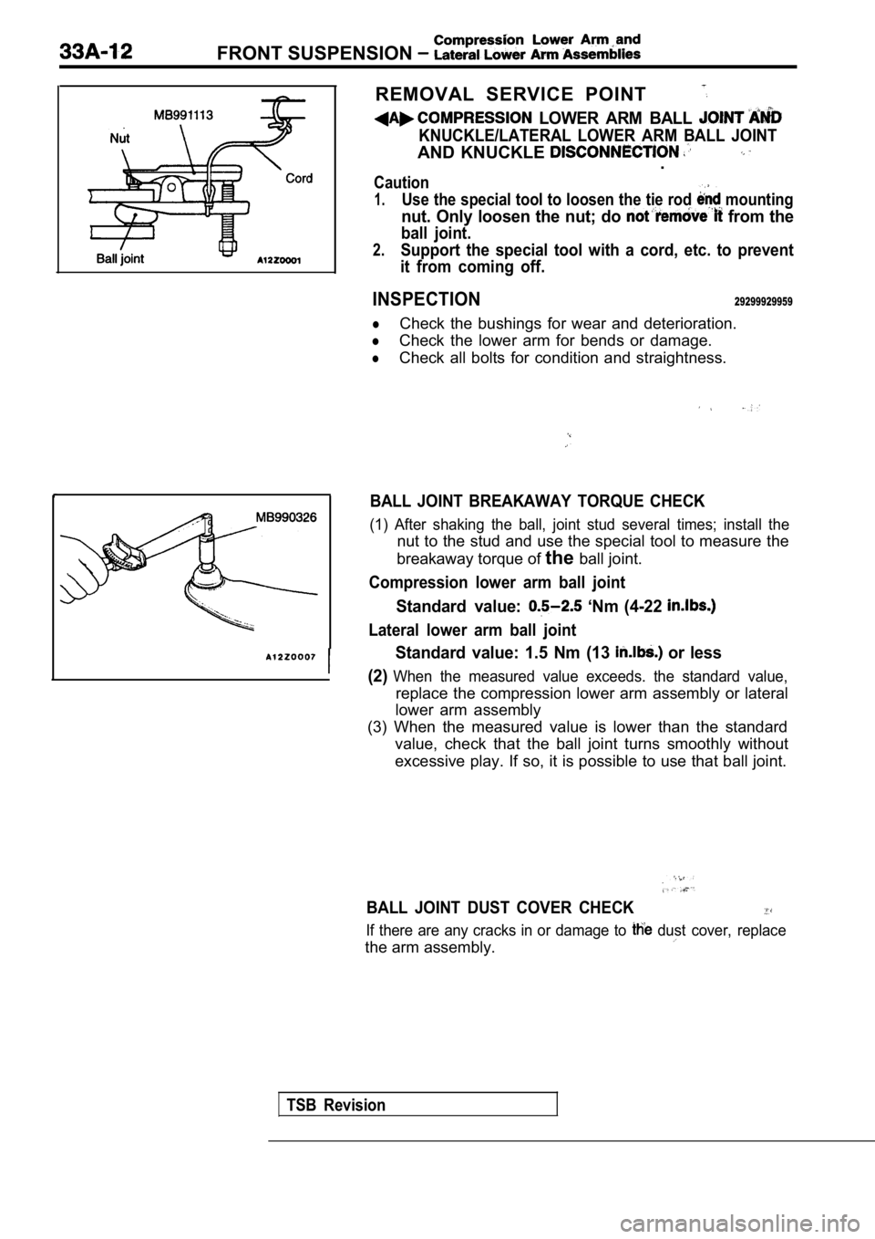
REMOVAL SERVICE POINT
LOWER ARM BALL
KNUCKLE/LATERAL LOWER ARM BALL JOINT
AND KNUCKLE .
Caution
1.Use the special tool to loosen the tie rod mounting
nut. Only loosen the nut; do from the
ball joint.
2.Support the special tool with a cord, etc. to prevent
it from coming off.
INSPECTION29299929959
lCheck the bushings for wear and deterioration.
lCheck the lower arm for bends or damage.
lCheck all bolts for condition and straightness.
BALL JOINT BREAKAWAY TORQUE CHECK
(1) After shaking the ball, joint stud several time s; install the
nut to the stud and use the special tool to measure the
breakaway torque of theball joint.
Compression lower arm ball joint
Standard value: ‘Nm (4-22
Lateral lower arm ball joint
Standard value: 1.5 Nm (13 or less
(2)
When the measured value exceeds. the standard value ,
replace the compression lower arm assembly or lateral
lower arm assembly
(3) When the measured value is lower than the stand ard
value, check that the ball joint turns smoothly wit hout
excessive play. If so, it is possible to use that b all joint.
BALL JOINT DUST COVER CHECK
If there are any cracks in or damage to dust cover, replace
the arm assembly.
TSB Revision
Page 1614 of 2103
STABILIZER BAR
REMOVAL AND INSTALLATION
Removal steps
1. Stabilizer link mounting nut
2. Stabilizer link
3. Stabilizer bar bracket
39 Nm
28
4. Bushing5. Stabilizer bar
INSTALLATION SERVICE POINT
STABILIZER BAR BRACKET INSTALLATION
Position the stabilizer bar so that the marking on the stabilizer
bar and the edge of the bracket becomes the referen ce value,
and then tighten the stabilizer bar bracket mounting bolt.
INSPECTION
lCheck the bushings for wear and deterioration.
lCheck the stabilizer bar for deterioration or damag e.
lCheck all bolts for condition and straightness.
TSB Revision
Page 1617 of 2103
REAR
SUSPENSION-
CONTENTS
GENERAL INFORMATION2SHOCK ABSORBER ASSEMBLY. . . . . . . . . . .. . . . . . . . . . . . . . . . ..
LOWER ARM AND TOE CONTROL ARMSPECIAL TOOLS. . . . . . . . . . . . . . . . . . . . . . . . . .4
ASSEMBLIES. . . . . . . . . . . . . . . . . . . . . . . . . . . . .12
STABILIZER BAR. . . . . . . . . . . . . . . . . . . . .
REAR SUSPENSION ASSEMBLY. . . . . . . . . .7.
TRAILING ARM . . . . . . . . . . . . . . . . .11
ON-VEHICLE SERVICE. . . . . . . . . . . . . . . . . . . .6
Rear Wheel Alignment Check. . . . . . . . . . . . . . . . . . . . . .6
and Adjustment
. . . . . . . . . . . . . . . . . . . . . . . . . . . . .6UPPER ARM ASSEMBLY. . . . . . . . . . . . . . . . . . . .9
SERVICE SPECIFICATIONS . . . . . . . . . . . . . . . .
4
Page 1620 of 2103
REAR SUSPENSION Service Specifications/Special tools, , .
SERVICE SPECIFICATIONS
Items
Toe-in mm (in.)
Standard value
3
Camber (Vehicles with 1 wheels)
FWD (Vehicles with wheels),
Dimension for positioning upper arm bracket
Thrust angle
Toe control arm ball joint breakaway torque
Stabilizer link ball joint breakaway torque
SPECIAL TOOLS
37.2% 2
3)
Steering linkage puller
Preload socket
.
installation
Ball joint remover and
installer
TSB Revision
Page 1622 of 2103
34-6REAR SUSPENSION Service
REAR WHEEL
ADJUSTMENT,Measure. wheel alignment with
ground.
The rear suspension and be serviced to the
normal condition prior to wheel alignment.
. .
T O E - I N
Standard 3 3 mm. in.)
Turn the toe control arm bolt to the left or right
by equal amounts to adjust..
L.H.: Turning clockwise toe-out direction
R.H.: Turning clockwise toe-in
Furthermore, toe adjustment can be made at graduati ons
of
1.3 mm tn.).
CAMBER’
Standard value:
(Vehicles with wheels)
wheels), AWD
NOTE
1.Camber is preset at the’factory and can not be adju sted.
2. If is not within the, standard value, check and
bent or
TSB Revision
Page 1623 of 2103

REAR SUSPENSION Rear Suspension
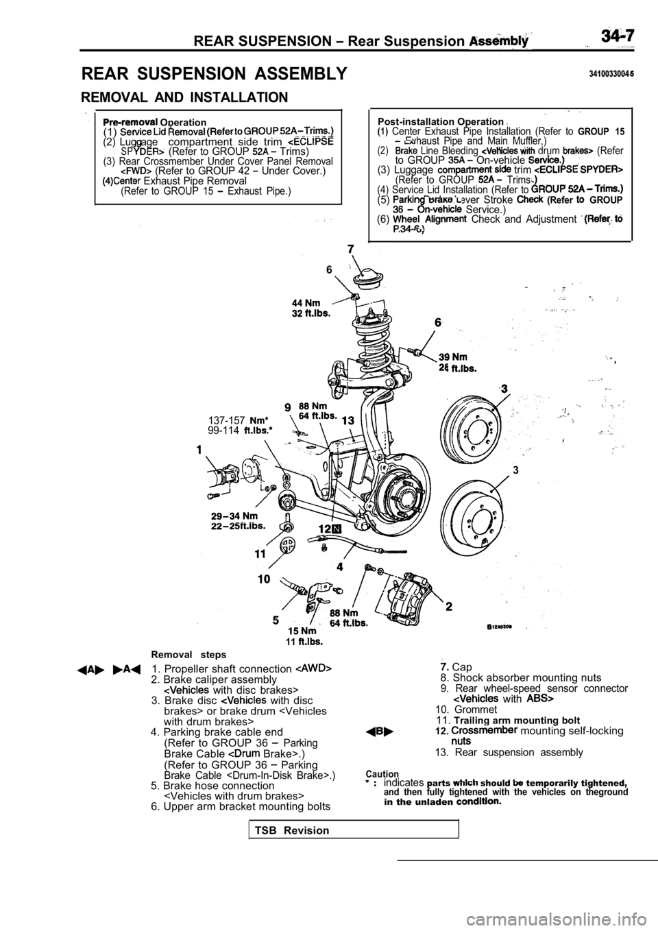
REAR SUSPENSION ASSEMBLY
REMOVAL AND INSTALLATION
Operation
(1)
(2) Lug agecompartment side trim SP (Refer to GROUP Trims)(3) Rear Crossmember Under Cover Panel Removal (Refer to GROUP 42 Under Cover.) Exhaust Pipe Removal(Refer to GROUP 15 Exhaust Pipe.)
3410033004
Post-installation Operation Center Exhaust Pipe Installation (Refer to GROUP 15Exhaust Pipe and Main Muffler,)(2) Line Bleeding drum (Referto GROUP On-vehicle (3) Luggage trim (Refer to GROUP Trims.
(4) Service Lid Installation (Refer to
(5) Brake Lever Stroke (Refer GROUP Service.)
(6) Check and Adjustment .
6
,
137-15799-114
.
l. .
3
Removal steps
11
1. Propeller shaft connection 2. Brake caliper assembly with disc brakes>
3. Brake disc with disc
brakes> or brake drum
with drum brakes>
4. Parking brake cable end
(Refer to GROUP 36
ParkingBrake Cable Brake>.)
(Refer to GROUP 36
ParkingBrake Cable .)5. Brake hose connection
6. Upper arm bracket mounting bolts
Cap
8. Shock absorber mounting nuts
9. Rear wheel-speed sensor connector with 10. Grommet11. Trailing arm mounting bolt
12. mounting self-locking
13. Rear suspension assembly
Cautionindicatesparts should temporarily tightened,and then fully tightened with the vehicles on thegr oundin the unladen
TSB Revision
Page 1624 of 2103
REAR SUSPENSION Rear Suspension Assembly .
REMOVAL SERVICE POINTS
S H A F T
(1) Make mating marks on the differential-
and flange yoke, and then separate the differential carrier
assembly and the propeller shaft.
(2) Suspend the propeller shaft from the body, wire, etc,
so that there are no sharp bends..,
Caution
Be careful that there are no sharp bends in the pro pel-
ler shaft, as they may damage the joint.
CROSSMEMBER MOUNTING SELF-LOCKING
NUTS REMOVAL
After supporting the crossmember in FWD vehicles or the
differential case in AWD vehicles with a garage jack or trans-
mission jack respectively, remove the crossmember m ounting
nuts.
INSTALLATION SERVICE POINT
PROPELLER SHAFT INSTALLATION
Install with the mating marks of the differential carrier and
propeller aligned.
Caution
Tighten installation bolts and nuts after removing oil and
grease from threads to prevent them from loosening.
INSPECTION
lCheck crossmember for cracks or damage.
,
TSB Revision