Page 1536 of 2103
General Information/Service Specifications/
REAR AXLE Special Tools
The rear axle consists of a knuckle, rear hub, unit
bearing and axle shaft. The unit bearing is
fitted to the rear axle shaft and bolted to the knuckle.
Also, the unit bearing utilizes the same type of
double row angular contact ball bearing as does
the front axle.
On, ABS, a ABS rotor
for detecting the speed is located on the
and sensor is located on
the knuckle.
Rear rotor
UnitOil seal
Items
Wheel bearing end play mm (in.)
Wheel bearing rotary-sliding resistance
(Ibs.) Limit
, ,
0.05
1 8 ( 3 . 9 )
ToolTool number and name
113
Steering linkage puller
248
Inner shaft remover
Supersession Application,
Toe’ arm ball and
k n u c k l e r e m o v a l ’
.
I
. .
TSB Revision
Page 1538 of 2103
REAR AXLE On-vehicle Service
HUB BOLT
1. Remove the caliper assembly and with
so that it does not fall.
2. Remove the brake drum and- brake disc.
3.For vehicles with disc brakes;’
assembly..
4. Pull the hub bolt using the special
NOTE
For vehicles with drum
near the retainer in
order to maintain
C a u t i o n
Be sure to tie the cord of a nearby
part.,
5.Use the wheel nuts to securely install the new hub bolts,
while being careful of the serrations of the hub bo lts and
hub.
TSB Revision
.
,
,
,
Page 1540 of 2103
REAR AXLE Rear Hub
REMOVAL SERVICE
CALIPER ASSEMBLY ,
Remove the caliper assembly it.
Socket
ABS ROTOR
TSBRevision
INSTALLATION SERVICE POINT
ROTOR INSTALLATION
INSPECTION
lCheck the oil seal for crack or damage.
lCheck the ABS rotor for chipped teeth.
27100210105
Page 1542 of 2103
REAR AXLE Knuckle
REMOVAL SERVICE POINT
,
TOE CONTROL BALL AND
Caution,1.Use the special to
nut. Only loosen the do the
ball joint.
2. the special tool with a
it from coming off.
TSB Revision
Page 1545 of 2103
REAR AXLE Special Tools
Preload socket
General service toolPrevention of entry of foreign
objects into the differential
General service tool
Working base adapter
,
TSB Revision
Page 1550 of 2103
6REAR AXLE Service
REAR AXLE TOTAL BACKLASH
If the vehicle produces a booming sound due
to an of driving system, measure the rear
total backlash by the following procedures to see if the
carrier assembly requires removal.
1. Place the gearshift lever in theneutral position, apply
the parking brake and
up the vehicle.
Mating marks2.Manually turn the propeller. shaft as far as it
will go and make mating marks flange
dust cover and the differential carrier. ,
3.Manually turn the propeller shaft counterclockwise as far
as it will go and measure the of the mating!
marks.
Limit: 5 mm in.)
4.If the backlash exceeds’ the limit, remove the differential
carrier assembly (Refer to and adjust the back-
lash (Refer to
TSB Revision
GEAR OIL LEVEL
Remove the filler plug, check, the level. .
2.The oil is sufficient if hole.
Specified gear oil: ,
API classification
NOTEO v e r S A E
Under SAE
Page 1551 of 2103

REAR AXLE On-vehicle Service
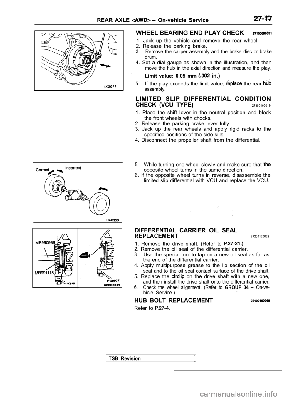
WHEEL BEARING END PLAY CHECK
1. Jack up the vehicle and remove the rear wheel.
2. Release the parking brake.
3.Remove the caliper assembly and the brake disc or b rake
drum.
4. Set a dial gauge as shown in the illustration, and then
move the hub in the axial direction and measure the play.
Limit value: 0.05 mm in.)
5.If the play exceeds the limit value, the rear
assembly.
LIMITED SLIP DIFFERENTIAL CONDITION
CHECK (VCU TYPE)27300100019
1. Place the shift lever in the neutral position an d block
the front wheels with chocks.
2. Release the parking brake lever fully.
3. Jack up the rear wheels and apply rigid racks to the
specified positions of the side sills.
4. Disconnect the propeller shaft from the differen tial.
5.While turning one wheel slowly and make sure that
opposite wheel turns in the same direction.
6. If the opposite wheel turns in reverse, disassem ble the
limited slip differential with VCU and replace the VCU.
DIFFERENTIAL CARRIER OIL SEAL
REPLACEMENT27200120022
1. Remove the drive shaft. (Refer to
2. Remove the oil seal of the differential carrier.
3.Use the special tool to tap on a new oil seal as fa r as
the end of the differential carrier.
4. Apply multipurpose grease to the lip section of the oil
seal and to the oil seal contact surface of the drive shaft.
5. Replace the on the drive shaft with a new one,
and then install the drive shaft onto the differential carrier.
6.Check the wheel alignment. (Refer to GROUP 34 On-ve-
hicle Service.)
HUB BOLT REPLACEMENT
Refer to
TSB Revision1
Page 1555 of 2103
REAR AXLE Drive
2 7 1 0 0 3 3 0 0 2 3
REMOVAL AND INSTALLATION
Brake Line Bleeding with drum brakes>
(Refer to GROUP 36
On-vehicle Service.)
9871
I I10
,19
44118-1373385-99
11
with drum brakes>
11
9871. .,
Removal steps
1. Rear wheel speed sensor
2. Caliper assembly (Refer to 3. Brake disc
4. Brake drum
5. Shoe and lining assembly (Refer to
GROUP 36
Parking Brake.)6. Shoe and lever assembly
7. Clip8. Parking brake cable
9. Brake pipe connection
10. Shock absorber connection Trailing arm connection12. Lower arm connection
13. Toe control armball joint andknuckle connection(Refer to 14. pin 15. Drive shaft nut16. Washer
17. Differential mount support
18. Drive shaft
19.
Caution1.For vehicles with ABS, careful not to damagedrive shaft rotor.2.l : Indicates parts should be temporarily and then fully tightened the on the
ground in the unladen condition.
TSB Revision