Page 1556 of 2103
REAR AXLE Shaft
REMOVAL SERVICE POINTS
,
DRIVE SHAFT REMOVAL
(1) Push the lower part of the knuckle
the of the
vehicle, and then separate the differen-
tial carrier. At fhis time, use a tire or similar to
separate the drive shaft connection.
.
(2) Use the special tool as a not to let
get into the differential carrier. ,
,
TSB Revision
Page 1557 of 2103
REAR AXLE Shaft
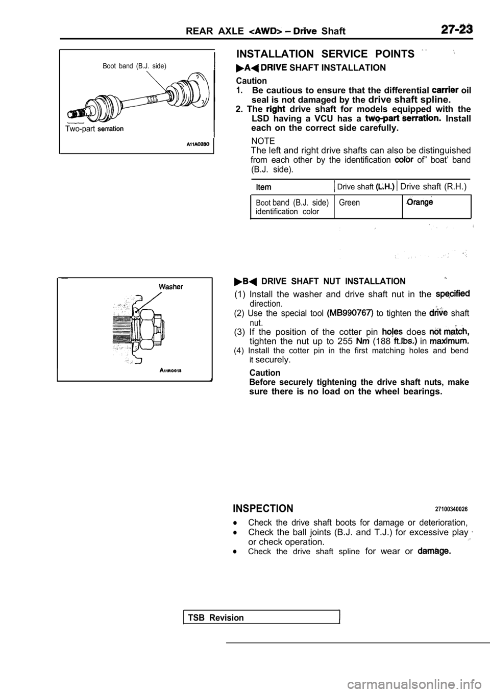
Boot band (B.J. side)
Two-part
INSTALLATION SERVICE POINTS
SHAFT INSTALLATION
Caution
1.Be cautious to ensure that the differential oil
seal is not damaged by the drive shaft spline.
2. The
drive shaft for models equipped with the
LSD having a VCU has a
Install
each on the correct side carefully.
NOTE
The left and right drive shafts can also be disting uished
from each other by the identification of” boat’ band
(B.J. side).
Drive shaft Drive shaft (R.H.)
Bootband (B.J. side) Green
identification color
DRIVE SHAFT NUT INSTALLATION
(1) Install the washer and drive shaft nut in the
direction.
(2) Use the special tool to tighten the shaft
nut.
(3) If the position of the cotter pin does
tighten the nut up to 255 (188 in
(4) Install the cotter pin in the first matching ho les and bend
it securely.
Caution
Before securely tightening the drive shaft nuts, ma ke
sure there is no load on the wheel bearings.
INSPECTION27100340026
lCheck the drive shaft boots for damage or deterioration,
lCheck the ball joints (B.J. and T.J.) for excessive play
or check operation.
lCheck the drive shaft spline for wear or
TSB Revision
Page 1559 of 2103
REAR AXLE Drive Shaft
LUBRICATION POINTS
Grease:
Repair kit grease 75 (2.66 oz.)
Caution
The drive shaft uses special
grease. Do not mix old and new or
different types of grease. Grease: Repair kit grease
95
(3.35 oz.)
105
(3.70 oz.)
Caution
drive shaftjointuses special grease.
not mix old and new or different types of grease.
DISASSEMBLY SERVICE POINTS
SNAP RING/SPIDER ASSEMBLY REMOVAL
(1) Wipe out the grease in the T.J. case. ,
TSB Revision
Page 1560 of 2103
R E A R A X L E
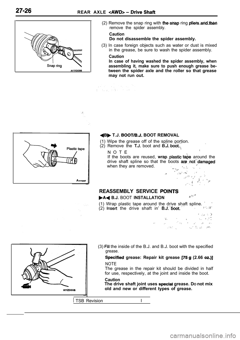
(2) Remove the snap ring with ring
remove the spider assembly.
Caution
Do not disassemble the spider assembly.
(3) In case foreign objects such as water or dust i s mixed
in the grease, be sure to wash the spider assembly.
Caution
In case of having washed the spider assembly, when
assembling it, make sure to push enough grease be-
tween the spider axle and the roller so that grease may not run out.
T.J. BOOT REMOVAL
(1) Wipe the grease off of the spline portion.
(2) Remove the
boot and
N O T E
If the boots are reused, around the
drive shaft spline so that the boots
when they are removed. __
REASSEMBLY SERVICE
B.J. BOOTINSTALLATION
(1) Wrap plastic tape around the drive shaft spline .
(2) the drive shaft in’
. . .,
(3) the inside of the B.J. and B.J. boot with the specified
grease.
grease: Repair kit grease (2.66
NOTE
The grease in the repair kit should be divided in h alf
for use, respectively, at the joint and inside the boot.
Caution
The drive shaft joint uses grease. DOnot mix
old and new or different types of grease.
TSB Revision I
Page 1563 of 2103
REAR AXLE Differential Carrier
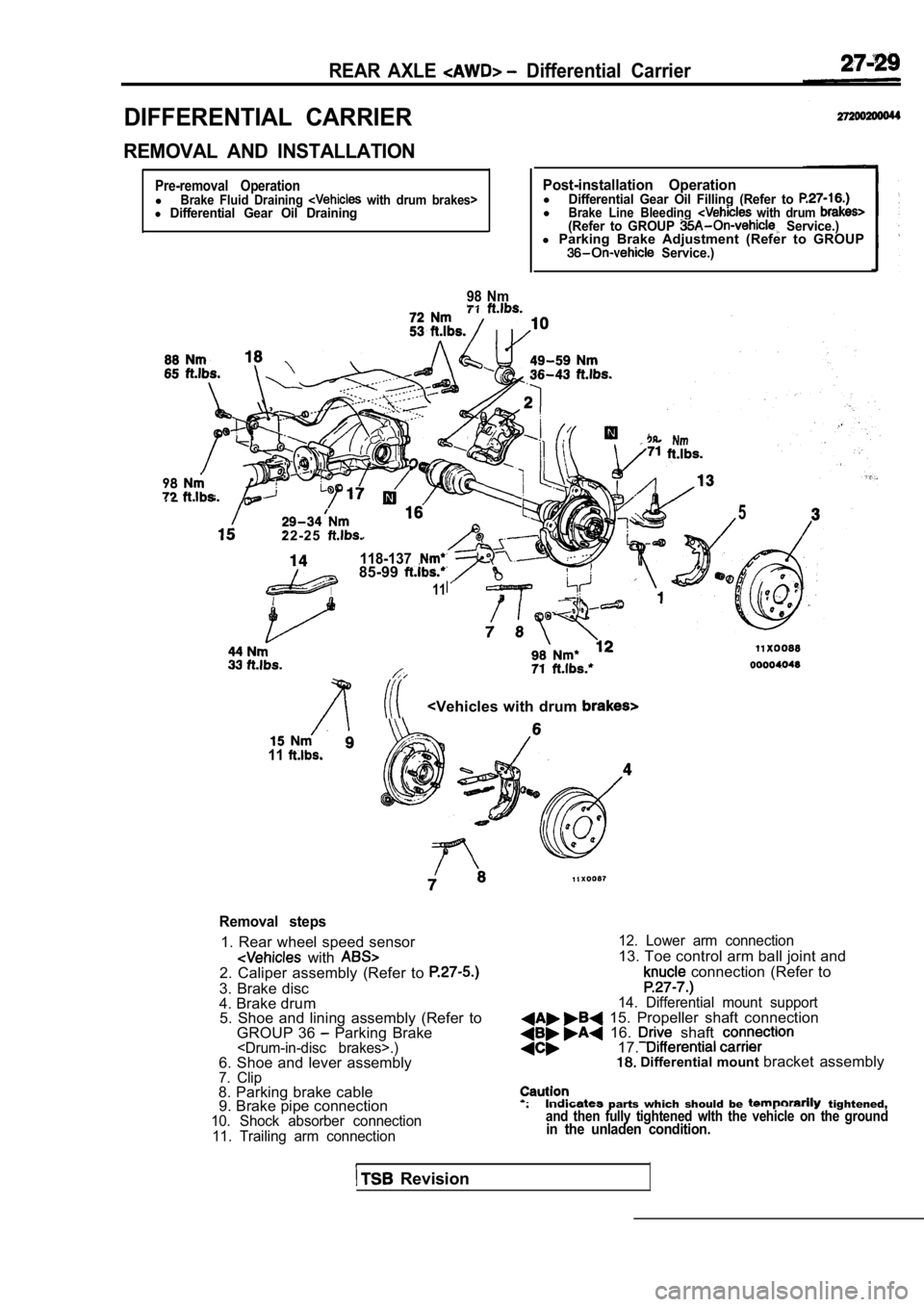
DIFFERENTIAL CARRIER
REMOVAL AND INSTALLATION
Pre-removal OperationlBrake Fluid Draining with drum brakes>l Differential Gear Oil Draining
98 Nm
Post-installation OperationlDifferential Gear Oil Filling (Refer to lBrake Line Bleeding with drum (Refer to GROUP Service.)l Parking Brake Adjustment (Refer to GROUP Service.)
98
2 2 - 2 5
118-13785-99
11
5
11
Removal steps
1. Rear wheel speed sensor
with 2. Caliper assembly (Refer to
3. Brake disc
4. Brake drum
5. Shoe and lining assembly (Refer to
GROUP 36
Parking Brake.)6. Shoe and lever assembly7. Clip8. Parking brake cable9. Brake pipe connection
10. Shock absorber connection
11. Trailing arm connection 12. Lower arm connection
13. Toe control arm ball joint and
connection (Refer to
14. Differential mount support 15. Propeller shaft connection 16. shaft 17. Differential mount
bracket assembly
parts which should be tightened,and then fully tightened wlth the vehicle on the gr oundin the unladen condition.
Revision
Page 1564 of 2103
R E A R A X L E D i f f e r e n t i a l
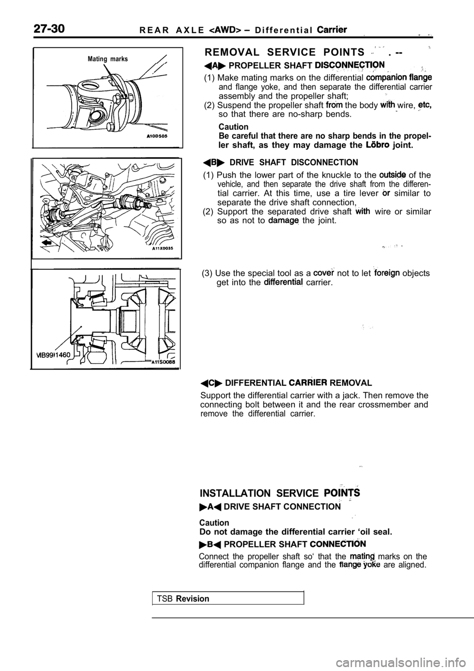
Mating marksR E M O V A L S E R V I C E P O I N T S . --
PROPELLER SHAFT
(1) Make mating marks on the differential
and flange yoke, and then separate the differential carrier
assembly and the propeller shaft;
(2) Suspend the propeller shaft the body wire,
so that there are no-sharp bends.
Caution
Be careful that there are no sharp bends in the pro pel-
ler shaft, as they may damage the joint.
DRIVE SHAFT DISCONNECTION
(1) Push the lower part of the knuckle to the of the
vehicle, and then separate the drive shaft from the differen-
tial carrier. At this time, use a tire lever similar to
separate the drive shaft connection,
(2) Support the separated drive shaft
wire or similar
so as not to
the joint.
(3) Use the special tool as a
not to let objects
get into the
carrier.
DIFFERENTIAL REMOVAL
Support the differential carrier with a jack. Then remove the
connecting bolt between it and the rear crossmember and
remove the differential carrier.
INSTALLATION SERVICE
DRIVE SHAFT CONNECTION
Caution
Do not damage the differential carrier ‘oil seal.
PROPELLER SHAFT
Connect the propeller shaft so‘ that the marks on the
differential companion flange and the
are aligned.
TSB
Revision
Page 1569 of 2103
REAR AXLE Differential ‘Carrier
DISASSEMBLY SERVICE POINTS
DIFFERENTIAL CASE ASSEMBLY
Caution
the differential case slowly
fully so that the side bearing race is not
NOTE
Keep the right and left side bearings separate, so that they
do not become mixed at the time of reassembly.
BEARING INNER RACE REMOVAL
Place the nut on top of the differential case, and then use
the special tool to remove the side bearing inner r ace.
NOTE
Attach the prongs of the special tool to the inner ‘race of
the side bearing through the openings in the differential case.
DRIVE GEAR REMOVAL
(1) Make the mating marks to the differential case and the
drive gear.
(2) Loosen the drive gear attaching bolts in diagon al se-
quence to remove the drive gear.
LOCK PIN REMOVAL differential>
NUT REMOVAL
Revision
Page 1573 of 2103
REARAXLE Differential
Front bearingRear bearing1
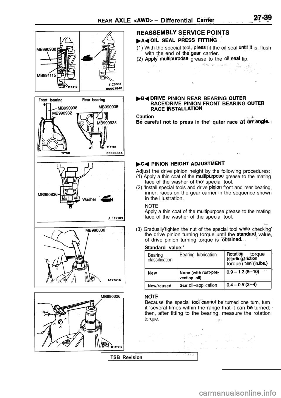
SERVICE POINTS
(1) With the special fit the oil seal is. flush
with the end of
carrier.
(2)
grease to the lip.
PINION REAR BEARING
RACE/DRIVE PINION FRONT BEARING
RACE
Caution
careful not to press in the’ quter race at
PINION
Adjust the drive pinion height by the following pro cedures:
(1) Apply a thin coat of the grease to the mating
face of the washer of special tool.
(2) ‘Install special tools and drive front and rear bearing,
inner. races on the gear carrier in the sequence sh own
in the illustration.
NOTE
Apply a thin coat of the multipurpose grease to the mating
face of the washer of the special tool.
(3) Gradually’tighten the nut of the special tool checking’
the drive pinion turning torque until the value,
of drive pinion turning torque is
Standard value:’
Bearing Bearing lubrication
classification torque
torque)
N e wNone (with
ventiop oil)
New/reused
Gearoil--application
TSB Revision
Because the special be turned one turn, turn
it ‘several times within the range that it can turned;
then, after fitting to the bearing, measure the rot ation
torque.