Page 1672 of 2103
BASIC BRAKE SYSTEM Front
Lock pin
DISASSEMBLY SERVICE
When disassembling the disc brakes, disassemble both sides
(left and right) as a set.
PISTON BOOT/PISTON
Protect caliper body with cloth. Blow compressed air through
brake hose to remove piston boot and
Caution
Blow air gently.
SEAL REMOVAL
(1) Remove piston seal with finger tip.
Caution
Do not use a flat-tipped screwdriver or other tool to
prevent damage to inner cylinder.
( 2 ) C l e a n p i s t o n s u r f a c e a n d , i n n e r c y l i n d e r w i t h trichloro-ethylene, alcohol, or specified brake flu id.
Specified brake fluid:
REASSEMBLY SERVICE POINTS
PIN
INSTALLATION
(1) Grease parts as illustrated with specified grea se.
Specified grease: Repair kit grease (orange)
(2) Install the guide pin and lock pin as illustrat ed
eath
head mark of the auide
and the pin matches
the indication
or located the caliper
body.
TSB Revision
Page 1679 of 2103
BASIC BRAKE SYSTEM Rear Brake
REMOVALPin shoe assembly RETAINER REMOVAL
Use an flat-tipped screwdriver or the like to up the
retainer joint, and remove the retainer.
Retainer
INSTALLATION SERVICE POINTS
WAVE WASHER INSTALLATION
Install the washer in the direction shown in the il lustration.
Parking lever
Pin of shoe assembly
Retainer
RETAINER
Use pliers or the like to install the retainer on t he pin securely.
TSB Revision1
Page 1683 of 2103
BASIC BRAKE SYSTEM Rear Disc Brake
REAR DISC BRAKE
REMOVAL AND INSTALLATION
I
I OperationlLoosening Parking Brake Cable Adjusting Nut..
l Brake Fluid DrainingPost-installation ‘OperationlBrake Fluid Filling andAir(Refer to lParking Brake Lever Adjustment
(Refer to GROUP 36 On-vehicle Service.)
49-59
36-43
3
Removal steps
1. Brake hose connection 2. Rear brake assembly
3. Brake disc .
INSTALLATION SERVICE POINT
REAR BRAKE ASSEMBLY INSTALLATION
Install
the rear brake assembty and disc
drag torque. (Refer to
INSPECTION
lCheck the brake disc for damage.
l Check the brake disc for thickness.
l Check the brake disc for run-out.
TSB Revision
Page 1685 of 2103
BASICB R AKE SYSTEM Rear Disc
LUBRICATION POINTS
IGrease: Repair kit greaseI
CautionThe piston seal inside the seal andboot kit is coated with special grease.Do not wipe this grease off.
Brake fluid:
or
TSB Revision
Grease: Repair kit grease
DISASSEMBLY SERVICE POINTS
When disassembling the disc brakes, disassemble bot h sides
(left and right) as a set.
PISTON BOOT/PISTON REMOVAL
Protect caliper body with cloth. Blow compressed air through
brake hose to remove piston boot and piston.
Caution
Blow compressed air gently.
PISTON SEAL REMOVAL
(1) Remove piston seal with finger tip.
Caution
Do not use a flat-tipped screwdriver or other tool to
prevent damage to inner cylinder.
( 2 ) C l e a n p i s t o n s u r f a c e a n d i n n e r c y l i n d e r w i t h trichloro-ethylene, alcohol or specified brake flui d.
Specified brake fluid:
or
Page 1686 of 2103

BASICBRAKESYSTEM Rear Disc Brake
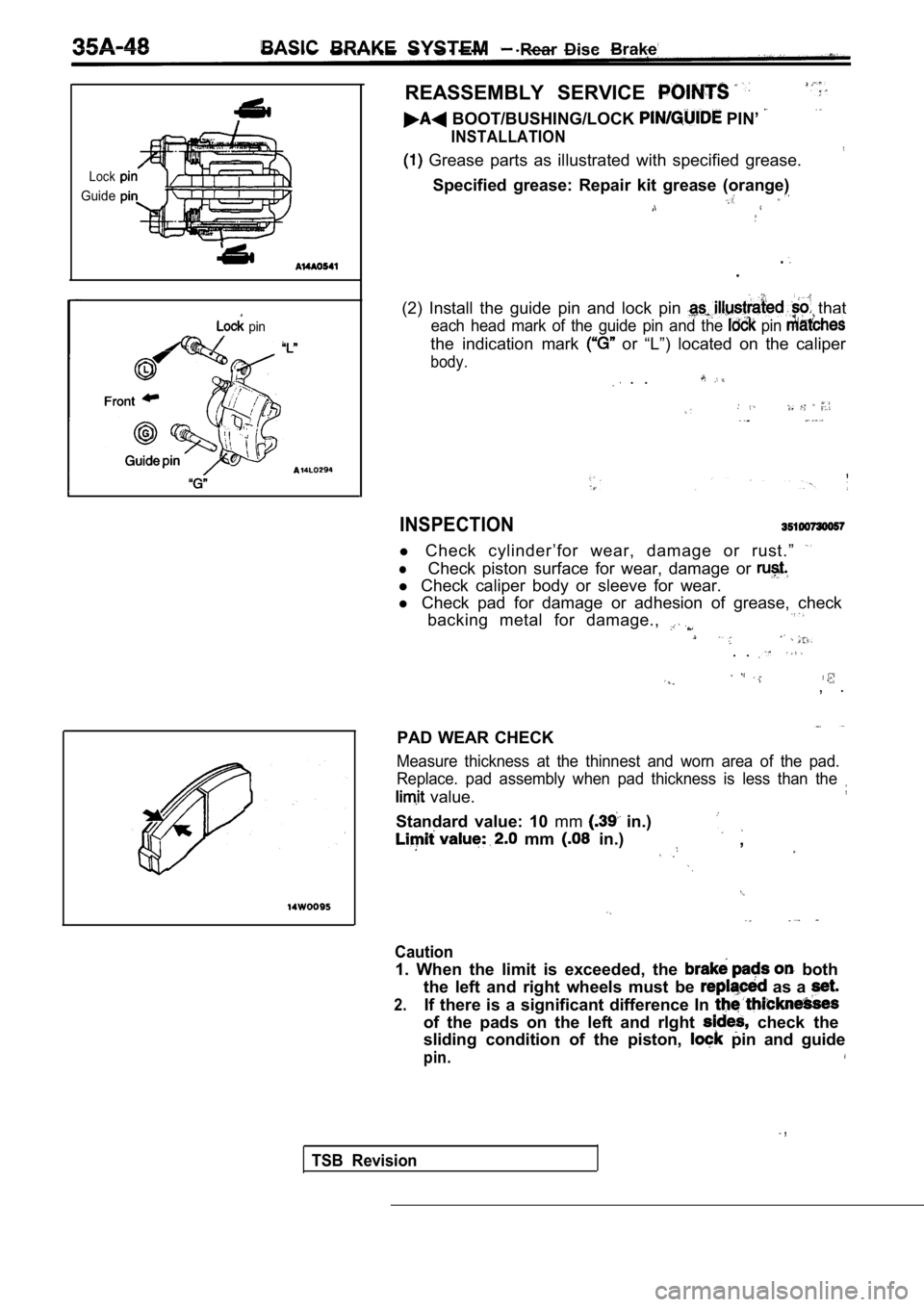
Lock
Guide
pin
REASSEMBLY SERVICE
BOOT/BUSHING/LOCK PIN’
INSTALLATION
Grease parts as illustrated with specified grease.
Specified grease: Repair kit grease (orange)
..
(2) Install the guide pin and lock pin
that
each head mark of the guide pin and the pin
the indication mark or “L”) located on the caliper
body.
. .
INSPECTION
l Check cylinder’for wear, damage or rust.”
lCheck piston surface for wear, damage or
l Check caliper body or sleeve for wear.
l Check pad for damage or adhesion of grease, check
backing metal for damage.,
. .
, .
PAD WEAR CHECK
Measure thickness at the thinnest and worn area of the pad.
Replace. pad assembly when pad thickness is less th an the
value.
Standard value: 10 mm in.)
mm in.),
Caution
1. When the limit is exceeded, the both
the left and right wheels must be
as a
2.If there is a significant difference In
of the pads on the left and rlght check the
sliding condition of the piston,
pin and guide
pin.
,
TSB Revision
Page 1689 of 2103

CONTENTS
ABS-ECU. . . . . . . . . . . . . . . . . . . . . . . . . . . . . . . . .41 VALVE. . . . . . . . . . . . . . . . .
GENERAL INFORMATION. . . . . . . . . . . . . . . . .2SERVICE SPECIFICATIONS.. . . . . . . . . . . . . .3
HYDRAULIC UNIT . . . . . . . . . . . . . . . . . . . . . . . . .36SPECIAL TOOLS . . . . . . . . . . . . . . . . . . . . . . . . . .3
MASTER CYLINDER ANDTROUBLESHOOTING.. . . . . . . . . .. . . . . . . . .4
BRAKE BOOSTER. . . . . . . . . . . . . . . . . . . . . . . . .32..
W H E E L S P E E D .. . . .... . . . . . . . . . . . .38
ON-VEHICLE SERVICE24.... . . . . . . . . . . . . . . . . . . .
ABS Operation Check . . . . . . . . . . . . . . . . . . . . . . .
24
Bleeding
. . . . .. . . . . . . . . . . . . . . . . . . . . . . . . . . .24
Refer to GROUP for the following items.
BRAKE PEDAL
FRONT DISC BRAKE
LUBRICANTS
REAR DISC BRAKE
REAR DRUM BRAKE SHOE
REAR DRUM BRAKE WHEEL CYLINDER
ON-VEHICLE SERVICE
Brake Booster Operating Test
Brake Drum inside Diameter Check
Brake Fluid Level Sensor Check
Brake Lining and Brake Drum Contact Check
Brake Lining Thickness Check
Brake Pedal Check and Adjustment
Check Valve Operation Check
Front Brake Disc Run-out Check
Front Brake Disc Run-out Correction
Front Brake Disc Thickness Check
Front Disc Brake Pad Check and Replacement
Front Disc Brake Rotor Check
Proportioning Valve Function Test
Rear Brake Disc Run-out
Rear Brake Disc Run-out
Rear Brake Disc Thickness
Rear Disc Brake Pad and Replacement
S t o p L i g h t S w i t c h
Page 1690 of 2103
ABS General Information
The ABS consists of wheel speed sensors, stop light switch, hydraulic unit and the ABS-ECU. If
a problem occurs in the system, the malfunctioning
system can be identified by means of the diagnostic
function.
The diagnostic trouble code will not be erased even
if the ignition switch is turned to OFF.
In addition, reading of diagnostic trouble codes,
service testing are possible using
t h e s c a n
Items
Wheel speed sensor
Front ABS rotor teeth
Rear ABS rotor teeth
,
Magnet coil type
4 3
43
DIAGRAM
1. ABS-ECU6. ABS rotor7. Data link connector .
6. Stop
9. ABS warning light
2. Hydraulic unit
3. ABS valve relay
4. ABS motor relay
5. Wheel speed sensor
TSB Revision
Page 1691 of 2103
ABSService Specifications/Special ,
SERVICE SPECIFICATIONS2
ItemsStandard value
Hydraulic unit solenoid valve internal resistance
Wheel speed sensor internal resistance I
Clearance between the wheel speed sensor
mounting surface and the ABS rotor mm (in.)2 8 . 2 - 2 8 . 5 ( 1 . 1 1 - 1 . 1 2 )
Wheel speed sensor insulation resistance ioo or more
SPECIAL TOOLS
,
scan tool (MUT-II) is
ABS check harness
TSB Revision