Page 1641 of 2103
BASIC BRAKE. SYSTEM Service Specifications
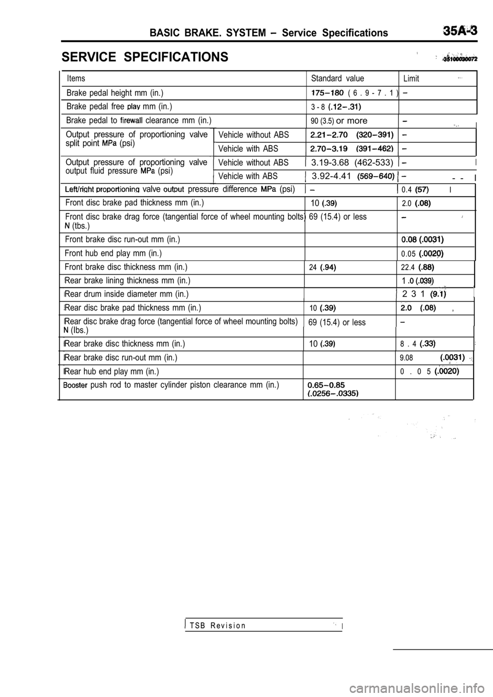
SERVICE SPECIFICATIONS
ItemsStandard valueLimit
Brake pedal height mm (in.) ( 6 . 9 - 7 . 1 )
Brake pedal free mm (in.)3 - 8
Brake pedal to clearance mm (in.)90 (3.5) or moreI
Output pressure of proportioning valve
split point
(psi)
Output pressure of proportioning valve
output fluid pressure (psi) Vehicle without ABS
Vehicle with ABSII
Vehicle without ABS 3.19-3.68 (462-533) I
Vehicle with ABS 3.92-4.41 - - I
valve pressure difference (psi) 0.4 I
Front disc brake pad thickness mm (in.)10
Front disc brake drag force (tangential force of wh
eel mounting bolts) 69 (15.4) or less
(tbs.)
Front brake disc run-out mm (in.)
Front hub end play mm (in.)
2.0
0.05
Front brake disc thickness mm (in.)
Rear brake lining thickness mm (in.)
Rear drum inside diameter mm (in.)2422.4
1
2 3 1 1
Rear disc brake pad thickness mm (in.)10 ,
Rear disc brake drag force (tangential force of whe el mounting bolts)
69 (15.4) or less
(Ibs.)
Rear brake disc thickness mm (in.)
108 . 4
Rear brake disc run-out mm (in.)
Rear hub end play mm (in.)
push rod to master cylinder piston clearance mm (i n.)
9.08
0 . 0 5
T S B R e v i s i o nI
Page 1642 of 2103
BASIC BRAKE SYSTEM Tools
LUBRICANTS
,,
Brake fluid
Brake piston seal Specified lubricant or
Repair kit grease
Slide pin boot and slide pin bush inner surfaces
,
Brake piston boot inner surfaces.
Lock pin boot inner surfaces
Guide pin boot inner surfaces
Piston boot mounting grooves
Piston cup surface
Rear brake shoe and backing plate contact surfacesB r a k e g r e a s e 1
Shoe and lining assembly and auto adjuster assembly con-
tact surfaces
“.Shoe and lever assembly and auto adjuster assembly con-
tact surfaces
. .. . .
SEALANT
Items
Thread part fitting
Vacuum switch Specified sealant ATD Part No. 8861 or equivalent sealant ,
.
SPECIAL TOOLS
ToolTool number and nameApplication
T S B R e v i s i o n
Brake tool set General service tool
Compressing front disc
piston
Installation of drum brake
wheel cylinder piston cup
Removal and installation of
front hub
Front hub remover and
installer
Page 1646 of 2103
BASIC BRAKE SYSTEM .,
d o w n ,
Lock nut
TSB Revision
O N - V E H I C L E
BRAKE PEDAL
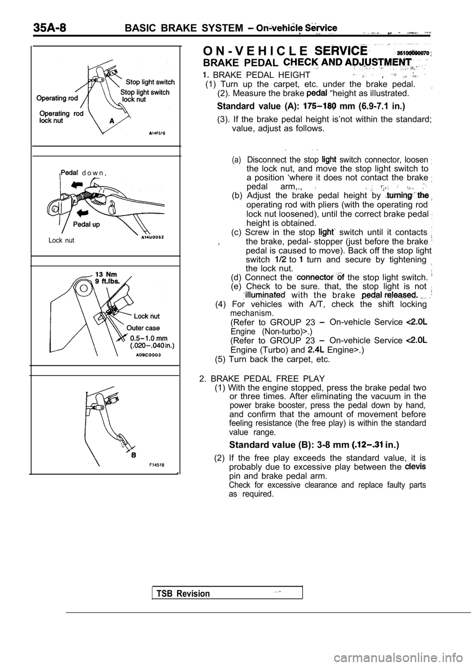
BRAKE PEDAL HEIGHT ,
(1) Turn up the carpet, etc. under the brake pedal.(2). Measure the brake
“height as illustrated.
Standard value (A): mm (6.9-7.1 in.)
(3). If the brake pedal height is’not within the st andard;
value, adjust as follows.
(a)Disconnect the stop switch connector, loosen
the lock nut, and move the stop light switch to
a position ‘where it does not contact the brake
pedal arm,.,
(b) Adjust the brake pedal height by
operating rod with pliers (with the operating rod
lock nut loosened), until the correct brake pedal
height is obtained.
(c) Screw in the stop
switch until it contacts
the brake, pedal- stopper (just before the brake
pedal is caused to move). Back off the stop light
switch
to turn and secure by tightening
the lock nut.
(d) Connect the
the stop light switch.
(e) Check to be sure. that, the stop light is not
with the brake
(4) For vehicles with A/T, check the shift locking
mechanism.
(Refer to GROUP 23 On-vehicle Service
Engine (Non-turbo)>.)
(Refer to GROUP 23 On-vehicle Service
Engine (Turbo) and Engine>.)
(5) Turn back the carpet, etc.
2. BRAKE PEDAL FREE PLAY (1) With the engine stopped, press the brake pedal two
or three times. After eliminating the vacuum in the
power brake booster, press the pedal down by hand,
and confirm that the amount of movement before
feeling resistance (the free play) is within the st andard
value range.
Standard value (B): 3-8 mm in.)
(2) If the free play exceeds the standard value, it is
probably due to excessive play between the
pin and brake pedal arm.
Check for excessive clearance and replace faulty pa rts
as required.
Page 1648 of 2103
BASIC BRAKE SYSTEM On-vehicle Service
GoodNo good
000001
When engine isWhen engine isstopped started
No goodGood
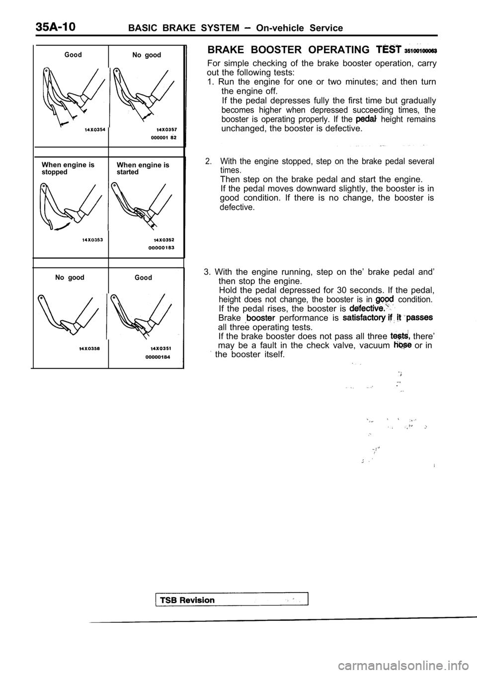
00000184BRAKE BOOSTER OPERATING
For simple checking of the brake booster operation,
carry
out the following tests: 1. Run the engine for one or two minutes; and then turn
the engine off. If the pedal depresses fully the first time but gra dually
becomes higher when depressed succeeding times, the
booster is operating properly. If the
height remains
unchanged, the booster is defective.
2.With the engine stopped, step on the brake pedal se veral
times.
Then step on the brake pedal and start the engine.
If the pedal moves downward slightly, the booster i s in
good condition. If there is no change, the booster is
defective.
3. With the engine running, step on the’ brake peda l and’
then stop the engine. Hold the pedal depressed for 30 seconds. If the ped al,
height does not change, the booster is in condition.
If the pedal rises, the booster is
Brake performance is
all three operating tests.
If the brake booster does not pass all three
there’
may be a fault in the check valve, vacuum
or in
the booster itself.
.
Page 1649 of 2103
BASIC BRAKE SYSTEM Service
Booster
side
CHECK VALVE OPERATION CHECK
When checking the check valve, keep the check valve fit
in the vacuum hose.,
1. Remove the vacuum hose.
NOTE
The check valve is press-fitted inside the vacuum h ose.
2.Check the operation of the check valve by using a v acuum
Vacuum pump connection Accept/reject criteria
Connection at the brake A negative pressure
booster side (A)is created and held.
Connection at the intake A (vacuum)
manifold side (B) is not created.
Caution
If the check valve is defective, replace it as an
assembly unit together with the vacuum hose.
TSB Revision
Page 1652 of 2103
4 SYSTEM Service
Pad
indicator
Brake disc
BRAKE PAD CHECK AND . .
REPLACEMENT
brake ‘pads have wear that contact
disc when ‘the brake pad 2
The wear indicators a to warn
to have the pads replaced h&e
checked.
1.Check. brake pad.
port.
Standard’ 10 mm
,
Limit: 2.0 mm in.)
Caution
When the limit is pads on
both the left and be replaced
as a set.
2. If there is, a significant in the
thicknesses of the pads on the left and right sides,
the sliding condition- of -the
pin guide pin.
2. g u i d e c a l i p e r t h e ”
assembly toward, the inside of the wheel well
from the lock Support it
Caution
Donot wipe off the special guide
pin or allow it to
Page 1654 of 2103
BASIC BRAKE SYSTEM On-vehicle Service
Pad assembly
Grease
Grease Al
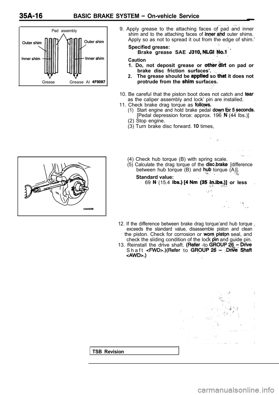
9. Apply grease to the attaching faces of pad and i nner
shim and to the attaching faces of outer shims.
Apply so as not to spread it out from the edge of shim.’
Specified grease:
Brake grease SAE
Caution
1. Do, not deposit grease or on pad or
brake disc friction surfaces’.
2.The grease should be so it does not
protrude from the
surfaces.
10. Be careful that the piston boot does not catch and
as the caliper assembly and lock’ pin are installed.
11. Check brake drag torque as
(1)Start engine and hold brake pedal
[Pedal depression force: approx. 196 (44 Ibs.)]
(2) Stop engine.
(3) Turn brake disc forward.
times,
(4) Check hub torque (B) with spring scale.
(5) Calculate the drag torque of the [difference
between hub torque (B) and torque (A)]. .
Standard value:
69 (15.4 or less,
12. If the difference between brake drag torque’and hub torque
exceeds the standard value, disassemble piston and clean
the piston. Check for corrosion or seal, and
check the sliding condition of the lock
and guide pin.
13. Reinstall the drive shaft.
-to
S h a f t t o
TSB Revision
Page 1655 of 2103
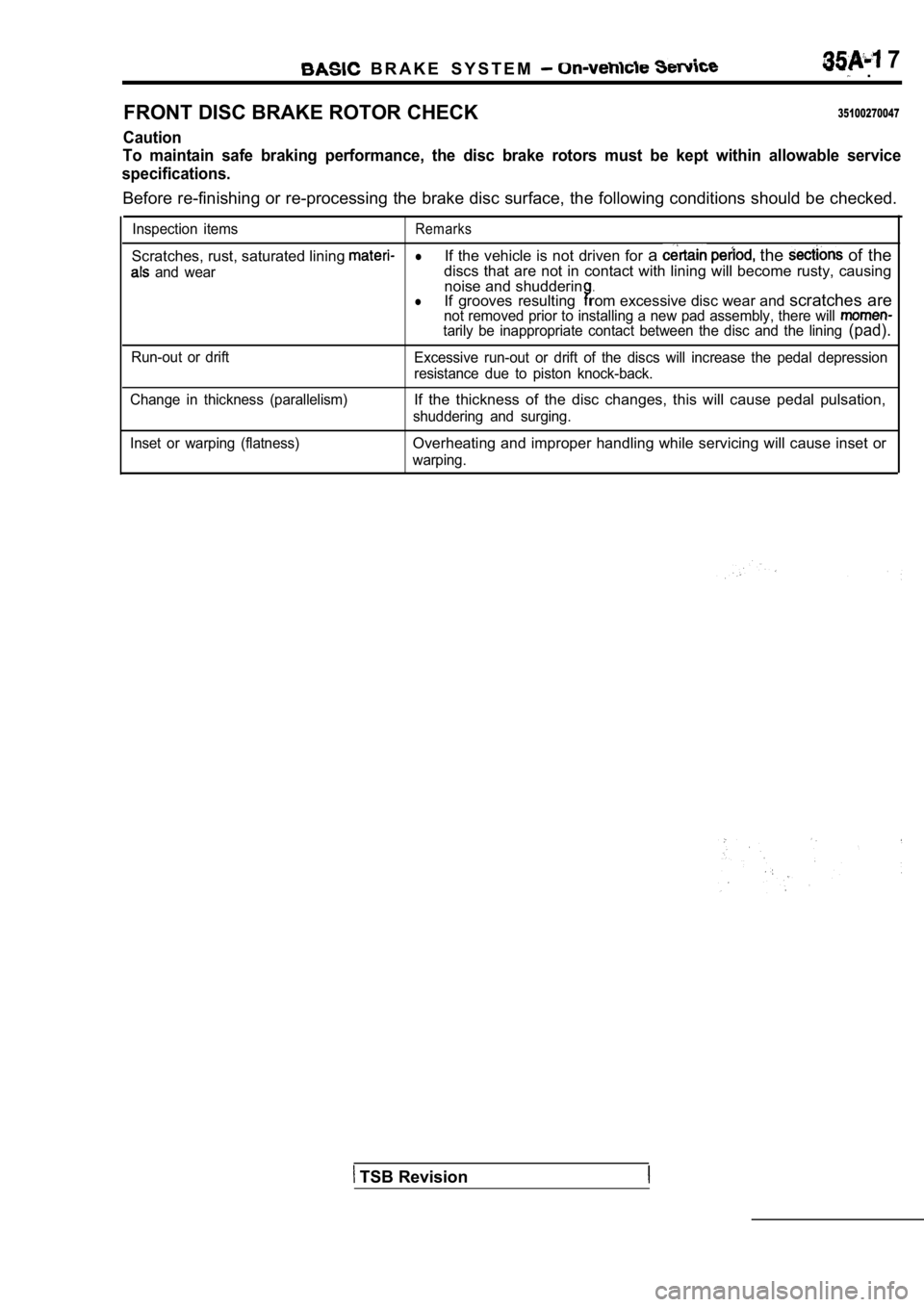
B R A K E S Y S T E M 7 .
FRONT DISC BRAKE ROTOR CHECK
35100270047
Caution
To maintain safe braking performance, the disc brak e rotors must be kept within allowable service
specifications.
Before re-finishing or re-processing the brake disc surface, the following conditions should be checke d.
Inspection itemsRemarks
Scratches, rust, saturated lining lIf the vehicle is not driven for a the of the
and weardiscs that are not in contact with lining will beco me rusty, causing
noise and shudderin.lIf grooves resultingrom excessive disc wear and scratches arenot removed prior to installing a new pad assembly, there will tarily be inappropriate contact between the disc and the lining (pad).
Run-out or drift
Excessive run-out or drift of the discs will increa se the pedal depression
resistance due to piston knock-back.
Change in thickness (parallelism)
If the thickness of the disc changes, this will cau se pedal pulsation,
shuddering and surging.
Inset or warping (flatness)
Overheating and improper handling while servicing w ill cause inset or
warping.
TSB Revision