1990 MITSUBISHI SPYDER check engine
[x] Cancel search: check enginePage 718 of 2103
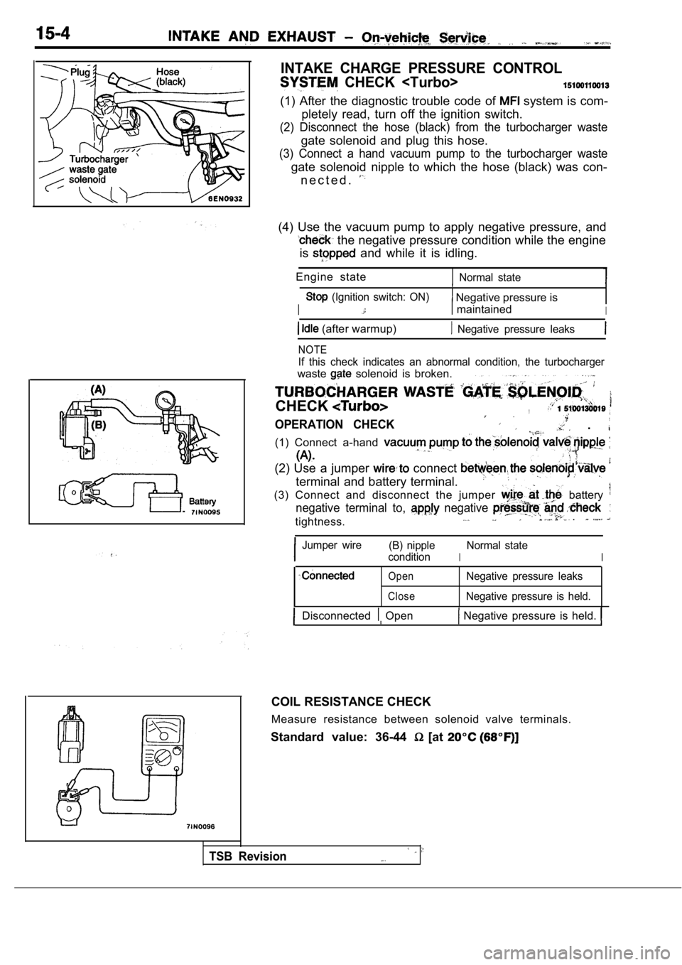
INTAKE CHARGE PRESSURE CONTROL
CHECK
(1) After the diagnostic trouble code of system is com-
pletely read, turn off the ignition switch.
(2) Disconnect the hose (black) from the turbocharg er waste
gate solenoid and plug this hose.
(3) Connect a hand vacuum pump to the turbocharger waste
gate solenoid nipple to which the hose (black) was con-
n e c t e d .
(4) Use the vacuum pump to apply negative pressure, and
the negative pressure condition while the engine
is
and while it is idling.
Engine state
Normal state
(Ignition switch: ON) Negative pressure is
I maintainedI
(after warmup) Negative pressure leaks
NOTE
If this check indicates an abnormal condition, the turbocharger
waste solenoid is broken.
CHECK,
OPERATION CHECK .
(1) Connect a-hand
(2) Use a jumper connect
terminal and battery terminal.
(3) Connect and disconnect the jumper
battery
negative terminal to, negative
tightness. .
Jumper wire (B) nipple
I
Normal state
condition
I
Open
CloseNegative pressure leaks
Negative pressure is held.
Disconnected Open Negative pressure is held.
COIL RESISTANCE CHECK
Measure resistance between solenoid valve terminals .
Standard value: 36-44
[at
TSB Revision
Page 727 of 2103
AND EXHAUST Intake Manifold
FUEL HOSE
Relieve pressure in line to prevent fuel outflow.
(Refer to GROUP
On-vehicle Service.)
Cautlon,
Cover fuel pipe line with shop after
sure as certain pressure may still
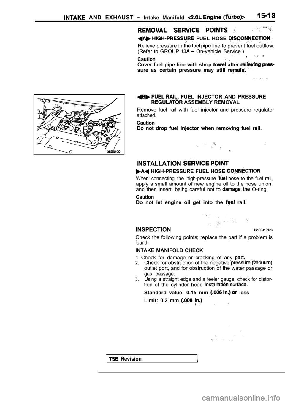
FUEL INJECTOR AND PRESSURE
ASSEMBLY REMOVAL
Remove fuel rail with fuel injector and pressure re gulator
attached.
Caution
Do not drop fuel injector when removing fuel rail.
INSTALLATION
HIGH-PRESSURE FUEL HOSE
When connecting the high-pressure hose to the fuel rail,
apply a small amount of new engine oil to the hose union,
and then insert, beihg careful not to
O-ring.
Caution
Do not let engine oil get into the rail.
INSPECTION15100310123
Check the following points; replace the part if a p roblem is
found.
INTAKE MANIFOLD CHECK
1. Check for damage or cracking of any
2.Check for obstruction of the negative
outlet port, and for obstruction of the water passa ge or
gas passage.
3.Using a straight edge and a feeler gauge, check for distor-
tion of the cylinder head
Standard value: 0.15 mm less
Limit: 0.2 mm
Revision
Page 730 of 2103
INTAKE AND EXHAUST Intake Manifold
REMOVAL SERVICE POINTS
HIGH-PRESSURE FUEL HOSE DISCONNECTION
Relieve pressure in the fuel pipe line to prevent fuel outflow.
(Refer to GROUP On-vehicle Service.)
Caution
Cover fuel pipe line with shop towel after relievin g pres-
sure as certain pressure may
remain.
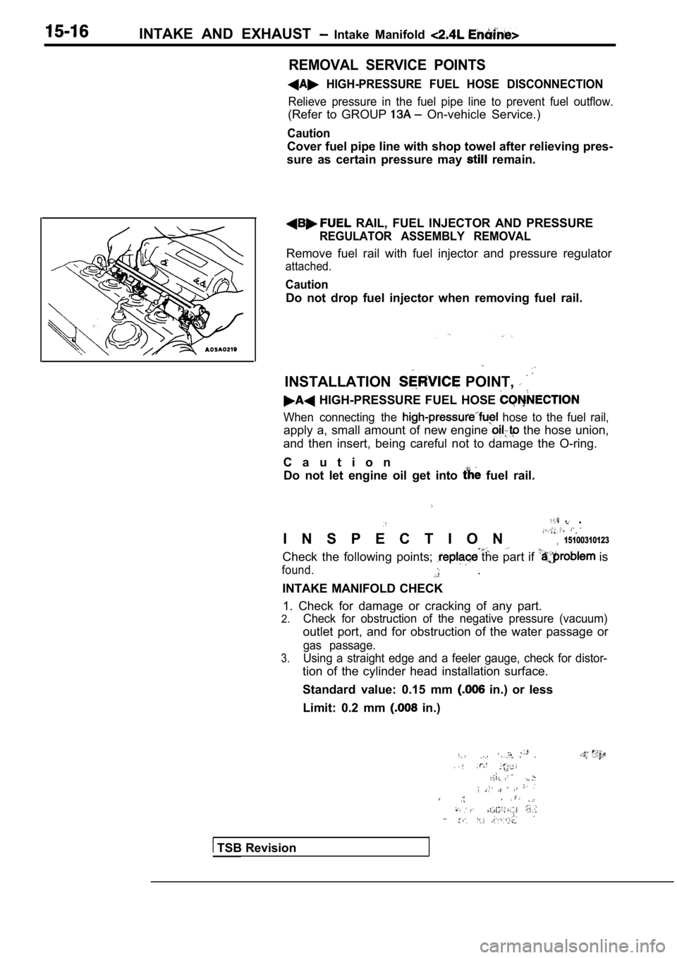
RAIL, FUEL INJECTOR AND PRESSURE
REGULATOR ASSEMBLY REMOVAL
Remove fuel rail with fuel injector and pressure re gulator
attached.
Caution
Do not drop fuel injector when removing fuel rail.
INSTALLATION POINT,
HIGH-PRESSURE FUEL HOSE
When connecting the hose to the fuel rail,
apply a, small amount of new engine the hose union,
and then insert, being careful not to damage the O- ring.
C a u t i o n Do not let engine oil get into
fuel rail.
.
I N S P E C T I O N 15100310123
Check the following points; the part if is
found. .
INTAKE MANIFOLD CHECK 1. Check for damage or cracking of any part.
2.Check for obstruction of the negative pressure (vac uum)
outlet port, and for obstruction of the water passage or
gas passage.
3.Using a straight edge and a feeler gauge, check for distor-
tion of the cylinder head installation surface.
Standard value: 0.15 mm
in.) or less
Limit: 0.2 mm
in.)
TSB Revision
Page 734 of 2103
INTAKE AND EXHAUST Exhaust Manifold ENGINE (Turbo)>
Identification holeExhaust
manifold
INSTALLATION SERVICE POINTS
TURBOCHARGER ASSEMBLY
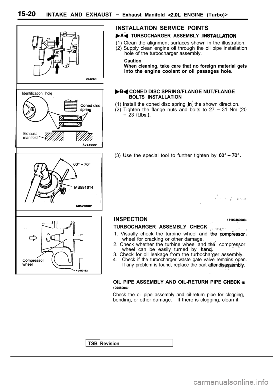
(1) Clean the alignment surfaces shown in the illus tration.
(2) Supply clean engine oil through the oil pipe in stallation
hole of the turbocharger assembly.
Caution
When cleaning, take care that no foreign material g ets
into the engine coolant or oil passages hole.
CONED DISC SPRING/FLANGE NUT/FLANGE
BOLTS INSTALLATION
(1) Install the coned disc spring the shown direction.
(2) Tighten the flange nuts and bolts to 27
31 Nm (20
23
(3) Use the special tool to further tighten by
INSPECTION
TURBOCHARGER ASSEMBLY CHECK . .
1. Visually check the turbine wheel and
wheel for cracking or other damage.
2. Check whether the turbine wheel and
compressor
wheel can be easily turned by
3. Check for oil leakage from the turbocharger asse mbly.
4.Check if the turbocharger waste gate valve remains open.
If any problem is found, replace the part
.
OIL PIPE ASSEMBLY AND OIL-RETURN PIPE
Check the oil pipe assembly and oil-return pipe for clogging,
bending, or other damage. If there is clogging, clea n it.
TSB Revision
Page 741 of 2103

CONTENTS
AUTO-CRUISE CONTROL SYSTEM
. . . . . . . . . . . . . . . . . . . . . . . . . . . . . . . . . . . . .7
AUTO-CRUISE CONTROL* . . . . . . . . . . . . . . 40
GENERAL INFORMATION . . . . . . . . . . . . . . . . 7
ON-VEHICLE SERVICE. . . . . . . . . . . . . . . . . 33
Auto-cruise Control Cable Check and
Adjustment . . . . . . . . . . . . . . . . . . . . . . . . . . . . . .
33
Auto-cruise Control Component Check . . . . . 37
Auto-cruise Control System Operation Check
. . . . . . . . . . . . . . . . . . . . . . . . . . . . . . . . . . . . . . . . .
35
SERVICE SPECIFICATIONS . . . . . . . . . . . . . 8
SPECIAL TOOLS . . . . . . . . . . . . . . . . . . . . . . . . 8
TROUBLESHOOTING
ENGINE (NON-TURBO)> . . . . . . . . . . . 9
TROUBLESHOOTING
(TURBO) AND ENGINE> . . . . .
EMISSION CONTROL’ SYSTEM
. . . . .
CATALYTIC . . . . . . . . . . . . . .
General Information . . . . . . . . . . . . . . . . . . 57
EVAPORATIVE EMISSION .
SYSTEM. . . . . . . . . . . . . . . .
Air Conditioning . . . . . . . . . . . . . . . . . . . 52
Component Location
. . . . . . . . . . . . . . . . . .
Engine Coolant Temperature Sensor
Intake Air Temperature Sensor . . . . . . . . . . . . 52
WARNINGS REGARDING SERVICING OF SUPPLEMENTAL RESTRA INT SYSTEM (SRS) EQUIPPED
WARNING!
(1) Improper serviceor maintenance of any component of the or any SRS-related can to injuryorcleathtoservicepersonnel (from inadvertentfiring the SRS inoperative).
(2) Service or maintenance of any SRS component or SRS-related component must be performed only
MITSUBISHI dealer.
(3) MITSUBISHI dealer personnel must thoroughly rev iew this manual, and especially its GROUP
Restraint System (SRS) and GROUP 00 Maintenance Service, before any service or maintenance of any
componentof the SRS or any SRS-related component.
NOTEJhe includes the following components: warning light, air bag module, clock components (that may have to be removed/installed in connection with or areIndicated in the table of contents by an asterisk
Page 742 of 2103
17-2
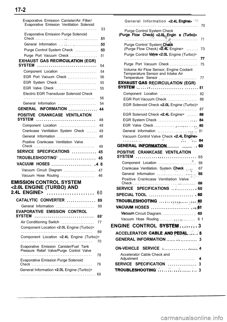
Evaporative Emission Canister/Air Filter/
Evaporative Emission Ventilation Solenoid
. . . . . . . . . . . . . . . . . . . . . . . . . . . . . . . . . . . . . . . . .53
Evaporative Emission Purge Solenoid
Check. . . . . . . . . . . . . . . . .. . . . . . . . . . . . . . . . . . .
General Information. . .. . .. . . . . . . . . . . . . . .
Purge Control System Check. . . . . . . . . . . . .
Purge Port Vacuum Check. . . . . . . . . . . . . . . .51
EXHAUST GAS (EGR)
SYSTEM. . . . . . . . . . . . . . . . . . . . . . . . . . . . . . . 54
Component Location. . . . . . . . . . . . . . . . . . . . .54
EGR Port Vacuum Check. . . . . . . . . . . . . . . . .56
EGR System Check. . . . . . . . . . . . . . . . . . . . . .55
EGR Valve Check. . . . . . . . . . . . . . . . . . . . . . . .55
Electric EGR Transducer Solenoid Check
. . . . . . . . . . . . . . . . . . . . . . . . . . . . . . . . . . . . . . . . .
56
General Information. . . . . . . . . . . . . . . . . . . . . .54
GENERAL INFORMATION. . . . . . . . . . . . . . .44
POSITIVE CRANKCASE VENTILATION
SYSTEM. . . . . . . . . . . . . . . . . . . . . . . . . . . . . . . 48
Component Location. . . . . . . . . . . . . . . . . . . . .48
Crankcase Ventilation System Check. . . . . .49
General Information. . . . . . . . . . . . . . . . . . . . . .48
Positive Crankcase Ventilation Valve
Check. . . . . . . . . . . . . . . . . . . . . . . . . . . . . . . . . . .49
SERVICE SPECIFICATIONS. . . . . . . . . . . . .45
TROUBLESHOOTING’
. . . . . . . . . . . . . . . . . . .45
VACUUM HOSES. . . . . . . . . . . . . . . . . . . . . ..4 8
Vacuum Circuit Diagram. . . . . . . . . . . . . . . . . .47
Vacuum Hose Routing
. . . . . . . . . . . . . . . . . . . .46
CONTROL SYSTEM
ENGINE (TURBO) AND
ENGINE>. . . . . . . . . . . . . . . . . . . . . 6 0
CATALYTIC CONVERTER. . . . . . . . . . . . . . .89
General Information. . . . . . . . . . . . . . . . . . . . . .89
EVAPORATIVE EMISSION CONTROL
SYSTEM. . . . . . . . . . . . . . . . . . . . . . . . . . . . . . .69’
Air Conditioning Switch
. . . . . . . . . . . . . . . . . . .77
Component Location Engine (Turbo)>
. . . . . . . . . . . . . . . . . . . . . . . . . . . . . . . . . . . . . . . . .
69
Component Location Engine (Turbo)>
. . . . . . . . . . . . . . . . . . . . . . . . . . . . . . . . . . . . . . . . .
70
Evaporative Emission Canister/Fuel Tank
Pressure Relief Valve/Purge Control Valve
. . . . . . . . . . . . . . . . . . . . . . . . . . . . . . . . . . . . . . . . .78
Evaporative Emission Purge Solenoid
Check. . . . . . . . . . . . . . . . . . . . . . . . . . . . . . . . . . .76
General Information Engine (Turbo)> G e n e r a l I n f o r m a t i o n
. . . . . . . . . . . . . . . . . .
. . . . . . . . . . . . . . . . . . . . . . .70
Purge Control System Check
. . . . . . . . . . . . . . . . . . . . . . . . . .. . . . . . . . . . . . . . . .71
Purge Control ‘System
(Purge Flow Check) Engine>. . . . . . .73
Purge Control Engine (Turbo)>
. . . . . . . . . . . . . . . . . . . . . . . . . . . . . . . . . . . . . . . . . .
Purge Port Vacuum Check. . . . . . . . . . . . . . . .75
Volume Air Flow Sensor, Engine Coolant
Temperature Sensor and Intake Air
Temperature Sensor. . . . . . . . . . . . . . . . . . . . . . .77
RECIRCULATION (EGR)
.... . .. . . . . . . . . . . . . . . . . . . . . . . .81
Component Location. . . . . . . . . . . . . . . . . . . . .82
EGR Port Vacuum Check . . . . . . . . . . . . . . . . .86
EGR Solenoid Check Engine (Turbo)>
. . . . . . . . . . . . . . . . . . . . . . . . . . . . . . . . . . . . . . . . .
87
EGR Solenoid Check Engine>. . . . . .
EGR System Check . . . . . . . . . . . . . . . . . .
EGR Valve Check. . . . . . . . . . . . .. . .
General Information... . . . . . . . . . . . . .....81
Vacuum Control Valve Check
. . . . . . . . .
.......................................
POSITIVE CRANKCASE VENTILATION
SYSTEM
. . . . . . . ... . .. . . . . . . . . . . . . . . . . 65
Component Location. . . . . . . . . . . . .. . . . . . . . .66
Crankcase Ventilation. System . .67
General Information
. . . .. . . . . ... . ........
Positive Crankcase Ventilation Valve
Check. . . . . . . . . . . . . . . . . . . . . ... . ............
SERVICE SPECIFICATIONS. .. . . . . . . . . 60
SPECIAL TOOL . . . . . . . . . . . . . . . . . . . . . . .
. . .. .
HOSES
. . . . ..
. . . . . . . . . . . . . . . . . . . . .,
Circuit Diagram.. . . . . . . . . . . . . . . . . . ,
Vacuum Hose Routing. . . . . . . ...... . . . 6 1
ENGINE CONTROL
3
ACCELERATOR
......
GENERAL INFORMATION . . . . . .. . . . . . . . . .3
ON-VEHICLE SERVICE. . . . . . . . . . . .4
Accelerator Cable Check and
Adjustment. . . . . . . . . . . . . . . . . . . . . . . . . . . . . . .
SERVICE SPECIFICATION. . . . . . . . . . . . . . .3
. ... . . . . ...3. . . . . . . . . . . . . . . . . . . . . . . . . . . . . . . . . . . . . . . . .
69
Page 744 of 2103
ENGINE AND EMISSION CONTROL Engine Control
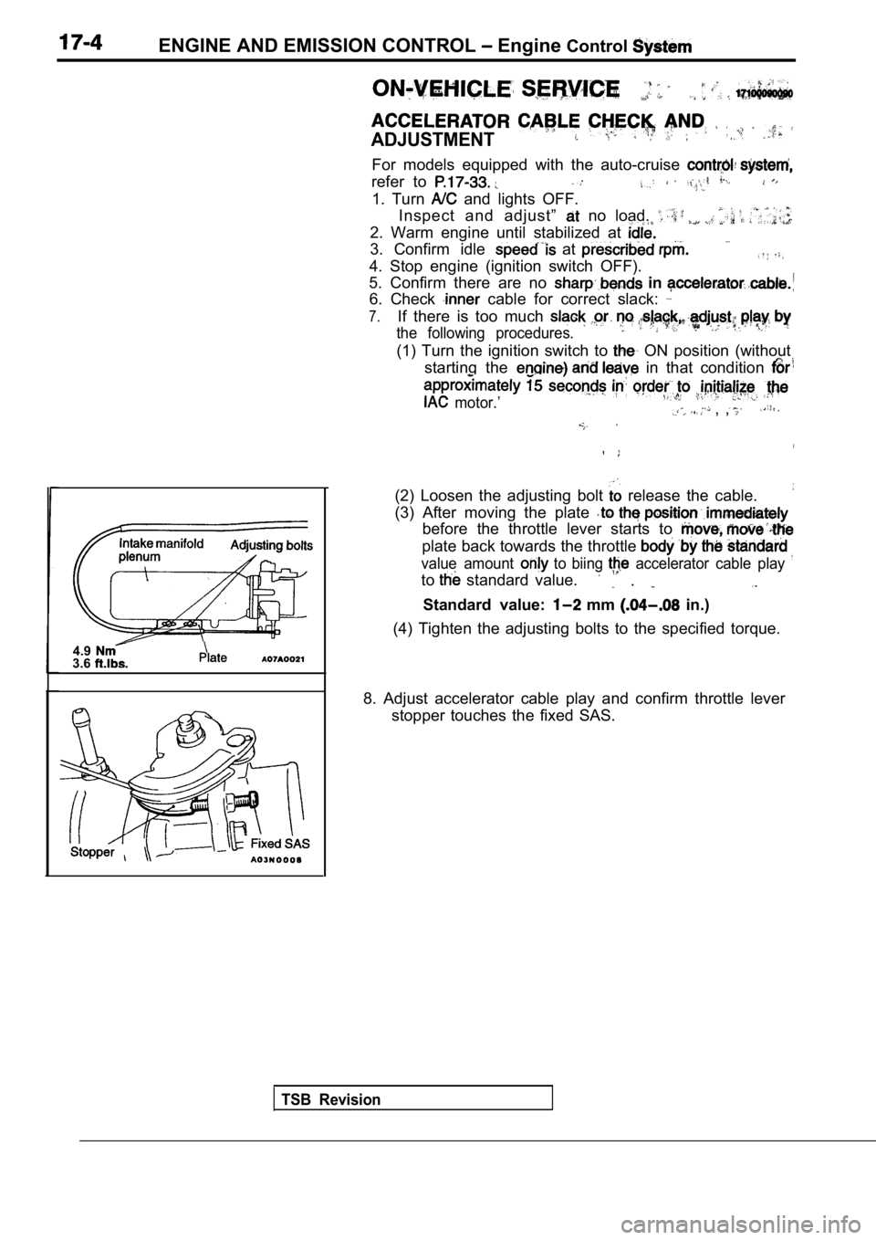
ADJUSTMENT
For models equipped with the auto-cruise
refer to
1. Turn and lights OFF.
Inspect and adjust”
no load.
2. Warm engine until stabilized at
3. Confirm idle at
4. Stop engine (ignition switch OFF).
5. Confirm there are no in
6. Check cable for correct slack:
7.If there is too much
the following procedures.
(1) Turn the ignition switch to ON position (without
starting the
in that condition
motor.’ , ,
4.93.6
TSB Revision
(2) Loosen the adjusting bolt release the cable.
(3) After moving the plate
before the throttle lever starts to
plate back towards the throttle
value amount to biing accelerator cable play
to standard value. .
Standard value: mm in.)
(4) Tighten the adjusting bolts to the specified to rque.
8. Adjust accelerator cable play and confirm thrott le lever
stopper touches the fixed SAS.
Page 748 of 2103
E N G I N E A N D E M I S S I O N C O N T R O L .
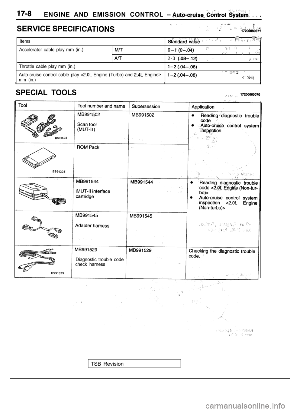
SERVICE
,
Items .
Accelerator cable play mm (in.)
2 - 3
Throttle cable play mm (in.)
Auto-cruise control cable play Engine (Turbo) and Engine>
mm (in.)
SPECIAL TOOLS
MUT-II
Diagnostic trouble code
check harness
TSB Revision