Page 670 of 2103

( T U R B O )
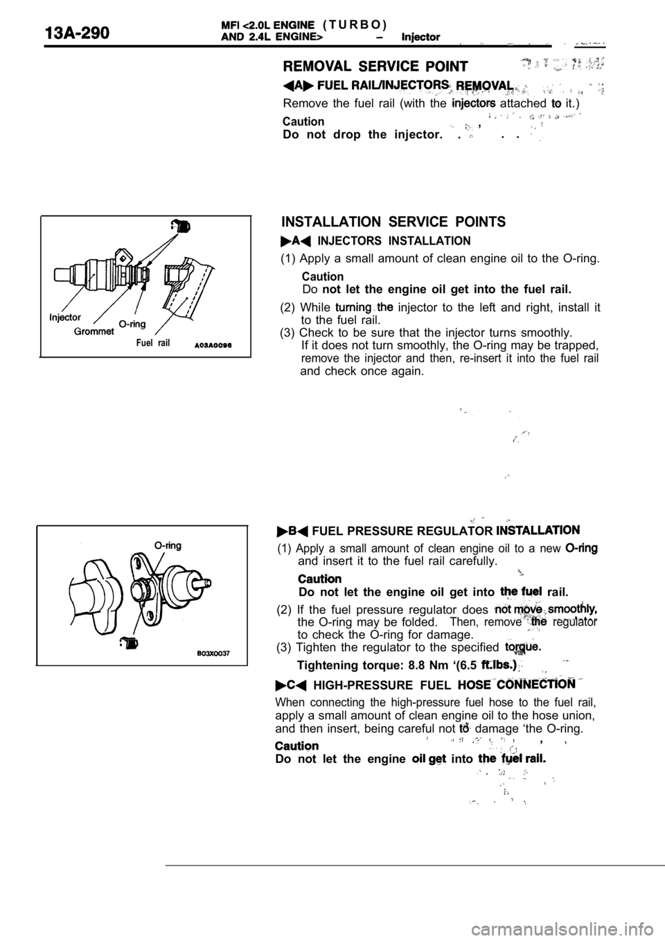
Remove the fuel rail (with the attached it.)
Caution ,
Do not drop the injector.
. . .
Fuel rail
INSTALLATION SERVICE POINTS
INJECTORS INSTALLATION
(1) Apply a small amount of clean engine oil to the O-ring.
Caution
Donot let the engine oil get into the fuel rail.
(2) While
injector to the left and right, install it
to the fuel rail.
(3) Check to be sure that the injector turns smooth ly.
If it does not turn smoothly, the O-ring may be tra pped,
remove the injector and then, re-insert it into the fuel rail
and check once again.
FUEL PRESSURE REGULATOR
(1) Apply a small amount of clean engine oil to a n ew
and insert it to the fuel rail carefully.
Do not let the engine oil get into rail.
(2) If the fuel pressure regulator does
the O-ring may be folded.Then, remove regulator
to check the O-ring for damage.
(3) Tighten the regulator to the specified
Tightening torque: 8.8 Nm ‘(6.5
HIGH-PRESSURE FUEL
When connecting the high-pressure fuel hose to the fuel rail,
apply a small amount of clean engine oil to the hose union,
and then insert, being careful not
damage ‘the O-ring.,
Do not let the engine into
,
Page 685 of 2103
FUEL SUPPLY Fuel Tank
Valve closed
Valve opened
Toport A To
INSPECTION
FUEL TANK FILLER TUBE
Engine (Non-turbo)
(1) Connect a clean rubber hose to the port
tank filler tube assembly.
(2) Blow air into the hose. Check that the air flow s out of
the port B.
(3) Use a screwdriver or similartool to close the valve. Blow
air into the hose in this condition. Check that the
not flow out of the port B.,
FUEL TANK DIFFERENTIAL PRESSURE SENSOR
CHECK
Engine>
(1) Disconnect the fuel tank differential
connector and connect the special tool
terminals of the disconnected connector.
(2) Turn the ignition switch to ON and take a readi ng of
the following output voltage. Between terminals (2)
(3)
Standard value: 2.0 3.0
FUEL CUT OFF VALVE CHECK
If the sound of the float valve moving (knocking so und) can
be heard when the valve assembly is gently shaken u p and
down, then the valve is okay.
FUEL GAUGE UNIT CHECKRefer to GROUP 54
Combination Meter.
TSB Revision
Page 691 of 2103

CONTENTS
GENERAL INFORMATION. . . . . . . . . . . . . . . . . .2SERVICE SPECIFICATIONS . . . . . . . . . . . . . . . . . 3
LUBRICANT3THERMOSTAT. . . . . . . . . . . . . . . . . . . . . . . . . . . .13. . . . . . . . . . . . . . . . . . . . . . . . . . . . . . .
ON-VEHICLE SERVICE. . . . . . . . . . . . . . . . . . . . .7TROUBLESHOOTING. . . . . . . . . . . . . . . . . . . . . . .4
Engine Coolant Concentration Test. . . . . . . . . . . .7.
Engine Coolant Leak Check . . . . . . . . . . . . . . . . . .
7WATER HOSE ‘AND PIPE
. . . . . . . . .
Engine Coolant Replacement. . . . . . . . . . . . . . . . .7 AND
Radiator Cap Valve Opening Pressure CheckENGINE>. . . . . . . . . . . . . . . .. . . . . . . . . . . . . . . . . .22
. . . . . . . . . . . . . . . . . . . . . . . . . . . . . . . . . . . . . . . . . . . . .7WATER PUMP
RADIATOR. . . . . . . . . .18. . . . . . . . . . . . . . . . . . . . . . . . . . . . . . . . .8 ENGINE (NON-TURBO)>
ENGINE (TURBO) AND , , S E A L A N T
. . . . . . . . . . . . . . . . . . . . . . . . . . . . . . . . . .3ENGINE>. . . . . . . . . . . . . . . . . . . . . . . . . . . . . . .18
Page 695 of 2103
ENGINE COOLING Troubleshooting
TROUBLESHOOTING HINTS
Engine (Non-turbo)>
1. Only the radiator fan does not operate. l Check fusible link No. 7.
2. Only the condenser fan does not operate. l Check dedicated fuse No. 9.
3. The radiator fan and condenser fan do’ not operate in the low speed mode, but operate
otherwise.
4. The radiator fan and condenser fan do not
operate in the high speed mode, ‘but
otherwise.
lCheck the radiator fan motor relay and
condenser fan motor relay (HI).
l Check the power-train control module.
l Check the radiator fan motor relay (LO)
and condenser fan motor relay (LO).
l Check the powertrain control module.
Fan Operating Mode
.
TSB Revision
Page 696 of 2103
14-6ENGINE COOLING
Engine (Turbo) and Engine>
1. Only the radiator fan does not operate.
l Check fusible link No. 7.
2. Only the condenser fan does not operate.
l Check dedicated fuse No. 9.
3. The radiator fan and condenser fan do not operate in the low speed mode, but operate
otherwise.
l Check the radiator fan motor relay (LO)
and condenser fan motor relay (LO).
l Check the engine control module.
(Refer to GROUP Troubleshooting.)
I -* I.
4. The radiator fan and fan do not
Fan Operating Mode operate in the high speed mode, but
lCheck the, radiator’ fan motor
fan ,
lCheck en
(Refer to,
.
Air conditioning switch
OFF
OFF
OFF
ON
ON
TSB Revision
Page 697 of 2103

ENGINE COOLING On-vehicle Service
Engine (Turbo) and
ON-VEHICLE SERVICE
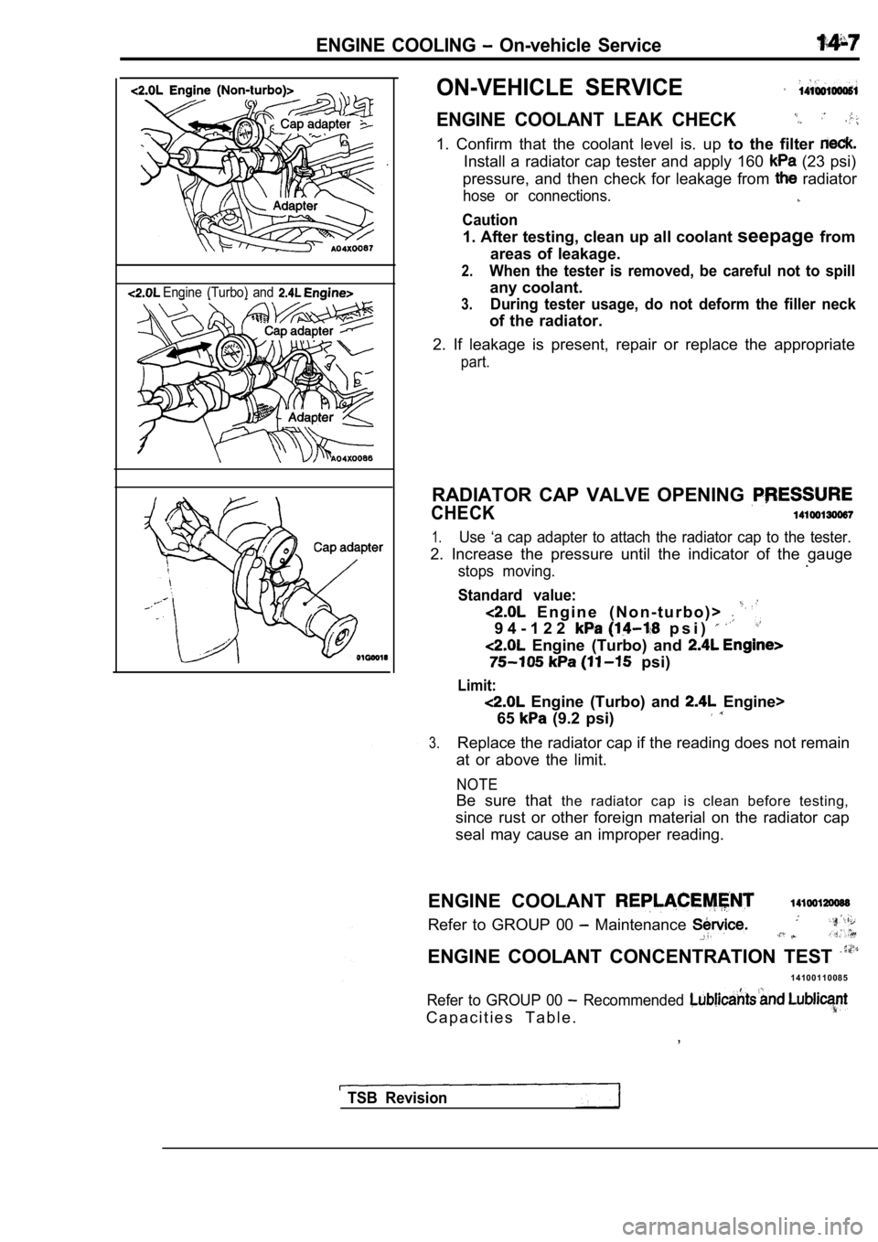
ENGINE COOLANT LEAK CHECK
1. Confirm that the coolant level is. up to the filter
Install a radiator cap tester and apply 160 (23 psi)
pressure, and then check for leakage from
radiator
hose or connections.
Caution
1. After testing, clean up all coolant seepagefrom
areas of leakage.
2.When the tester is removed, be careful not to spill
any coolant.
3.During tester usage, do not deform the filler neck
of the radiator.
2. If leakage is present, repair or replace the app ropriate
part.
RADIATOR CAP VALVE OPENING
CHECK
1.Use ‘a cap adapter to attach the radiator cap to the tester.
2. Increase the pressure until the indicator of the gauge
stops moving..
Standard value:
E n g i n e ( N o n - t u r b o ) >
9 4 - 1 2 2 p s i )
Engine (Turbo) and
psi)
Limit:
Engine (Turbo) and Engine>
65
(9.2 psi)
3.Replace the radiator cap if the reading does not re main
at or above the limit.
NOTE
Be sure that the radiator cap is clean before testing,
since rust or other foreign material on the radiato r cap
seal may cause an improper reading.
ENGINE COOLANT
Refer to GROUP 00 Maintenance
ENGINE COOLANT CONCENTRATION TEST
1 4 1 0 0 1 1 0 0 8 5
Refer to GROUP 00 Recommended
C a p a c i t i e s T a b l e . ,
TSB Revision
Page 699 of 2103
ENGINE
Engine (Turbo)>
Pre-removal OperationlEngine Coolant Draining (Refer to GROUP 00 Maintenance Service.)
Post-installation.
lEngine Coolant Supplying and GROUP 00 l A/T Fluid Checking and Refilling if with (Refer to GROUP 00 Maintenance
8.710
6
Radiator removal steps
1. Drain plug
2. Radiator cap
3. Overflow tube
4. Reserve tank 5. Reserve tank bracket
u p p e r h o s e 8. Radiator lower hose 9. Transaxle cooler hose and assembly
13. Condenser fan motor assembly
fan motor assembly
Radiator fan motor
17. Shroud
Radiator fan motor removal steps
Transaxle fluid hose and
pipe. with fan motor assembly
f a n 17.
.
.
TSB
Page 700 of 2103
ENGINE Radiator
Pm-removal Operationl Engine Coolant Draining(Refer to GROUP 00 Maintenance Service.)II
Post-installation OperationlEngine Coolant Supplying and GROUP 00 Maintenance l Fluid Checking -andRefilling Necessary with (Refer to GROUP 00 Maintenance
12 Nm8.7
Radiator removal steps
1. Drain plug
2. Radiator cap
3. Overflow tube
4. Reserve tank
5. Reserve tank bracket
8. Radiator upper hose 7. Radiator lower hose8. Transaxle fluid cooler hose and pipe assembly with 9. Upper insulator10. Radiator assembly11. Lower insulator
12. Condenser fan motor assembly
fan motor assembly
Radiator fan motor16. Shroud
12
Radiator fan steps
4.
8. Transaxle fluid ‘hose and with 13. fan
14..
.
TSB Revision