1990 MITSUBISHI SPYDER check engine
[x] Cancel search: check enginePage 608 of 2103
ENGINE (TURBO)
AND ENGINE> Troubleshooting
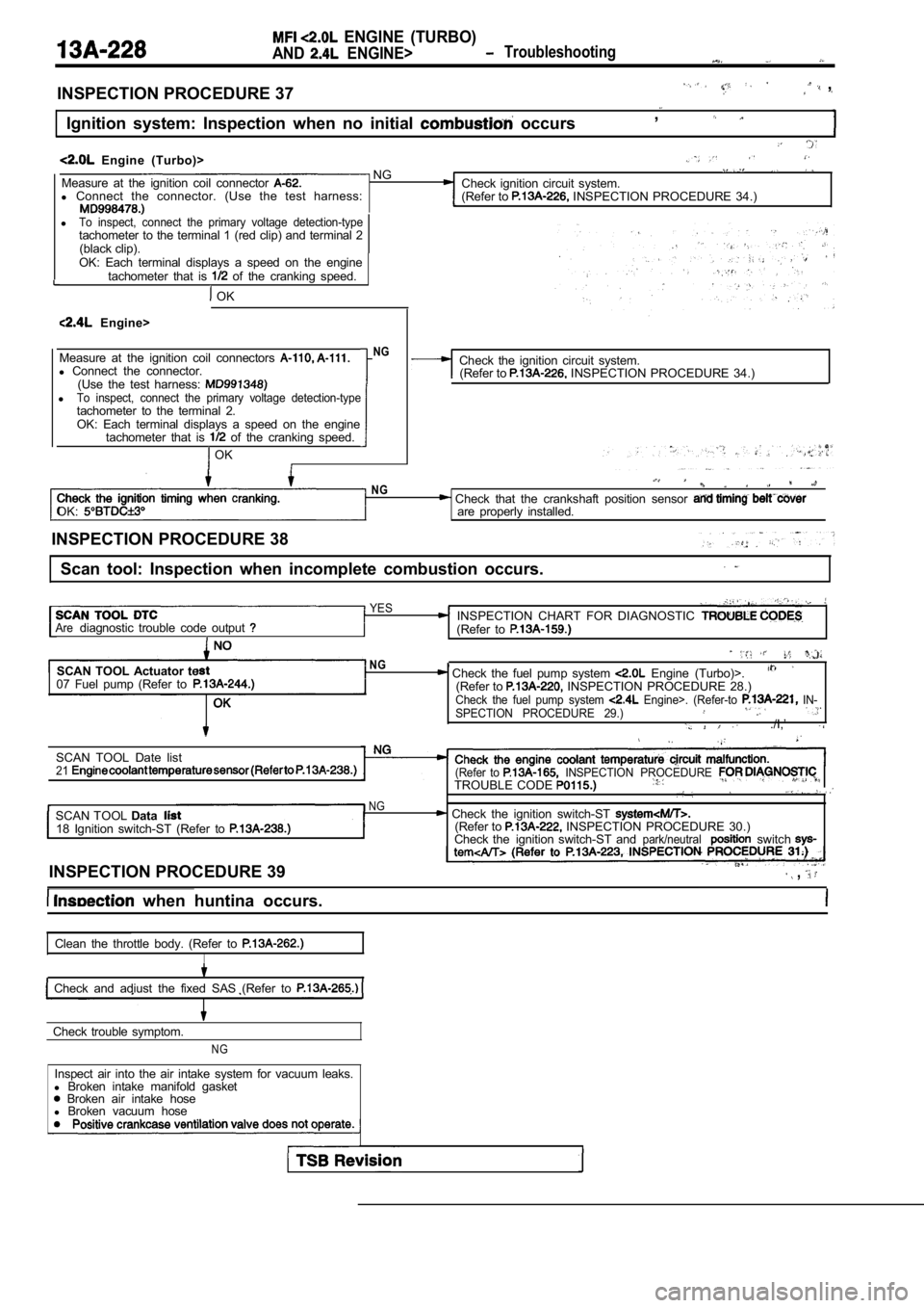
INSPECTION PROCEDURE 37 ,
Ignition system: Inspection when no initial occurs,
Engine (Turbo)> NGMeasure at the ignition coil connector Check ignition circuit system.
l Connect the connector. (Use the test harness:
(Refer to INSPECTION PROCEDURE 34.)
lTo inspect, connect the primary voltage detection-typetachometer to the terminal 1 (red clip) and terminal 2
(black clip).
OK: Each terminal displays a speed on the engine tachometer that is
of the cranking speed.
OK
Engine>
Measure at the ignition coil connectors
l Connect the connector.
(Use the test harness:
lTo inspect, connect the primary voltage detection-t ypetachometer to the terminal 2.OK: Each terminal displays a speed on the engine
tachometer that is of the cranking speed.
OK
NGCheck the ignition circuit system.(Refer to INSPECTION PROCEDURE 34.)
OK:
NG Check that the crankshaft position sensor are properly installed.
INSPECTION PROCEDURE 38
Scan tool: Inspection when incomplete combustion oc curs.
YESINSPECTION CHART FOR DIAGNOSTIC Arediagnostic trouble code output (Refer to
SCAN TOOL Actuator te
07 Fuel pump (Refer toNG, Check the fuel pump system Engine (Turbo)>.(Refer to INSPECTION PROCEDURE 28.)Check the fuel pump system Engine>. (Refer-to IN-
SPECTION PROCEDURE 29.)
./I,’
SCAN TOOL Date list21(Refer to INSPECTION PROCEDURE TROUBLE CODE
NGSCAN TOOL Data Check the ignition switch-ST 18 Ignition switch-ST (Refer to (Refer to INSPECTION PROCEDURE 30.)
Check the ignition switch-ST andpark/neutralswitch
INSPECTION PROCEDURE 39 ,
when huntina occurs.
Clean the throttle body. (Refer to
I
Check and adiust the fixed SAS (Refer to
Check trouble symptom.
NG
Inspect air into the air intake system for vacuum l eaks.
l Broken intake manifold gasket
Broken air intake hose
l Broken vacuum hose
Page 609 of 2103
ENGINE (TURBO)
AND. ENGINE> Troubleshooting . ,
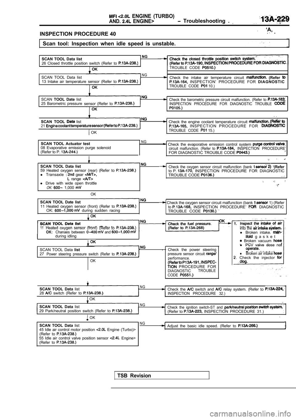
INSPECTION PROCEDURE 40
‘A, .
Scan tool: Inspection when idle speed is unstable.
SCAN TOOL Data list
NG
26 Closed throttle position switch (Refer to TROUBLE CODE
SCAN TOOL Data listNG Check the intake air temperature circuit (Refer 13 Intake air temperature sensor (Refer to INSPECTION’ PROCEDURE FOR DIAGNOSTICTROUBLE CODE 10.)
SCANTOOL Date listCheck the barometric pressure circuit malfunction. (Refer to 25 Barometric pressure
sensor (Refer toINSPECTION PROCEDURE FOR DIAGNOSTIC TROUBLE
.
SCAN TOOL list Check the engine coolant temperature circuit 21 I N S P E C T I O N P R O C E D U R E F O R
OKTROUBLE CODE 15.)
SCAN TOOL Actuator test
08 Evaporative emission purge solenoid
(Refer to P. NG Check the evaporative emission control system circuit malfunction. (Refer to INSPECTION PROCEDURE’FOR DIAGNOSTIC TROUBLE CODE
SCAN TOOL Data listNG
59 Heated oxygen sensor (rear) (Refer to l Transaxle gear range l Drive with wide open throttleOK: 1,000
OK
SCAN TOOL Date list11 Heated oxygen sensor (front) (Refer to OK: during sudden racing
Check the oxygen sensor circuit malfunction (bank ‘(Referto P. INSPECTION PROCEDURE FOR DIAGNOSTIC
TROUBLE CODE
Check the oxygen sensor circuit malfunction (bank 1) (Refer
to INSPECTION PROCEDURE’ DIAGNOSTIC
TROUBLE CODE
11Heated oxygen sensor (front) (Refer toOK:Chanaes between and during idlingI
SCAN TOOL Data listNG.
27
Power steering pressure switch (Refer to
OK
Check the power steeringpressure sensor circuit performance.
PROCEDURE FORDIAGNOSTIC TROUBLE
CODE
into the l Broken intake. g a s k e t Broken vacuum l PCV valve dose not
lBroken air intake 2. Check the injector
SCAN TOOL Data list
28 switch (Refer to
OK
N GCheck the switch and relay system. (Refer to INSPECTION PROCEDURE 32.)
SCAN TOOL Data listN G
29 Park/neutral position switch (Refer to Check the ignition switch-ST and (Refer to INSPECTION PROCEDURE 31.)
OK
SCAN TOOL Data list
45 Idle air control motor position Engine (Turbo)>
(Refer to
55 Idle air control valve position sensor Engine>
(Refer to
NGAdjust the basic idle speed. (Refer to
TSB Revision
Page 617 of 2103
ENGINE (TURBO)
AND
ENGINE> Troubleshooting
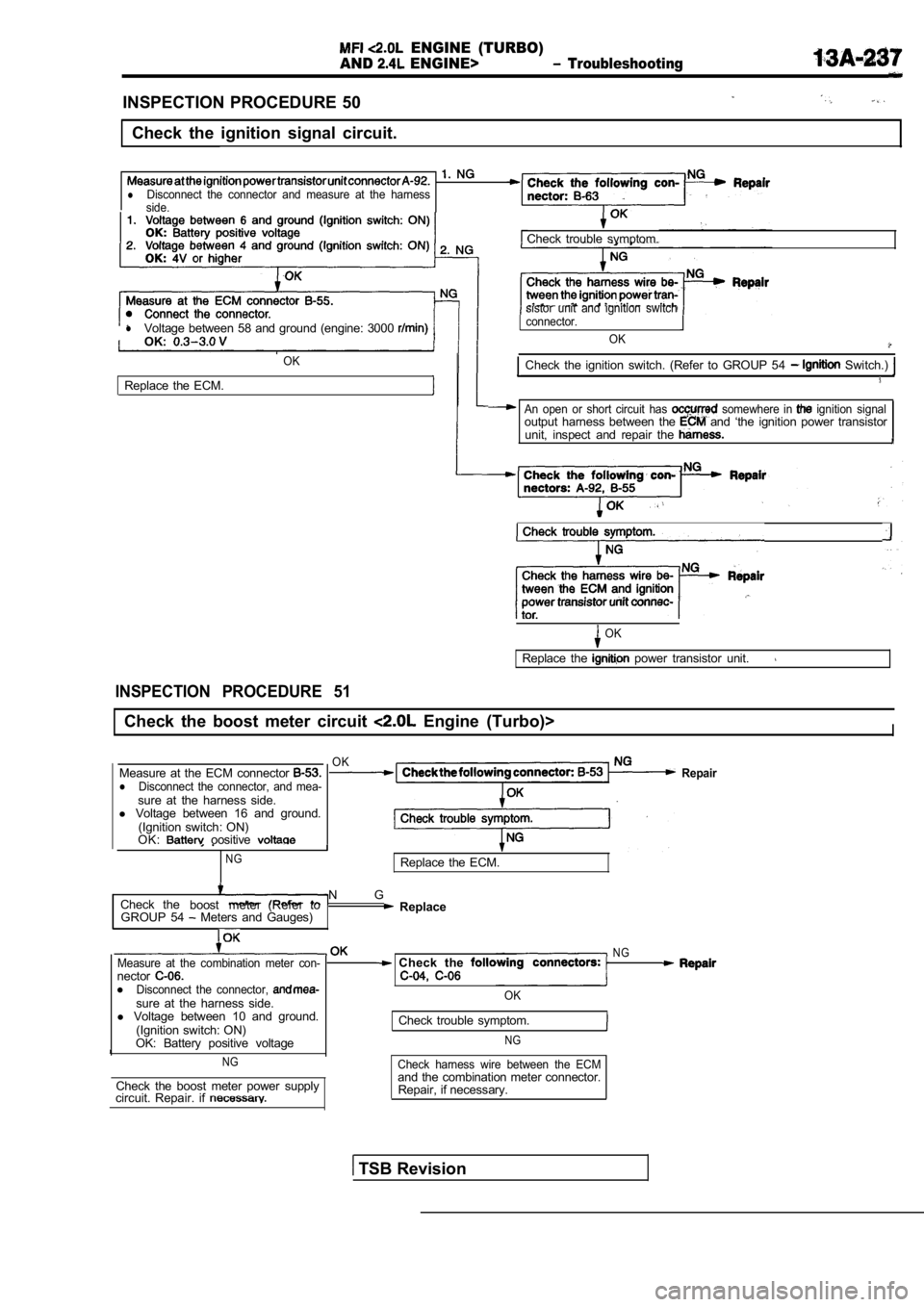
INSPECTION PROCEDURE 50
Check the ignition signal circuit.
lDisconnect the connector and measure at the harness
side.
lVoltage between 58 and ground (engine: 3000 OK:
OK
Replace the ECM. Check trouble symptom.
sistor unit and ignition switch
connector.
OK
Check the ignition switch. (Refer to GROUP 54 Switch.)
An open or short circuit has somewhere in ignition signaloutput harness between the and ‘the ignition power transistor
unit, inspect and repair the
Check trouble symptom.
OK
Replace the power transistor unit.
INSPECTION PROCEDURE 51
Check the boost meter circuit Engine (Turbo)>I
Measure at the ECM connector lDisconnect the connector, and mea-sure at the harness side.
l Voltage between 16 and ground.
(Ignition switch: ON)
OK:
oositive
NG
OKRepair
Replace the ECM.
Check the
boost meter (Refer to N G
GROUP 54 Meters and Gauges) Replace
Measure at the combination meter con-nectorlDisconnect the connector, sure at the harness side.
l Voltage between 10 and ground.
(Ignition switch: ON)
OK: Battery positive voltage
NG
Check the boost meter power supply
circuit. Repair. if
N G Check the
OK
Check trouble symptom.
NG
Check harness wire between the ECMand the combination meter connector.
Repair, if necessary.
TSB Revision
Page 619 of 2103
ENGINE (TURBO)
AND ENGINE>
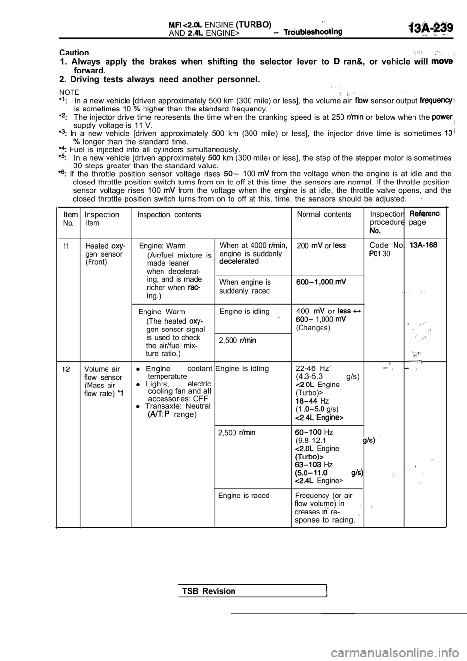
Caution
1. Always apply the brakes when shifting the select or lever to ran&, or vehicle will
forward.
2. Driving tests always need another personnel.
NOTE
In a new vehicle [driven approximately 500 km (300 mile) or less], the volume air sensor output
is sometimes 10 higher than the standard frequency.
The injector drive time represents the time when the cranking speed is at 250 or below when the
supply voltage is 11 V.
In a new vehicle [driven approximately 500 km (300 mile) or less], the injector drive time is sometimes
longer than the standard time.
Fuel is injected into all cylinders simultaneously.
In a new vehicle [driven approximately km (300 mile) or less], the step of the stepper mo tor is sometimes
30 steps greater than the standard value.
If the throttle position sensor voltage rises 100 from the voltage when the engine is at idle and th e
closed throttle position switch turns from on to of f at this time, the sensors are normal. If the throttle position
sensor voltage rises 100
from the voltage when the engine is at idle, the t hrottle valve opens, and the
closed throttle position switch turns from on to of f at this, time, the sensors should be adjusted.
Item Inspection
No.item
Inspection contents Normal contentsInspection
procedure page
11HeatedEngine: WarmWhen at 4000 200 or Code No.
gen sensor engine is suddenly(Air/fuel mixture is 30
(Front)
made leaner
when decelerat- ing, and is made
richer when
When engine is
suddenly raceding.)
Engine: Warm Engine is idling
400 or
(The heated 1,000 ,gen sensor signal(Changes)
is used to check
2,500
the air/fuel mix-
ture ratio.)
Volume airl Engine coolant Engine is idling 22-46 Hz’
flow sensortemperature(4.3-5.3 g/s)
(Mass airl
Lights,electric
flow rate) cooling fan and all Engine
accessories: OFF(Turbo)>
l Transaxle: Neutral Hz
range)(1 g/s)
2,500
Engine is raced
Hz
(9.8-12.1
Engine,
Hz ,
Engine>
Frequency (or air
flow volume) in
creases
re- ,
sponse to racing.
TSB Revision
Page 622 of 2103
E N G I N E
AND ENGINE>. . .
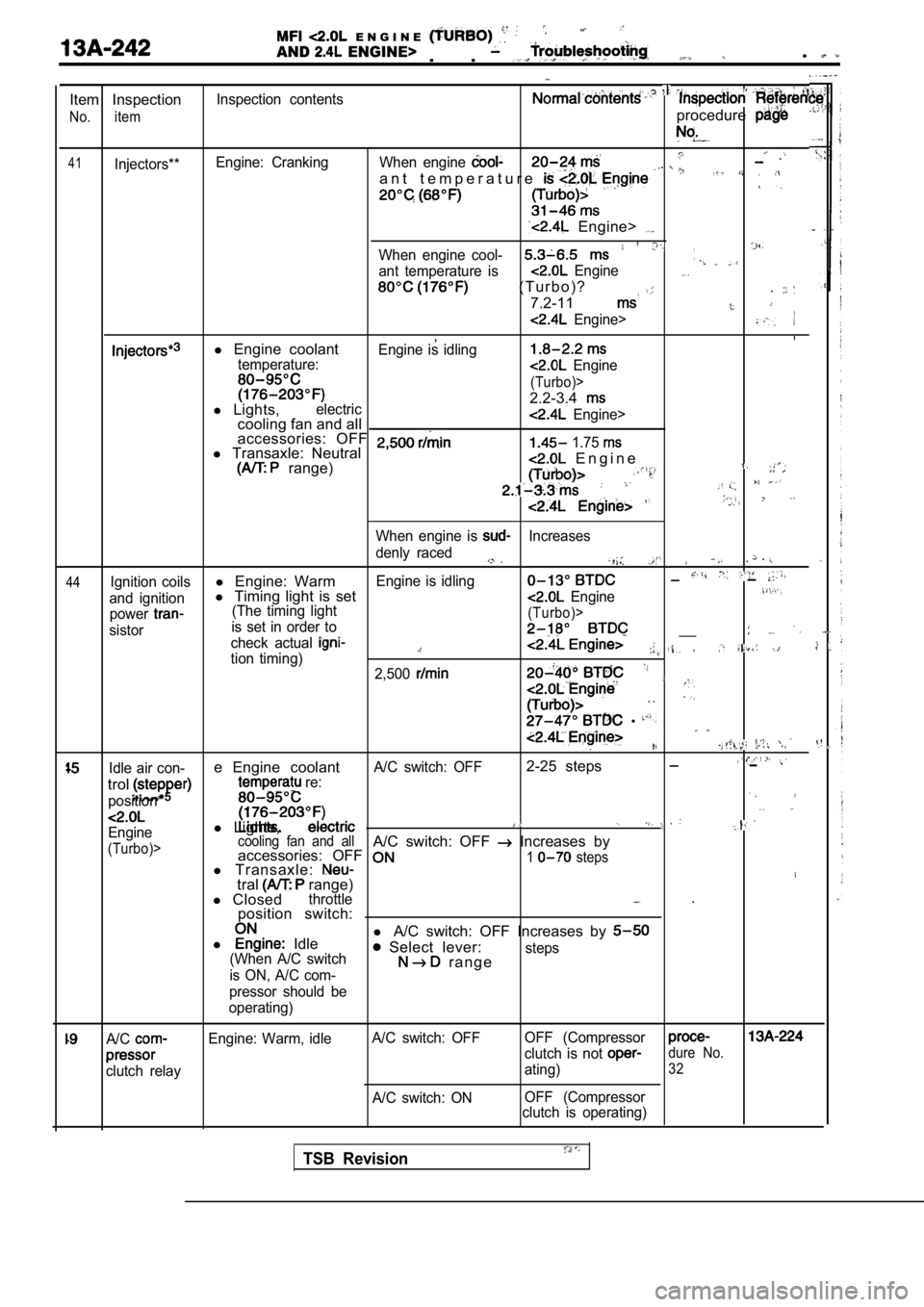
Item Inspection
No. item
41Injectors**Inspection contents
Engine: Cranking
procedure
When engine
a n t t e m p e r a t u r e
Engine>
When engine cool-
ant temperature is Engine
( T u r b o ) ?
7.2-11
.
Engine>
,l Engine coolantEngine is idlingtemperature: Engine
(Turbo)>
2.2-3.4l Lights,electriccooling fan and all Engine>
accessories: OFF l Transaxle: Neutral 1.75
range) E n g i n e
44
When engine is Increases
denly raced
.
Ignition coilsl Engine: WarmEngine is idling
and ignitionl Timing light is set Engine
power(The timing light
sistor is set in order to(Turbo)>
check actual __
tion timing)2,500
. .
.
,
Idle air con-e Engine coolantA/C switch: OFF2-25 steps
trol
position*
re:
l
Lights,Engine
(Turbo)> cooling fan and allA/C switch: OFF Increases by
accessories: OFF
l Transaxle:1 steps
tral range)
l Closedthrottle .
position switch:
l
Idle l
A/C switch: OFF Increases by Select lever:(When A/C switch
is ON, A/C com- r a n g esteps
pressor should be
operating)
A/C
clutch relay Engine: Warm, idle
A/C switch: OFF
A/C switch: ON OFF (Compressor
clutch is not dure No.
ating)32
OFF (Compressor
clutch is operating)
TSB Revision
Page 624 of 2103
ENGINE (TURBO)
AND
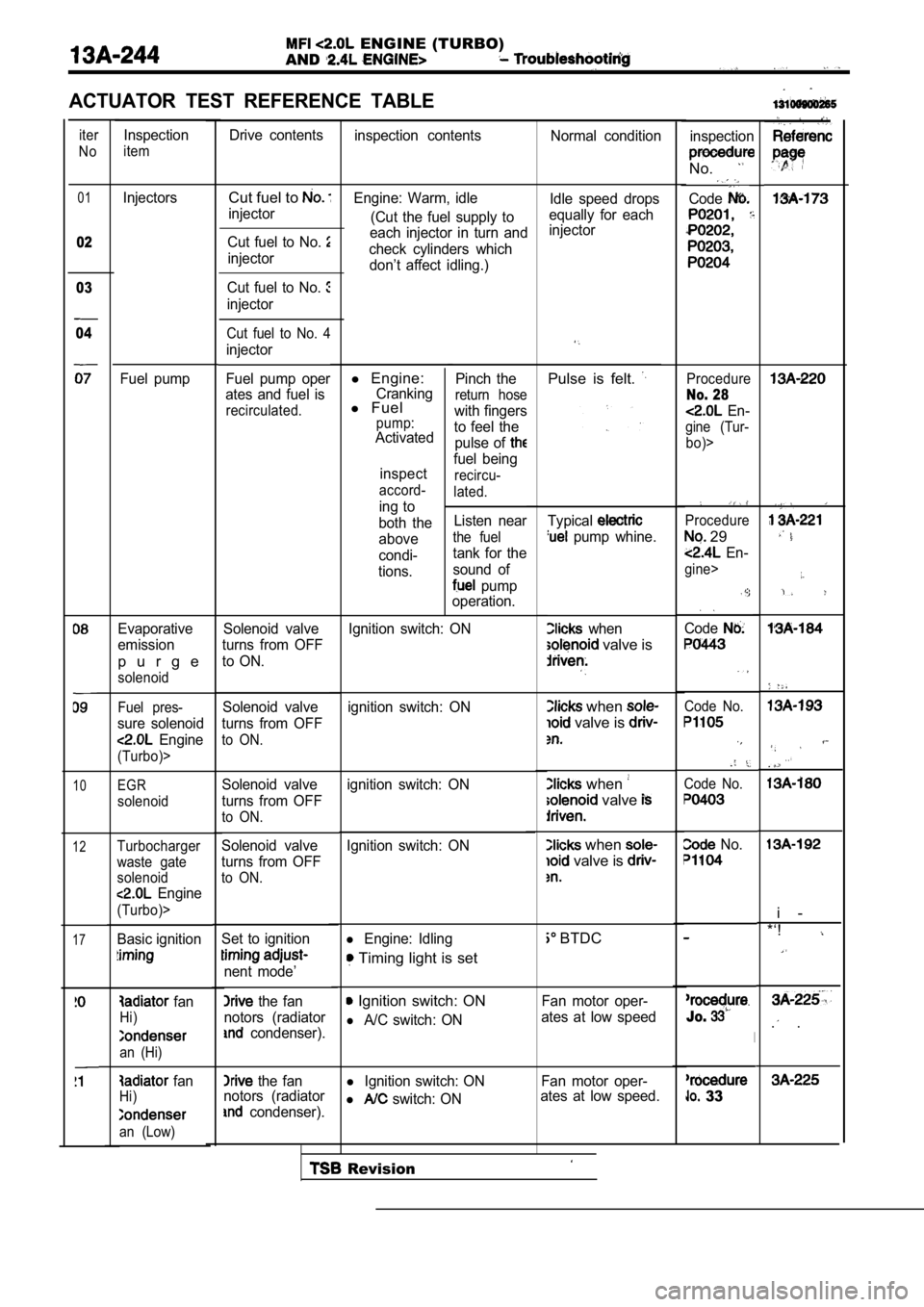
ACTUATOR TEST REFERENCE TABLE
iter
NoDrive contents inspection contents Normal condition
Inspection
iteminspection
No.
Code01
02
Cut fuel to
injector Idle speed drops
equally for each
injector
Engine: Warm, idle
(Cut the fuel supply to
each injector in turn and
check cylinders which don’t affect idling.)
l Engine:Crankingl Fuelpump:Activated
inspect
accord-
ing to
both the
above
condi-
tions. Pinch the
return hose
with fingers
to feel the pulse of
fuel being
recircu-
lated.
Listen near
the fuel
tank for the
sound of
pump
operation.
Injectors
Fuel pump Cut fuel to No.
injector
03
04
Cut fuel to No.
injector
Cut fuel to No. 4
injector
Fuel pump oper
ates and fuel is
recirculated.
Pulse is felt. Procedure
No. 28
En-
gine (Tur-
bo)>
Typical
pump whine.
when
valve is
Procedure
29
En-
gine>
Code
when
valve is
when
valve
Code No.
Code No.
when
valve is
No.
BTDC
Fan motor oper-
ates at low speed
Jo.
l Ignition switch: ON Fan motor oper-
l switch: ON ates at low speed. 33
Evaporative
emission
p u r g e
solenoid
Solenoid valve
turns from OFF
to ON.
. .
i -
*‘!
. .
Ignition switch: ON
Fuel pres-
sure solenoid
Engine
(Turbo)>
ignition switch: ON
Solenoid valve
turns from OFF
to ON.
10EGR
solenoid
ignition switch: ON
Solenoid valve
turns from OFF
to ON.
Solenoid valve
turns from OFF
to ON.
12Ignition switch: ONTurbocharger
waste gate
solenoid
Engine
(Turbo)>
Basic ignitionl Engine: Idling
Timing light is set
17Set to ignition
nent mode’
the fan
notors (radiator
condenser).
Ignition switch: ON
l A/C switch: ON
fan
Hi)
an (Hi)
the fan
notors (radiator
condenser).
fanHi)
an (Low)
Revision
Page 625 of 2103
ENGINE (TURBO)
AND Troubleshooting ,
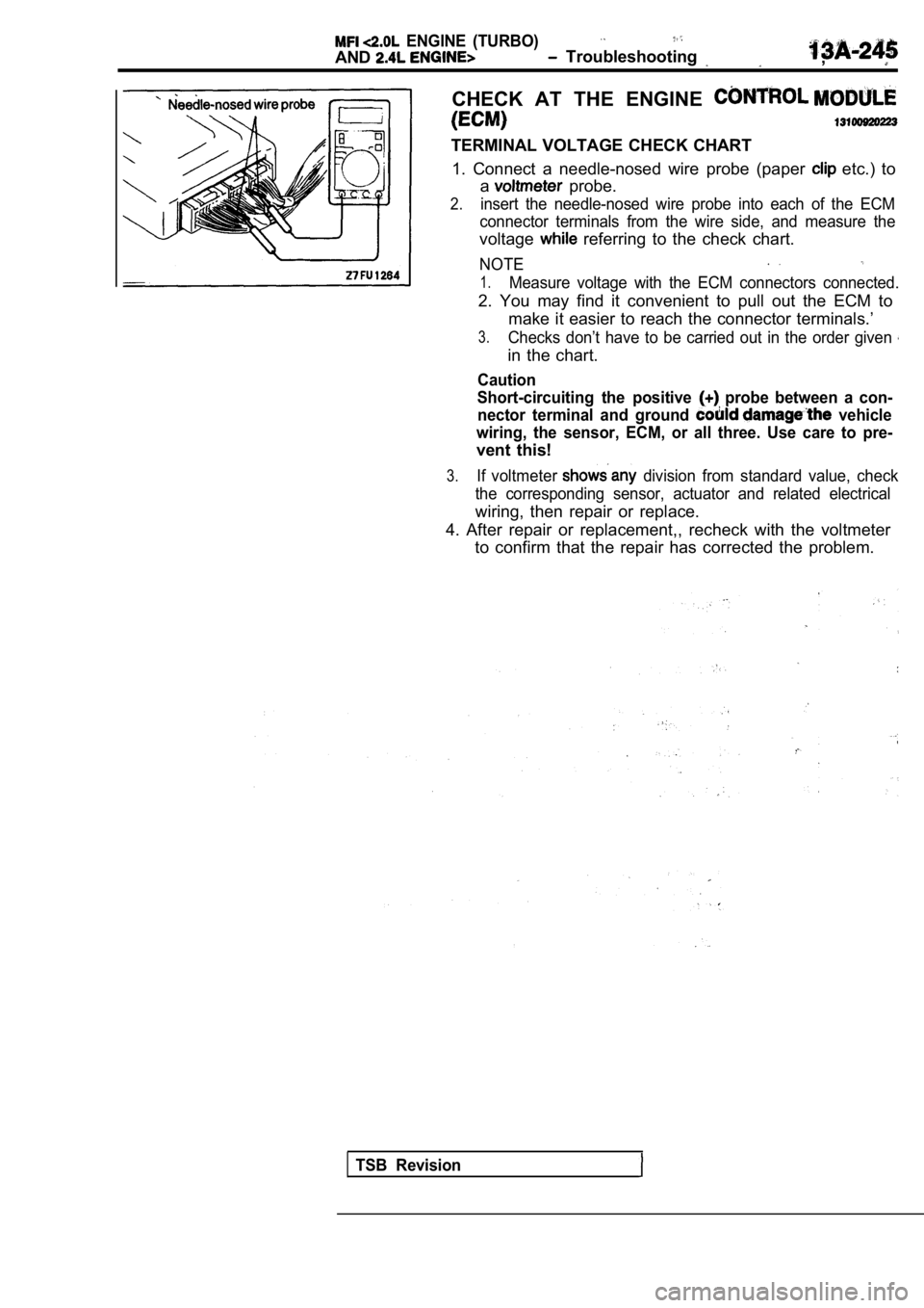
CHECK AT THE ENGINE
TERMINAL VOLTAGE CHECK CHART1. Connect a needle-nosed wire probe (paper
etc.) to
a
probe.
2.insert the needle-nosed wire probe into each of the ECM
connector terminals from the wire side, and measure the
voltage referring to the check chart.
NOTE
1.Measure voltage with the ECM connectors connected.
2. You may find it convenient to pull out the ECM to
make it easier to reach the connector terminals.’
3.Checks don’t have to be carried out in the order gi ven
in the chart.
Caution
Short-circuiting the positive
probe between a con-
nector terminal and ground
vehicle
wiring, the sensor, ECM, or all three. Use care to pre-
vent this!
3.If voltmeter division from standard value, check
the corresponding sensor, actuator and related elec trical
wiring, then repair or replace.
4. After repair or replacement,, recheck with the v oltmeter
to confirm that the repair has corrected the proble m.
TSB Revision
Page 626 of 2103
E N G I N E
AND ENGINE>
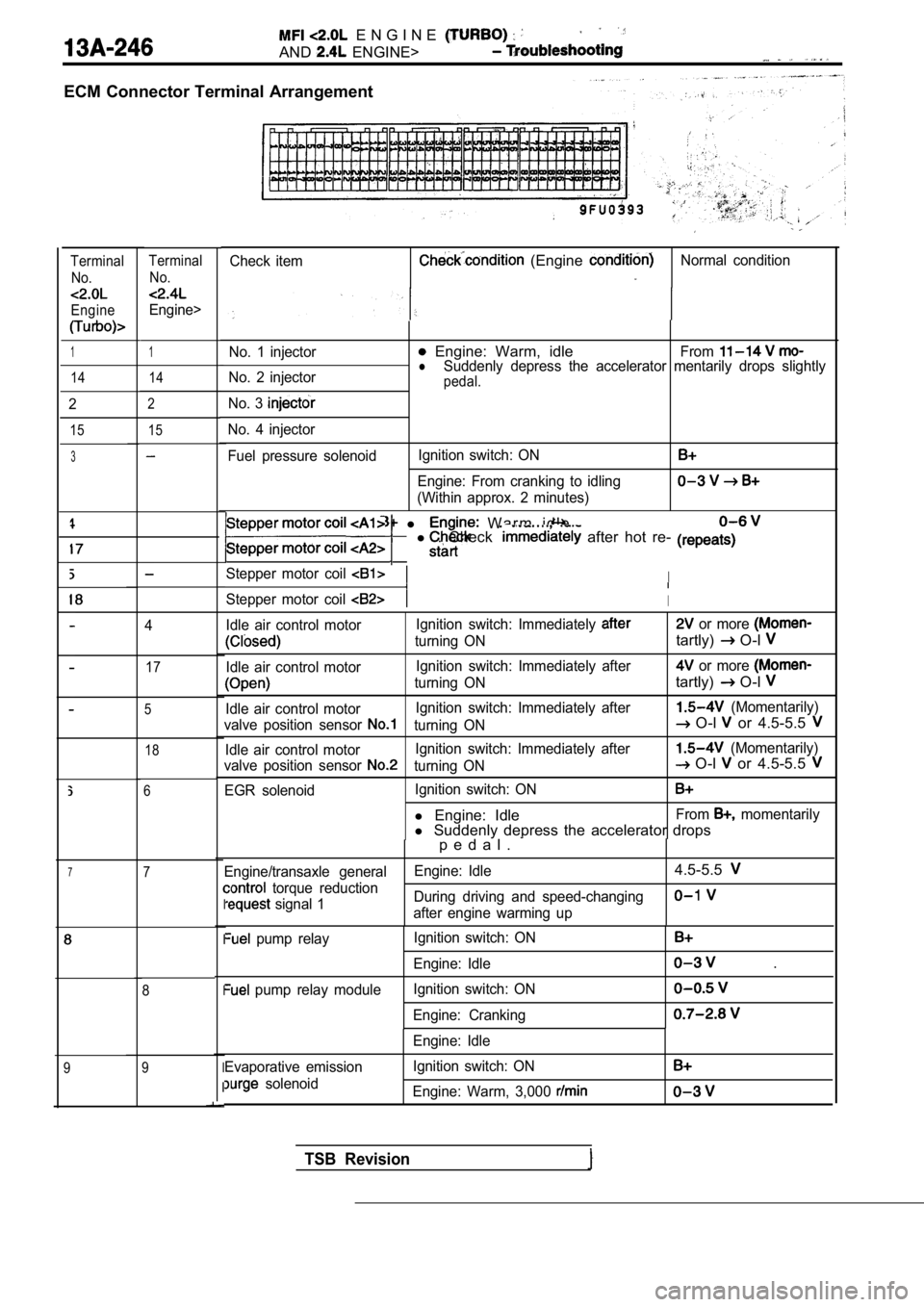
ECM Connector Terminal Arrangement
Check item (Engine Normal conditionTerminalNo.
Engine
TerminalNo.
Engine>
1No. 1 injector Engine: Warm, idleFromlNo. 2 injector Suddenly depress the accelerator mentarily drops sl
ightlypedal.
No. 3
No. 4 injector
Fuel pressure solenoidIgnition switch: ON
Engine: From cranking to idling
(Within approx. 2 minutes)
1
14 14
2
15
2
15
3
l W a r m i d l e
l . Check after hot re-
Stepper motor coil I
Stepper motor coil I
Idle air control motor Ignition switch: Immediately or more
turning ONtartly) O-l
Idle air control motorIgnition switch: Immediately after or more
turning ONtartly) O-l
Idle air control motorIgnition switch: Immediately after (Momentarily)
valve position sensor
turning ON O-l or 4.5-5.5
Idle air control motor Ignition switch: Immediately after (Momentarily)
valve position sensor
turning ON O-l or 4.5-5.5
EGR solenoid Ignition switch: ON
l
Engine: IdleFrom momentarily
l Suddenly depress the accelerator drops
4
17
5
18
6
p e d a l .
Engine/transaxle general Engine: Idle4.5-5.5
torque reduction
signal 1During driving and speed-changingafter engine warming upI
I
I
I
I
pump relay
pump relay module Ignition switch: ON
Engine: Idle
Ignition switch: ON
Engine: Cranking
.
Evaporative emission
solenoid Engine: Idle
Ignition switch: ON
Engine: Warm, 3,000
77
8
9
9
TSB Revision