Page 656 of 2103
Name
Air conditioning compressor clutch relay
Air conditioning switchSymbol Name
air control motor
coil power transistor)
Camshaft position sensor
Check engine/Malfunction indicator lamp
Crankshaft position sensor
Data link connectorIgnition power transistor
injector
Manifold differential pressure sensor
EGR solenoid fuel relavI I
Engine control module (ECM)
Engine coolant temperature sensorPark/Neutral position switch
Power steering pressure switch
Evaporative emission purge solenoid
Fuel
check terminal
Throttle position sensor (with
throttle position switch)
Fuel pump relay
Fuel pump relay module
Heated oxygen sensor (Front)
Heated oxygen sensor (Rear)Vehicle speed sensor.
Vehicle speed sensor
Volume air flow sensor (with
temperature sensor and barometric pressure
sensor)
NOTE
The “Name” column is in alphabetical order.
Page 659 of 2103
neutralposition switch
I
Check engine/malfunction
indicator lamp
Dataconnector
o x v a e n,
(front)
.
Page 661 of 2103
COOLANT SENSOR
Caution
Be careful not to touch the tool against the
(resin section) when and
1.Remove engine coolant temperature sensor from the in-,
take manifold.
2.With temperature sensing portion of engine tem-
perature sensor immersed in hot water, check resist ance.
,
Temperature
(32)
20 (66)
40 (104)
60 (176)
Resistance
2.1-2.7
3.If the resistance deviates from the standard value greatly,
replace the sensor.
4. Apply sealant threaded-‘portion. ,
Specified sealant:
NUT locking Part No. 4171 or equivalent,
5. Install engine coolant temperature sensor
it to specified torque.
Sensor tightening torque: 30 Nm (22
6. Fasten harness connectors securely.
Page 663 of 2103

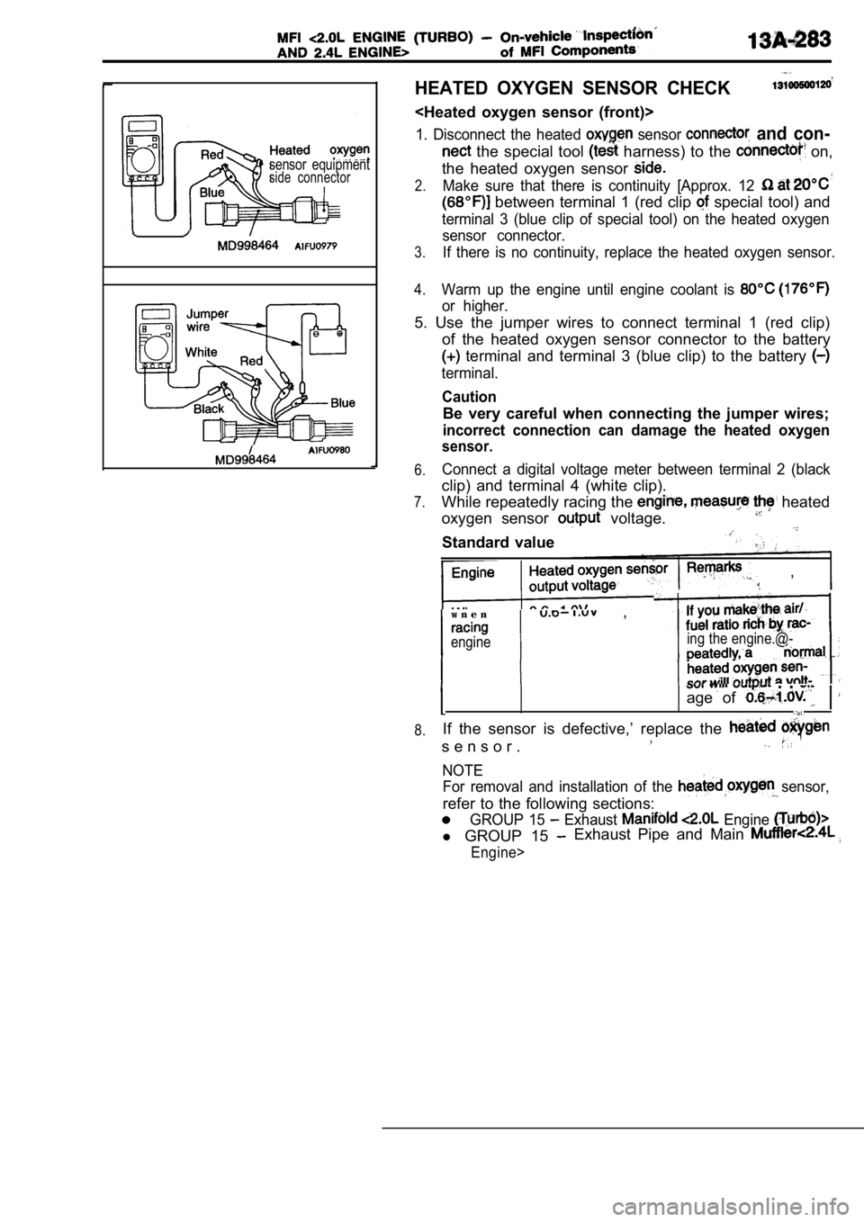
sensor equipmentside connector
HEATED OXYGEN SENSOR CHECK
1. Disconnect the heated sensor and con-
the special tool harness) to the on,
the heated oxygen sensor
2.Make sure that there is continuity [Approx. 12
between terminal 1 (red clip special tool) and
terminal 3 (blue clip of special tool) on the heate d oxygen
sensor connector.
3.If there is no continuity, replace the heated oxyge n sensor.
4.Warm up the engine until engine coolant is
or higher.
5. Use the jumper wires to connect terminal 1 (red clip)
of the heated oxygen sensor connector to the batter y
terminal and terminal 3 (blue clip) to the battery
terminal.
Caution
Be very careful when connecting the jumper wires;
incorrect connection can damage the heated oxygen
sensor.
6.
7.
8.Connect a digital voltage meter between terminal 2 (black
clip) and terminal 4 (white clip).
While repeatedly racing the
heated
oxygen sensor
voltage.
Standard value
,
w n e n ,
engineing the engine.@-
. .
age of
If the sensor is defective,’ replace the
s e n s o r .
NOTEFor removal and installation of the
sensor,
refer to the following sections:
GROUP 15 Exhaust Engine
l GROUP 15 Exhaust Pipe and Main
Engine>
Page 664 of 2103

ENGINE (TURBO)
ENGINE>of Components’
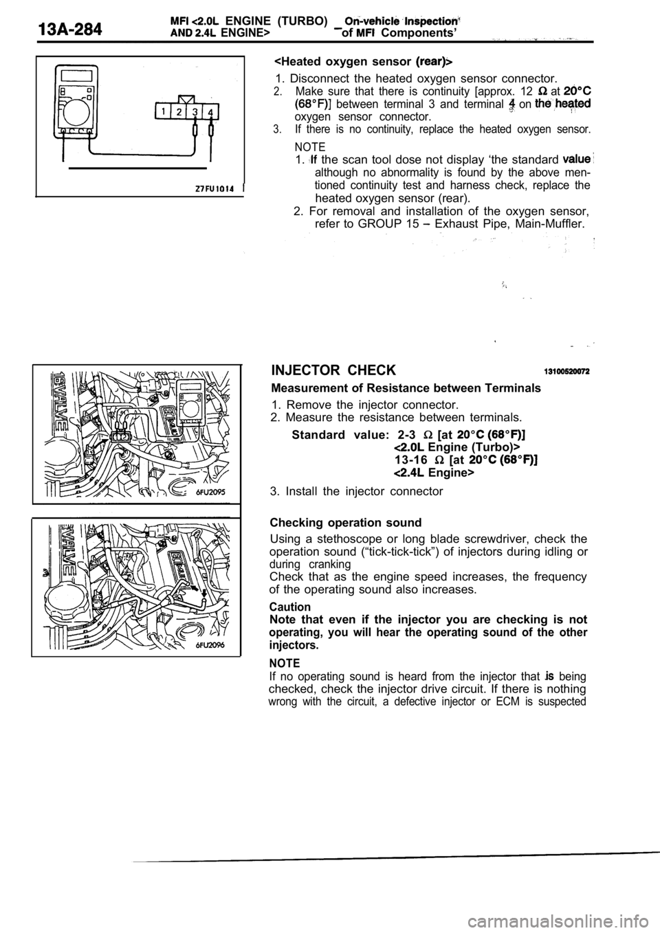
1. Disconnect the heated oxygen sensor connector.
2.Make sure that there is continuity [approx. 12 at
between terminal 3 and terminal on
oxygen sensor connector.
3.If there is no continuity, replace the heated oxyge n sensor.
NOTE
1. the scan tool dose not display ‘the standard
although no abnormality is found by the above men-
tioned continuity test and harness check, replace t he
heated oxygen sensor (rear).
2. For removal and installation of the oxygen senso r,
refer to GROUP 15
Exhaust Pipe, Main-Muffler.
INJECTOR CHECK
Measurement of Resistance between Terminals
1. Remove the injector connector.
2. Measure the resistance between terminals.
Standard value: 2-3
[at
Engine (Turbo)>
13-16
[at
Engine>
3. Install the injector connector
Checking operation sound Using a stethoscope or long blade screwdriver, chec k the
operation sound (“tick-tick-tick”) of injectors dur ing idling or
during cranking
Check that as the engine speed increases, the frequ ency
of the operating sound also increases.
Caution
Note that even if the injector you are checking is not
operating, you will hear the operating sound of the other
injectors.
NOTE
If no operating sound is heard from the injector th at being
checked, check the injector drive circuit. If there is nothing
wrong with the circuit, a defective injector or ECM is suspected
Page 665 of 2103
RESISTOR CHECK Engine (Turbo)>;
T e r m i n a l s
1. Disconnect the resistor connector.
2. Measure the resistance between terminals.
Measuring terminalsResistance
4-3
5-3
6-3
3.
If the resistance is out of specification, replace the resistor.
ai r
I D L E A I R MO T O R )
CHECK Engine (Turbo
1. Check to be sure that the engine coolant tempera ture
is
or below.
NOTE
Disconnecting the engine coolant temperature sensor
connector and connecting the harness-side of the co nnec-
tor to another engine coolant temperature sensor th at
is at
or below is also okay.
2. Check that the operation sound of the stepper mo tor
can be heard after the ignition is ON (but without
starting the motor), then
3.If the operation sound cannot be heard, check the
motor’s activation circuit.
If the circuit is normal, it is probable that there, is
tion of the stepper of the engine module.
Page 667 of 2103
IDLE AIR CONTROL (DC: MOTOR)
CHECK
Engine>
Use a stethoscope or long blade screwdriver to chec k if the
operating sound of the idle air control’ motor can
immediately after the ignition switch is turned to
NOTE
If the motor operation cannot be heard, check the m otor
drive circuit and the idle air control motor.
FUEL PRESSURE SOLENOID CHECK
Engine (Turbo)>
NOTE
When disconnecting the vacuum hose, always a mark’
so that it can be reconnected at original position! 1. Disconnect the vacuum hose from the solenoid val ve.
2. Disconnect the harness connector.
Page 668 of 2103
Connect a hand vacuum pump to the nipple.
Connect a battery to the solenoid valve and apply a vacu-
um to check air-tightness.
Battery voltage
Not applied
Applied nipple
Open
Closed
Open Normal condition
Vacuum leaks
Vacuum maintained
Vacuum maintained
Measure the resistance between the terminals of the sole-
noid valve.
Standard value: 36-44
[at
3.
4.
5.
EVAPORATIVE EMISSION PURGE SOLENOID
CHECK
Refer to GROUP 17 Emission Control System.
EGR SOLENOID CHECK13100570152
Refer to GROUP 17 Emission control System. Engine
(Turbo)>
Refer to GROUP 17 Emission Control System.
Engine>
WASTE GATE SOLENOID
Refer to GROUP 15 On-vehicle Service.