1990 MITSUBISHI SPYDER check engine
[x] Cancel search: check enginePage 749 of 2103

ENGINE AND EMISSION CONTROL Auto-cruise Control
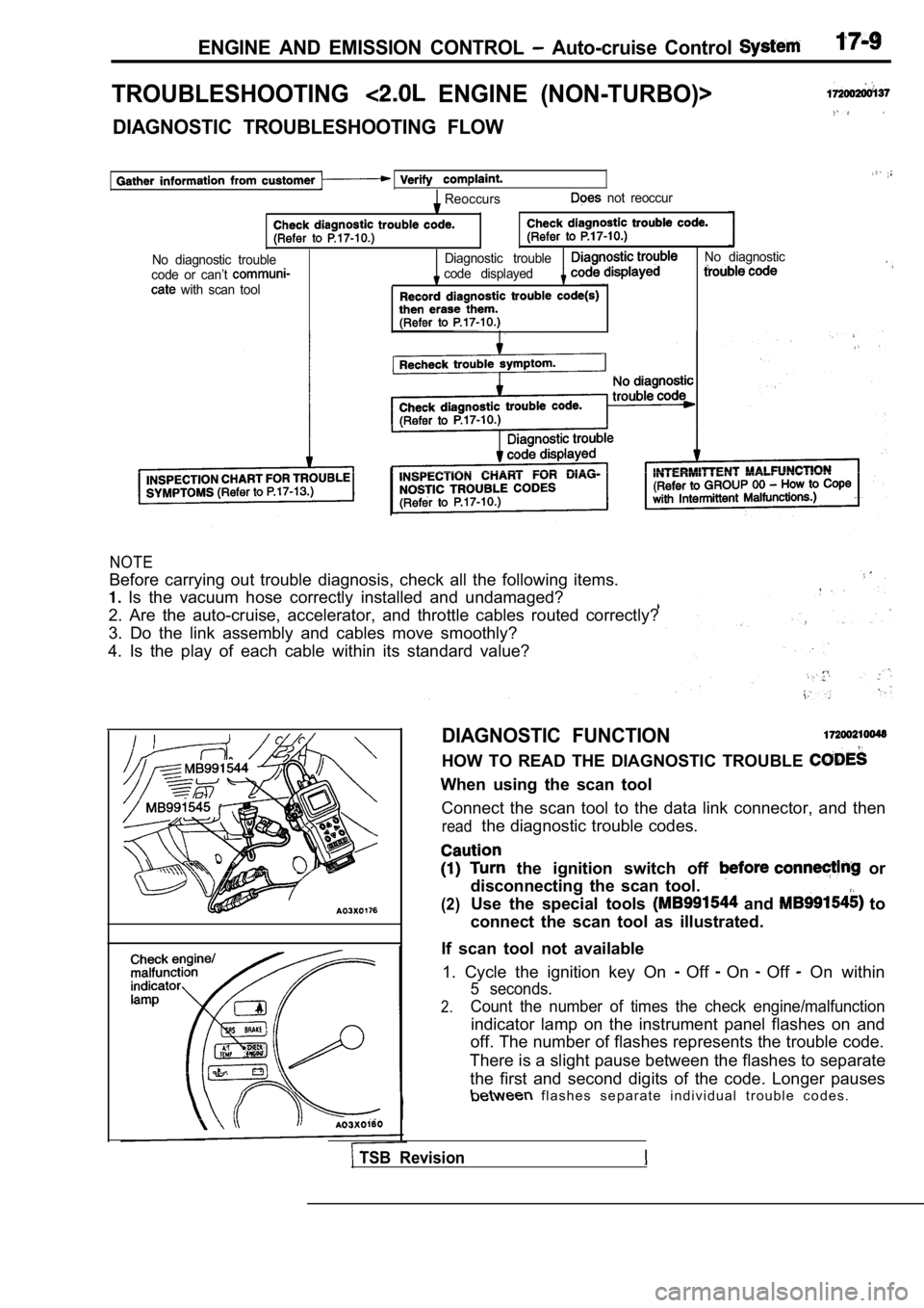
TROUBLESHOOTING ENGINE (NON-TURBO)>
DIAGNOSTIC TROUBLESHOOTING FLOW
Reoccurs not reoccur
No diagnostic troubleDiagnostic troubleNo diagnostic
code or can’t code displayed
with scan tool
NOTE
Before carrying out trouble diagnosis, check all th e following items.
Is the vacuum hose correctly installed and undamag ed?
2. Are the auto-cruise, accelerator, and throttle c ables routed correctly?
3. Do the link assembly and cables move smoothly?
4. Is the play of each cable within its standard va lue?
DIAGNOSTIC FUNCTION
HOW TO READ THE DIAGNOSTIC TROUBLE
When using the scan tool
Connect the scan tool to the data link connector, a nd then
readthe diagnostic trouble codes.
the ignition switch off or
disconnecting the scan tool.
(2)Use the special tools and to
connect the scan tool as illustrated.
If scan tool not available 1. Cycle the ignition key On
Off On Off On within
5 seconds.
2.Count the number of times the check engine/malfunct ion
indicator lamp on the instrument panel flashes on and
off. The number of flashes represents the trouble c ode.
There is a slight pause between the flashes to sepa rate
the first and second digits of the code. Longer pau ses
f l a s h e s s e p a r a t e i n d i v i d u a l t r o u b l e c o d e s .
TSB Revision
Page 750 of 2103

ENGINE AND EMISSION CONTROL Auto-cruise
ERASING DIAGNOSTIC TROUBLE CODES .
the scan tool
Connect the scan tool to the data link connector, then, erase the diagnostic trouble codes according
to scan tool instruction.
the scan tool
1. Remove the battery cable from the battery terminal for 10 seconds or more, then, reconnect
the cable.
2. After the engine has warmed up, run it at idle f or about 15 minutes.
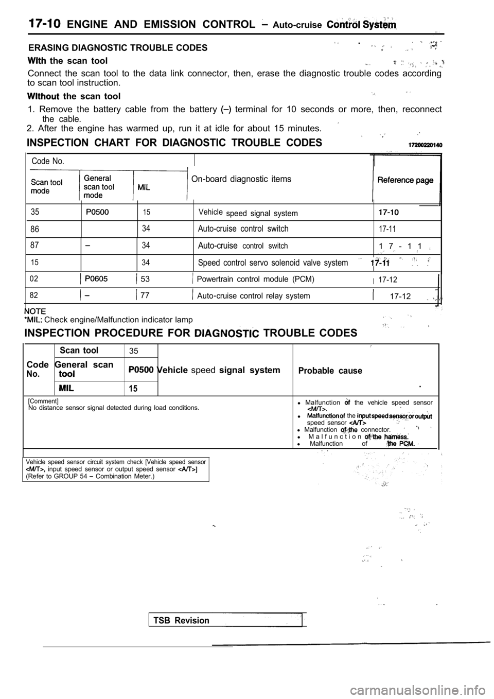
INSPECTION CHART FOR DIAGNOSTIC TROUBLE CODES
Code No.
On-board diagnostic items
35
86
15
34
Vehiclespeed signal system
Auto-cruise control switch17-11
87
15
34
34
Auto-cruisecontrol switch1 7 - 1 1
Speed control servo solenoid valve system
02 53 Powertrain control module (PCM)I17-12
82
77Auto cruise control relay system 17-12
Check engine/Malfunction indicator lamp
INSPECTION PROCEDURE FOR TROUBLE CODES
Scan tool35
Code General scan
No. Vehicle speedsignal systemProbable cause
15.
[Comment]No distance sensor signal detected during load cond itions.l
Malfunction the vehicle speed sensor
l the speed sensor l Malfunction connector.l M a l f u n c t i o nl Malfunction of . .
Vehicle speed sensor circuit system check [Vehicle speed sensor input speed sensor or output speed sensor (Refer to GROUP 54 Combination Meter.)
TSB Revision
Page 751 of 2103
![MITSUBISHI SPYDER 1990 Service Repair Manual ENGINE AND EMISSION CONTROL Auto-Cruise
Scan tool 86I
C o d e G e n e r a l s c a n
No. control switchP r o b a b l e c a u s e .
[Comment]Speed control switch input above maxi MITSUBISHI SPYDER 1990 Service Repair Manual ENGINE AND EMISSION CONTROL Auto-Cruise
Scan tool 86I
C o d e G e n e r a l s c a n
No. control switchP r o b a b l e c a u s e .
[Comment]Speed control switch input above maxi](/manual-img/19/57345/w960_57345-750.png)
ENGINE AND EMISSION CONTROL Auto-Cruise
Scan tool 86I
C o d e G e n e r a l s c a n
No. control switchP r o b a b l e c a u s e .
[Comment]Speed control switch input above maximum acceptable voltage.lMalfunction of the auto-cruise ,
Replace the auto-cruise control switch.
Scan tool
C o d e G e n e r a l s c a n
No.
34
control switchProbable
.
[Comment]lMalfunction of the auto-cruise control Speed control switch input below minimum acceptable
voltage.
Replace the auto-cruise control switch.
Scan tool15
C o d e G e n e r a l s c a n Speed control servo solenoid
No.system
I, .I
[Comment]l Malfunction of the speed control An open or shorted condition is detected in either the speed control vacuum or vent solenoidl
Malfunction of the connector.
control circuits. l
Malfunction of the
l Malfunction of ‘the PCM.
(Refer to
Measure at PCM connector l Disconnect the connector and
measure at the harness side.
l Voltage between terminal (78) and
groundl Voltage between terminal andgroundOK: positive voltage
and 107
NG
Repair
Check trouble
7 c o n n e c t o r :Check trouble symptom.
Repair
7Replace the PCM.
TSB Revision
Page 754 of 2103
![MITSUBISHI SPYDER 1990 Service Repair Manual ENGINE AND EMISSION CONTROL Auto-cruise Control System
INSPECTION PROCEDURE 3
When brake pedal is depressed,, auto-cruise control does not
cancel.
[Comment]A malfunction of the stop li MITSUBISHI SPYDER 1990 Service Repair Manual ENGINE AND EMISSION CONTROL Auto-cruise Control System
INSPECTION PROCEDURE 3
When brake pedal is depressed,, auto-cruise control does not
cancel.
[Comment]A malfunction of the stop li](/manual-img/19/57345/w960_57345-753.png)
ENGINE AND EMISSION CONTROL Auto-cruise Control System
INSPECTION PROCEDURE 3
When brake pedal is depressed,, auto-cruise control does not
cancel.
[Comment]A malfunction of the stop light switch or stop ligh t circuit may exist.
Probable cause
l Malfunction of the stop light switch.
l Malfunction of the connector.
l Malfunction of the
l Malfunction of the PCM.
Stop light switch check.
(Refer to
OK
Measure at stop
switch connector
lDisconnect the connector and mea-sure at the harness side.
l Voltage between terminal (1) and
ground positive voltage
following connectors:
NG
63 and
NG
Check troubleNGsymp Check the l i g h t a n d P C M . R e p a i r ,
OK Check trouble symptom.
Replace the PCM.
light switch and the
ground.
,
INSPECTION PROCEDURE 4
When selector lever is set to range, auto-cruise control does
not cancel.
[Comment]An open-circuit in the output signal circuit in IN range may be present.
OK
and.
TSB Revision
Inspect thebetween the NG
transaxle range switch and PCM.
OK
the PCM.
INSPECTION PROCEDURE 5
When auto-cruise control CANCEL switch is set to ON ,
auto-cruise control does not cancel. Probable cause
[Comment]An open-circuit inside the CANCEL switch may be pre
sent.l
Malfunction of the auto-cruise control switch.
Replace the auto-cruise control
Page 755 of 2103
![MITSUBISHI SPYDER 1990 Service Repair Manual ENGINE AND EMISSION CONTROL Auto-cruise System
INSPECTION PROCEDURE 6
Auto-cruise control cannot be set.
[Comment]A malfunction of the auto-cruise control switch circuit may exist. MITSUBISHI SPYDER 1990 Service Repair Manual ENGINE AND EMISSION CONTROL Auto-cruise System
INSPECTION PROCEDURE 6
Auto-cruise control cannot be set.
[Comment]A malfunction of the auto-cruise control switch circuit may exist.](/manual-img/19/57345/w960_57345-754.png)
ENGINE AND EMISSION CONTROL Auto-cruise System
INSPECTION PROCEDURE 6
Auto-cruise control cannot be set.
[Comment]A malfunction of the auto-cruise control switch circuit may exist.
c a u s e,lMalfunction of the auto-cruise control switch
l M a l f u n c t i o n o f spring.
l Malfunction of the connector.
l
of
Auto-cruise control switch checkN G
Measure at clock spring connector
Disconnect the connector and mea-
* Voltage between terminal (3) and
and 40 Check trouble symptom.
Check the harness between the clockspring and ground. Repair, if necessary.
INSPECTION PROCEDURE 7
Hunting (repeated acceleration and deceleration) oc curs at the
set vehicle speed.
[Comment]
A malfunction of a speed sensor, the speed control servo, or the vacuum supply may be present.
For vehicle speed sensor checkFor input speed sensor or output speed sensor check(Refer to GROUP 54 Combination Meter.)
Speed control servo checkN G
Probable cause
lMalfunction the vehicle speed sensor lMalfunction of the input speed or outputspeed sensor l Malfunction of the l Malfunction of the vacuum supply.
l Malfunction of the PCM.
OK
Vacuum supply check (ReferNG
the PCM.
INSPECTION PROCEDURE 8
When the auto-cruise control main switch is ON, the switch
indicator on the instrument panel does not illumina te.
(However, auto-cruise control is normal.) Probable cause
[Comment]l
Malfunction of the auto-cruise control main
Blown bulb in auto-cruise control main switch.switch.
theau t o - c r u i s e c o n t r o l m a i n s w i t c h .
TSB Revision
Page 756 of 2103

17-16ENGINE AND EMISSION CONTROL Auto-cruise Control System
INSPECTION PROCEDURE 9
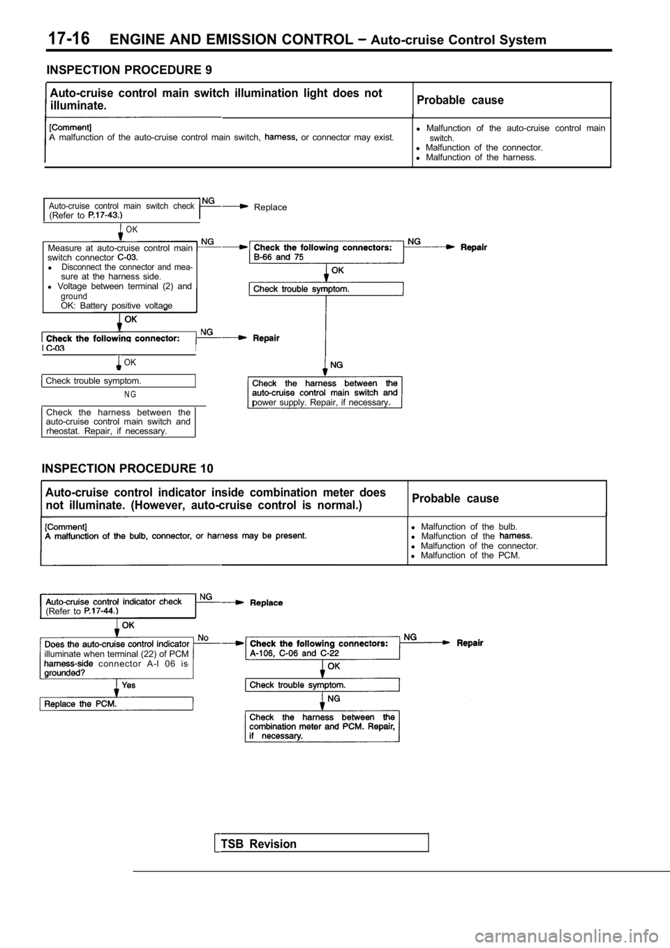
Auto-cruise control main switch illumination light does not
illuminate. Probable cause
A malfunction of the auto-cruise control main switc
h, or connector may exist.l
Malfunction of the auto-cruise control mainswitch.l Malfunction of the connector.
l Malfunction of the harness.
Auto-cruise control main switch check(Refer to Replace
OK
Measure at auto-cruise control main
switch connector
lDisconnect the connector and mea-sure at the harness side.
l Voltage between terminal (2) and
groundOK: Battery positive voltage
II
OK
Check trouble symptom.
N Gpower supply. Repair, if necessary.
Check the harness between the
auto-cruise control main switch and
rheostat. Repair, if necessary.
INSPECTION PROCEDURE 10
Auto-cruise control indicator inside combination me ter does
not illuminate. (However, auto-cruise control is no rmal.)Probable cause
TSB Revision
l
Malfunction of the bulb.
l Malfunction of the
l Malfunction of the connector.
l Malfunction of the PCM.
(Refer to
illuminate when terminal (22) of PCM connector A-l 06 is
Page 757 of 2103

ENGINE AND EMISSION CONTROL Auto-cruise System
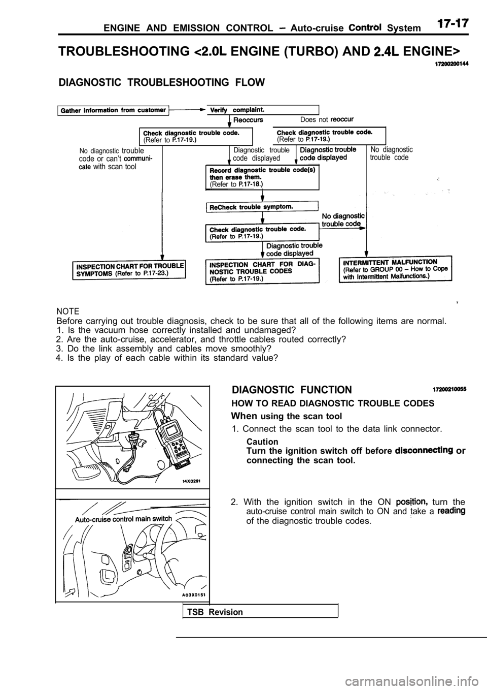
TROUBLESHOOTING ENGINE (TURBO) AND ENGINE>
DIAGNOSTIC TROUBLESHOOTING FLOW
Does not
(Refer to (Refer to
No diagnostic troubleDiagnostic troubleNo diagnostic
code or can’t code displayedtrouble code
with scan tool
(Refer to
NOTE
Before carrying out trouble diagnosis, check to be
sure that all of the following items are normal.
1. Is the vacuum hose correctly installed and undam aged?
2. Are the auto-cruise, accelerator, and throttle c ables routed correctly?
3. Do the link assembly and cables move smoothly?
4. Is the play of each cable within its standard va lue?
DIAGNOSTIC FUNCTION
HOW TO READ DIAGNOSTIC TROUBLE CODES
When using the scan tool
1. Connect the scan tool to the data link connector .
Caution
Turn the ignition switch off before or
connecting the scan tool.
2. With the ignition switch in the ON
turn the
auto-cruise control main switch to ON and take a
of the diagnostic trouble codes.
TSB Revision
Page 761 of 2103
![MITSUBISHI SPYDER 1990 Service Repair Manual ENGINE AND EMISSION CONTROL Auto-cruise Control’
Code 2 Vehicle speed signal system
[Comment]l Malfunction of the vehicle This diagnostic trouble code is output if the vehic le speed signa MITSUBISHI SPYDER 1990 Service Repair Manual ENGINE AND EMISSION CONTROL Auto-cruise Control’
Code 2 Vehicle speed signal system
[Comment]l Malfunction of the vehicle This diagnostic trouble code is output if the vehic le speed signa](/manual-img/19/57345/w960_57345-760.png)
ENGINE AND EMISSION CONTROL Auto-cruise Control’
Code 2 Vehicle speed signal system
[Comment]l Malfunction of the vehicle This diagnostic trouble code is output if the vehic le speed signals from the vehicle speed sensor l of connectorare not input to the auto-cruise control-ECU when t he vehicle speed is 40 km/h (25 mph) l
Malfunction of the harness
or more. l Malfunction of the auto-cruise
Check the vehicle speed sen(Refer to GROUP 54 CombinationMeter.)
1. NG
Measure at the vehicle speed sensor connector Check the following connector. l Disconnect the connector, and measure at the
harness side.O K
1. Voltage between 1 and ground (Ignition switch: ON)
NG
System voltage
2.Voltage between 3 and ground2. N G(Ignition switch: ON)
OK: 4.6 5.2 3.Continuity between 2 and ground3. N G
OK: Continuity
OK
Check trouble symptom.
N G
Check the harness between the speed sensor
Check the following
OKNG
Check trouble symptom.
NG
Check the harness between the auto-cruise ECU and the vehicle soeed sensor connector.
OKNG
Replace the auto-cruise control-ECU.
and ignition switch connector
OK
Check the ignition switch.
(Refer to GROUP 54 , ,
Check the harness between the vehicle speed sensorand the ground. Repair, if necessary.
Code Autocruise vacuum pump power supply systemProbable cause
[Comment]
This code will be output when the drive signals for the auto-cruise vacuum pump release valve,
control valve and motor are not input to the auto-c ruise control-ECU.l
the stop light l
Malfunction of the connector
l
l of the auto-cruise
at the auto-cruise vacuum
l Disconnect the connector and
l Voltage between terminal (1) and
OKN G Check the harness between the cruise vacuum pump and the cruise control-ECU.
and
Replace the auto-cruise control-ECU.
TSB Revision