Page 796 of 2103
ENGINE AND
Emission Control System
Vacuum
Engine speed
TSB Revision
4I
1.Disconnect the vacuum hose from the throttle body EGR
vacuum nipple. Connect a hand vacuum pump to the
nipple.
2.Start the engine and gradually raise the speed. The vacu-
um reading on the pump should remain constant.
ELECTRIC EGR TRANSDUCER SOLENOID
CHECK
NOTE
When disconnecting the vacuum hose, place an, ident ification
mark on it for proper re-connection.
1.Disconnect the vacuum hose from the electric EGR trans-
ducer.
2. Disconnect the harness connector.
3. Plug nipple (A).
4. Connect the hand vacuum pump to nipple (B).
5. Connect a positive pressure-type hand pump to ni pple
6. Use a jumper wire to connect the solenoid terminal to
the battery terminal.
7.Turn on and off the negative battery terminal side jumper
wire and applyvacuum and positive pressure to
the air tightness.
JumperwirePositive pressure
status
IVacuum statusI
Page 798 of 2103
ENGINE AND EMISSION CONTROL
INSPECTION
Check for damage, cracking or deterioration. Replace if faulty.
Caution
1. Stop the engine immediately if engine misfiring
occurs, otherwise an abnormally hot exhaust system
will damage the catalytic converter or other underb ody
parts.
2.
Correct and repair the ignition or fuel system if t here
are malfunctions, otherwise engine misfiring may
occur which will damage the catalytic converter.
3. Observe manufacturer’s specifications when doing
service work.
TSB Revision
Page 799 of 2103

(Turbo) 2.41 Engines
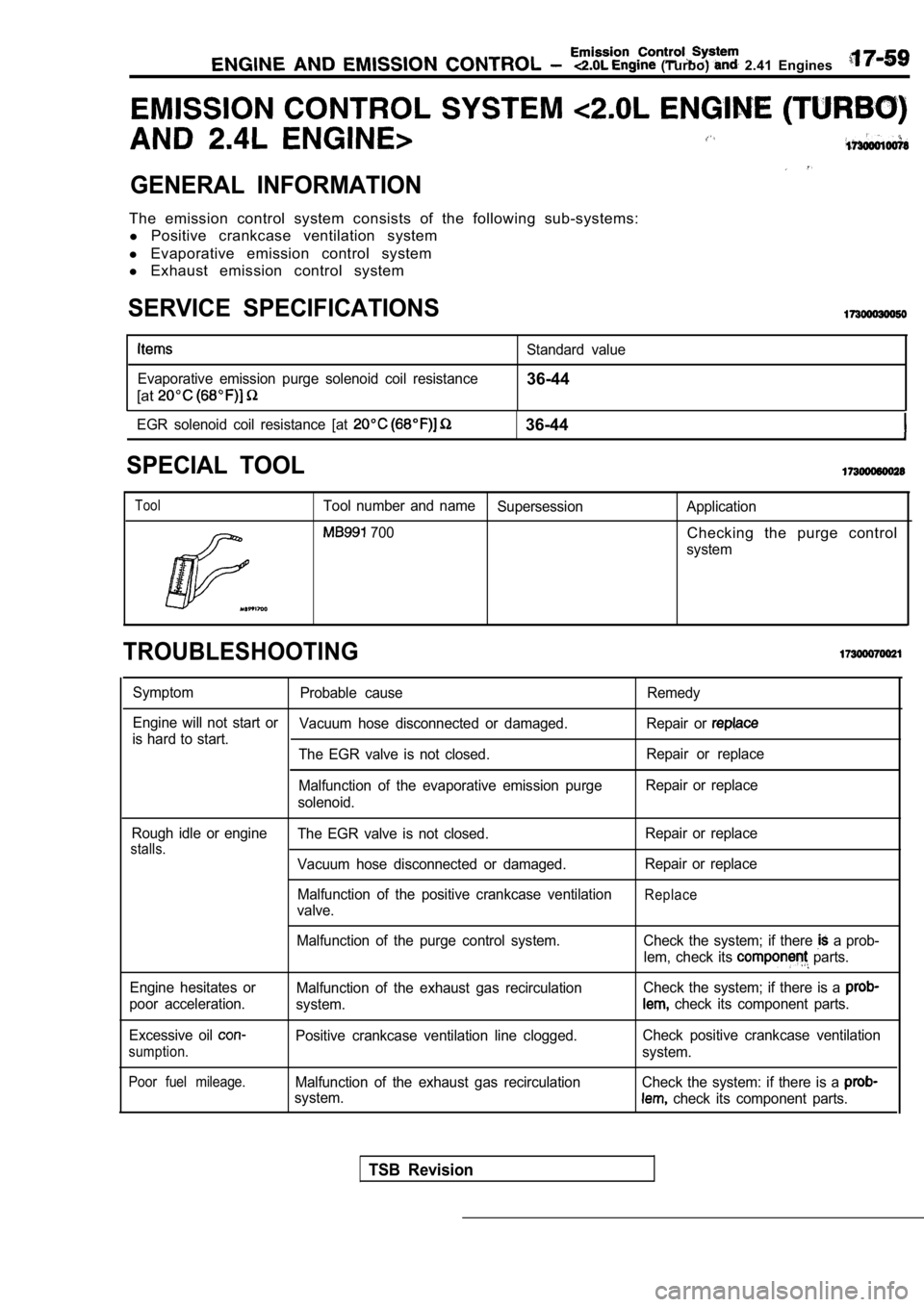
GENERAL INFORMATION
The emission control system consists of the following sub-systems:
l Positive crankcase ventilation system
l Evaporative emission control system
l Exhaust emission control system
SERVICE SPECIFICATIONS
Evaporative emission purge solenoid coil resistance
[at
Standard value
36-44
EGR solenoid coil resistance [at 36-44
SPECIAL TOOL
ToolTool number and name
Supersession Application
700Checking the purge control
system
TROUBLESHOOTING
SymptomProbable cause Remedy
Engine will not start or Vacuum hose disconnected or damaged. Repair or
is hard to start.
The EGR valve is not closed. Repair or replace
Malfunction of the evaporative emission purge Repair or replace
solenoid.
Rough idle or engine
stalls.The EGR valve is not closed.
Vacuum hose disconnected or damaged.
Malfunction of the positive crankcase ventilation
valve. Repair or replace
Repair or replace
Replace
Malfunction of the purge control system.
Engine hesitates or
poor acceleration.
Excessive oil
sumption.
Poor fuel mileage.
Malfunction of the exhaust gas recirculation
system.
Positive crankcase ventilation line clogged.
Malfunction of the exhaust gas recirculation
system. Check the system; if there
a prob-
lem, check its
parts.
Check the system; if there is a
check its component parts.
Check positive crankcase ventilation
system.
Check the system: if there is a
check its component parts.
TSB Revision
Page 802 of 2103
Engine and
VACUUM CIRCUIT DIAGRAM
Engine (Turbo)>intake air
Throttle bodyL: Light Blue
Red
B: Black
G: Green YellowW: WhiteTo combustion
chamber
Check
EVAP(ON: open)
EVAP canister
TSB Revision
Air
Turbocharger wastegateTurbochargerwasteate solenoid
ON: open)
Page 803 of 2103
Engine
Engine>
intake air
To combustion
chamber
G: Green
Yellow
White
Throttle body
Fuel pressure
regulator
Redpaintmark
EVAP purge
(ON: open)
EVAP canister
EGR(ON: closed)
EGR
VACUUM HOSE CHECK
Using the VACUUM HOSE ROUTING as a guide, check tha t
the vacuum hoses are correctly connected, and that there
are no bends or damage to the hoses.
VACUUM HOSE INSTALLATION
1.When connecting the vacuum hoses, they be securely
inserted onto the nipples.
2.To connect the hoses correctly, use the VACUUM HOSE ROUT-
ING as a guide.
TSB Revision
Page 806 of 2103
1 7 - 6 6 AND (Turbo) and
Engine (Turbo)>CRANKCASE VENTILATION SYSTEM CHECK
1.
2.
3.
4.
5.
17900110198
Remove the positive crankcase ventilation (PCV) val ve
from the rocker cover, then reconnect the PCV valve
to the vacuum supply hose (ventilation hose).
With the engine idling, put finger on the open end of
the PCV valve, and check for negative pressure (vacuum)
with finger.
NOTE
At this time, the plunger in the PCV valve should m ove
back and forth as the open end is covered and uncov ered.
If negative pressure is not felt, clean or replace the PCV
valve. Inspect the vacuum supply hose and vacuum su pply
hose port for restriction or plugged condition.
Install the PCV valve.
Tighten it to the specified torque. ‘Engine (Turbo)>
Specified torque: Nm (7.2
Revision
Page 807 of 2103
(Turbo) and
Engine (Turbo)>
Thin stick(Extremely light)
Vacuum side
Thin stick
PCV valve
POSITIVE VENTILATION VALVE”
CHECK
Hold the PCV valve with the vacuum side
Using light pressure depress the PCV valve spring
the thin stick mm. Release pressure on stick
to see if the PCV valve spring will lift
stick to its
original position.
2.If the stick returns quickly to its original positi on,
valve is OK. If the stick does not return quickly, Clean
or replace the PCV valve.
TSB Revision
Page 808 of 2103
17-68ENGINEAND EMISSION CONTROL (Turbo) and
EVAPORATIVE EMISSION CONTROL, SYSTEM
GENERAL INFORMATION Engine (Turbo)>
The evaporative emission control system preventsWhen driving with a low to medium load on the
fuel vapors generated in the fuel tank from escapin gengine, the fuel vapor absorbed by the EVAP
into the atmosphere.ter is drawn into the port of the throttle body.
Fuel vapors from the fuel tank flow through the When driving with a high load on the engine, the
fuel tank pressure control valve and vapor pipe/hos
epurge control valve opens and the fuel vapor
to be stored temporarily in the canister.sorbed by the EVAP canister is drawn into the air
intake hose.
SYSTEM DIAGRAM
Check valve EVAP canister
To air
hoseintake
EVAP purge s o l e n o i d
Revision
Engine control
module
I1
Barometric pressure sensor
Intake air temperature sensor
Engine coolant temperature sensor
Volume air flow sensor
COMPONENT LOCATION
Evaporative emission purge solenoid