1990 MITSUBISHI SPYDER check engine
[x] Cancel search: check enginePage 882 of 2103
MANUAL
ENGINE (NON-TURBO)>
Service Specifications/Lubricants/
Special Tools/Troubleshooting/On-vehicle Service
SERVICE SPECIFICATIONS22100020010
ItemsStandard value
Installation dimension of front roll stopper bracke t 43 3 (1.69
LUBRICANTS22110020025
ItemsSpecified lubricantQuantity (qts.)
Transaxle oil TEXACO MTX FLUID FM
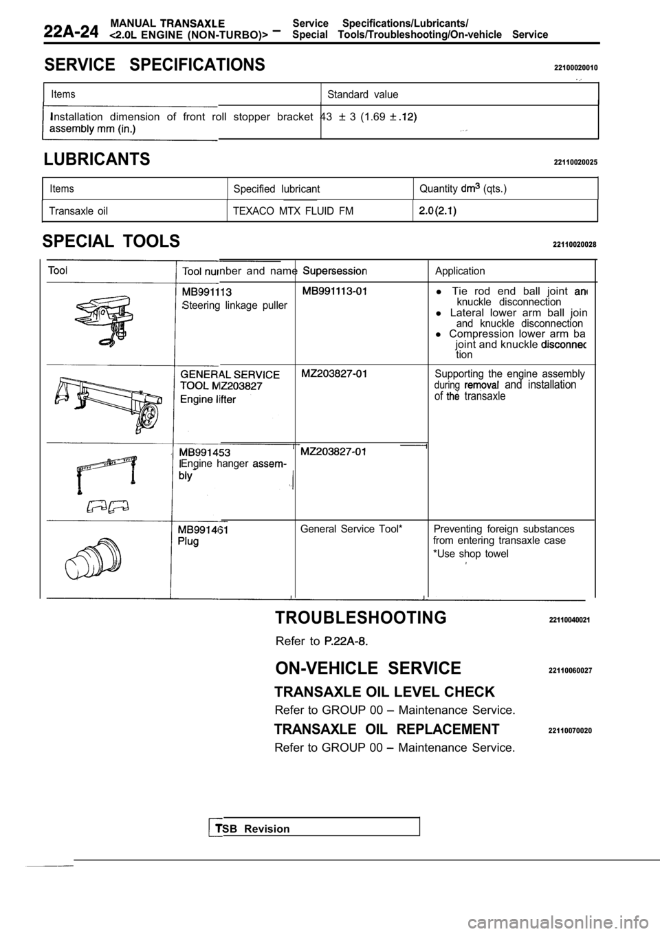
SPECIAL TOOLS22110020028
nber and name
Steering linkage puller
Application
l Tie rod end ball joint knuckle disconnectionl Lateral lower arm ball joinand knuckle disconnectionl Compression lower arm ba
joint and knuckle
tion
Supporting the engine assembly
during and installation
of transaxle
Engine hanger
General Service Tool* Preventing foreign substances from entering transaxle case
*Use shop towel
TSB Revision
TROUBLESHOOTING
Refer to
ON-VEHICLE SERVICE
TRANSAXLE OIL LEVEL CHECK
Refer to GROUP 00
Maintenance Service.
TRANSAXLE OIL REPLACEMENT
Refer to GROUP 00 Maintenance Service.
22110040021
22110060027
22110070020
Page 886 of 2103
MANUAL TRANSAXLE
ENGINE (NON-TURBO)> Transaxle Control
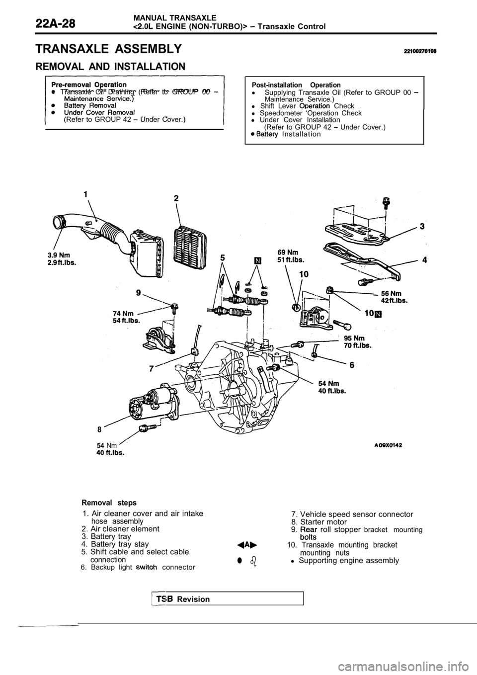
TRANSAXLE ASSEMBLY
REMOVAL AND INSTALLATION
l Transaxle Oil Draining (Refer to GROUP 00
(Refer to GROUP 42 Under Cover.)
Post-installation Operationl
Supplying Transaxle Oil (Refer to GROUP 00 Maintenance Service.)l Shift Lever Check
l Speedometer ‘Operation Check
l Under Cover Installation
(Refer to GROUP 42
Under Cover.) I n s t a l l a t i o n
8
54Nm
Removal steps
1. Air cleaner cover and air intakehose assembly2. Air cleaner element
3. Battery tray
4. Battery tray stay
5. Shift cable and select cable
connection6. Backup light connectorl b
7. Vehicle speed sensor connector
8. Starter motor
9.
roll stopper bracket mounting
10. Transaxle mounting bracket
mounting nuts
l Supporting engine assembly
Revision
Page 1005 of 2103
Differential Bearing
MANUAL TRANSAXLE Preload Adjustment
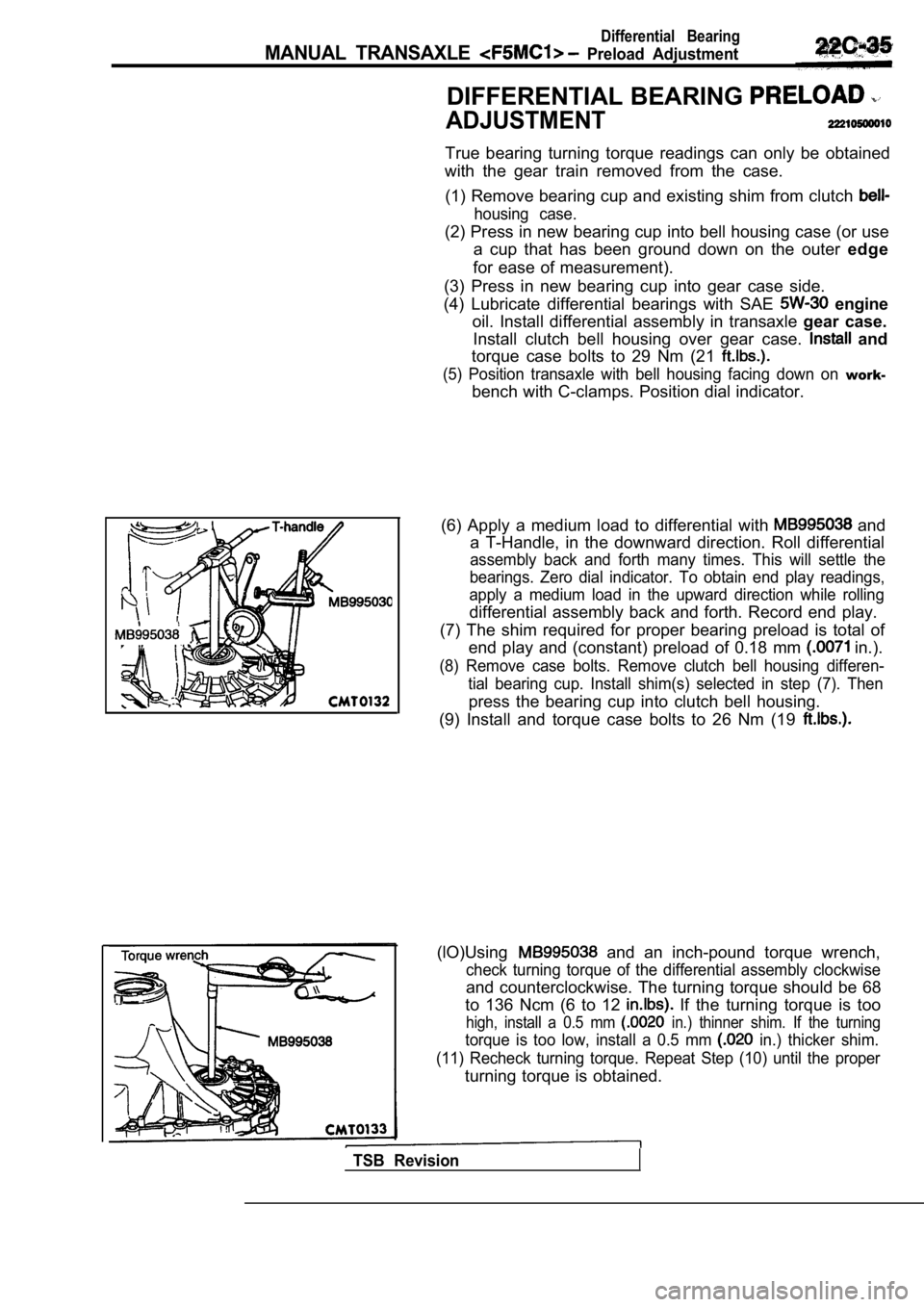
DIFFERENTIAL BEARING
ADJUSTMENT
True bearing turning torque readings can only be obtained
with the gear train removed from the case.
(1) Remove bearing cup and existing shim from clutc h
housing case.
(2) Press in new bearing cup into bell housing case (or use
a cup that has been ground down on the outer edge
for ease of measurement).
(3) Press in new bearing cup into gear case side.
(4) Lubricate differential bearings with SAE
engine
oil. Install differential assembly in transaxle gear case.
Install clutch bell housing over gear case.
and
torque case bolts to 29 Nm (21
(5) Position transaxle with bell housing facing dow n on work-
bench with C-clamps. Position dial indicator.
(6) Apply a medium load to differential with
and
a T-Handle, in the downward direction. Roll differe ntial
assembly back and forth many times. This will settl e the
bearings. Zero dial indicator. To obtain end play r eadings,
apply a medium load in the upward direction while r olling
differential assembly back and forth. Record end play.
(7) The shim required for proper bearing preload is total of
end play and (constant) preload of 0.18 mm
in.).
(8) Remove case bolts. Remove clutch bell housing d ifferen-
tial bearing cup. Install shim(s) selected in step (7). Then
press the bearing cup into clutch bell housing.
(9) Install and torque case bolts to 26 Nm (19
(lO)Using and an inch-pound torque wrench,
check turning torque of the differential assembly c lockwise
and counterclockwise. The turning torque should be 68
to 136 Ncm (6 to 12
If the turning torque is too
high, install a 0.5 mm in.) thinner shim. If the turning
torque is too low, install a 0.5 mm in.) thicker shim.
(11) Recheck turning torque. Repeat Step (10) until the proper
turning torque is obtained.
TSB Revision
Page 1009 of 2103
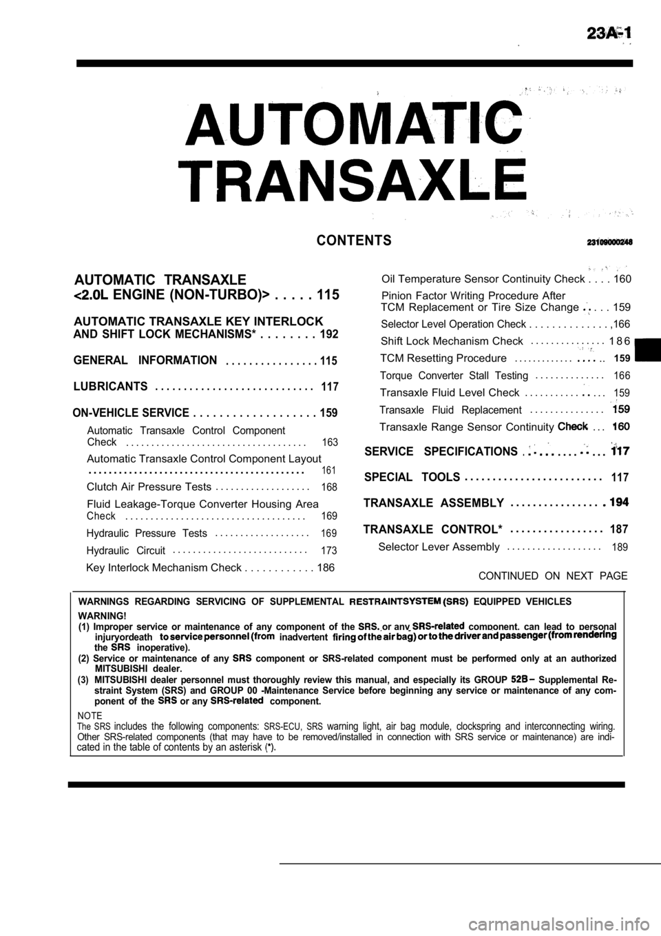
CONTENTS
AUTOMATIC TRANSAXLE
ENGINE (NON-TURBO)> . . . . . 115
AUTOMATIC TRANSAXLE KEY INTERLOCK
AND SHIFT LOCK MECHANISMS* . . . . . . . . 192
GENERAL INFORMATION
. . . . . . . . . . . . . . . . 115
LUBRICANTS. . . . . . . . . . . . . . . . . . . . . . . . . . . .117
ON-VEHICLE SERVICE . . . . . . . . . . . . . . . . . . . 159
Automatic Transaxle Control Component
Oil Temperature Sensor Continuity Check . . . . 160
Pinion Factor Writing Procedure After
TCM Replacement or Tire Size Change
. . . 159
Selector Level Operation Check . . . . . . . . . . . . . . ,166
Shift Lock Mechanism Check. . . . . . . . . . . . . . .
1 8 6
TCM Resetting Procedure . . . . . . . . . . . . .
..159
Torque Converter Stall Testing. . . . . . . . . . . . . .166
Transaxle Fluid Level Check . . . . . . . . . . .. . .159
Transaxle Fluid Replacement. . . . . . . . . . . . . . .
Transaxle Range Sensor Continuity . . .
Check. . . . . . . . . . . . . . . . . . . . . . . . . . . . . . . . . . . .163SERVICE SPECIFICATIONS.. . . .. . .Automatic Transaxle Control Component Layout
. . . . . . . . . . . . . . . . . . . . . . . . . . . . . . . . . . . . . . . . . . .
161SPECIAL TOOLS. . . . . . . . . . . . . . . . . . . . . . . . .117Clutch Air Pressure Tests . . . . . . . . . . . . . . . . . . .168
Fluid Leakage-Torque Converter Housing Area
Check. . . . . . . . . . . . . . . . . . . . . . . . . . . . . . . . . . . .169
Hydraulic Pressure Tests. . . . . . . . . . . . . . . . . . .169
Hydraulic Circuit. . . . . . . . . . . . . . . . . . . . . . . . . . .173
TRANSAXLE ASSEMBLY. . . . . . . . . . . . . . . .
TRANSAXLE CONTROL*. . . . . . . . . . . . . . . . .187
Selector Lever Assembly. . . . . . . . . . . . . . . . . . .189
Key Interlock Mechanism Check . . . . . . . . . . .
. 186CONTINUED ON NEXT PAGE
WARNINGS REGARDING SERVICING OF SUPPLEMENTAL EQUIPPED VEHICLES
WARNING! (1) Improper service or maintenance of any componen t of the
or any component, can lead to personal
injuryordeath inadvertent the inoperative).
(2) Service or maintenance of any component or SRS-related component must be perform ed only at an authorized
MITSUBISHI dealer.
(3)MITSUBISHI dealer personnel must thoroughly review this manual, and especially its GROUP Supplemental Re-
straint System (SRS) and GROUP 00 -Maintenance Serv ice before beginning any service or maintenance of any com-
ponent of the
or any component.
NOTEThe SRS includes the following components: SRS-ECU, SRS warning light, air bag module, clockspring and inte rconnecting wiring.Other SRS-related components (that may have to be removed/installed in connection with SRS service or maintenance) are indi-cated in the table of contents by an asterisk
Page 1019 of 2103
AUTOMATIC TRANSAXLE
(TURBO) AND ENGINE> Troubleshooting
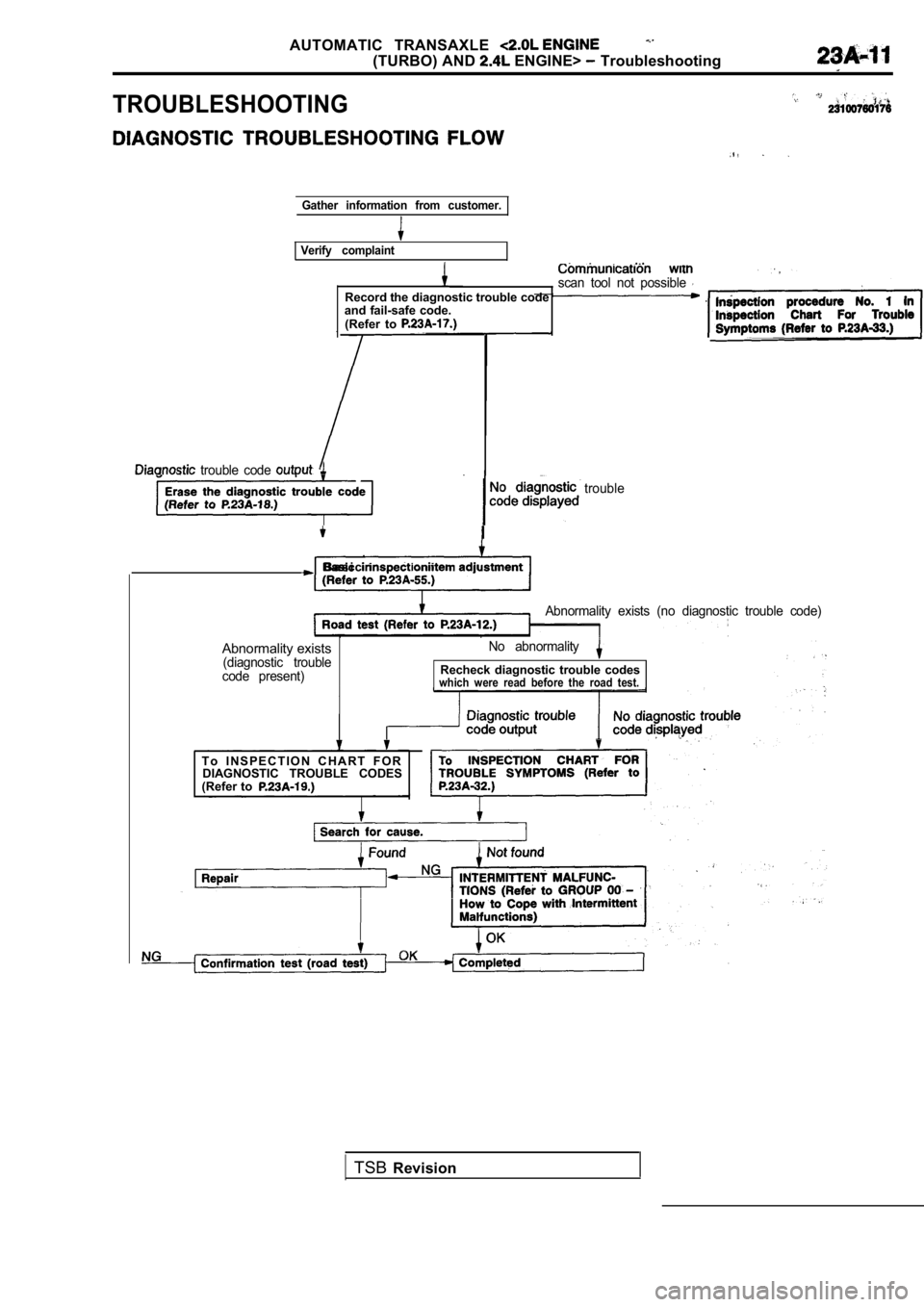
TROUBLESHOOTING
Gather information from customer.
Verify complaint
scan tool not possible Record the diagnostic trouble code and fail-safe code.(Refer to
trouble code
trouble
B a s i c
Abnormality exists (no diagnostic trouble code)
Abnormality exists(diagnostic trouble
code present) No abnormalityRecheck diagnostic trouble codeswhich were read before the road test.
T o I N S P E C T I O N C H A R T F O R
DIAGNOSTIC TROUBLE CODES
(Refer to
TSB Revision
Page 1026 of 2103
AUTOMATIC TRANSAXLE ENGINE
(TURBO) AND
Troubleshooting
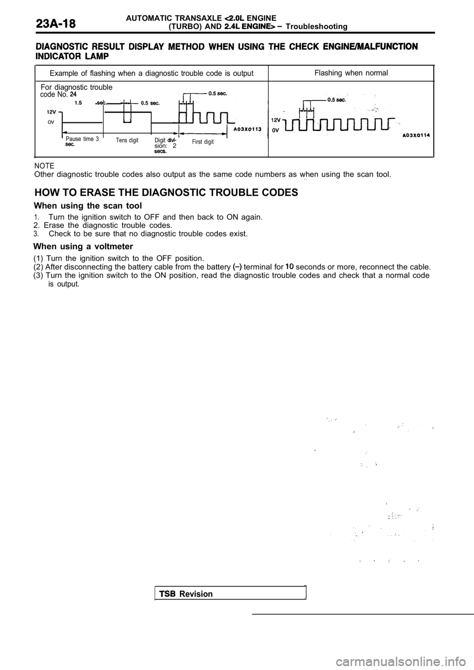
Example of flashing when a diagnostic trouble code is output
For diagnostic trouble
code No.
ov
Pause time 3Tens digitDigitsion: 2First digit
Flashing when normal
NOTE
Other diagnostic trouble codes also output as the s ame code numbers as when using the scan tool.
HOW TO ERASE THE DIAGNOSTIC TROUBLE CODES
When using the scan tool
1.Turn the ignition switch to OFF and then back to ON again.
2. Erase the diagnostic trouble codes.
3.Check to be sure that no diagnostic trouble codes e xist.
When using a voltmeter (1) Turn the ignition switch to the OFF position.
(2) After disconnecting the battery cable from the battery
terminal for seconds or more, reconnect the cable.
(3) Turn the ignition switch to the ON position, re ad the diagnostic trouble codes and check that a no rmal code
is output.
,
Revision
Page 1029 of 2103
![MITSUBISHI SPYDER 1990 Service Repair Manual AUTOMATIC TRANSAXLE ENGINE
(TURBO) AND ENGINE>
Code No. Throttle position sensor system Probable cause
[Comment] of the throttle If the TPS output becomes 4.6 or more at idle, T MITSUBISHI SPYDER 1990 Service Repair Manual AUTOMATIC TRANSAXLE ENGINE
(TURBO) AND ENGINE>
Code No. Throttle position sensor system Probable cause
[Comment] of the throttle If the TPS output becomes 4.6 or more at idle, T](/manual-img/19/57345/w960_57345-1028.png)
AUTOMATIC TRANSAXLE ENGINE
(TURBO) AND ENGINE>
Code No. Throttle position sensor system Probable cause
[Comment] of the throttle If the TPS output becomes 4.6 or more at idle, TPS output is excessive, and of connector
trouble code No. 11 is output. If the TPS output be comes 0.2 or less at times other than l of idling, TPS output is insufficient and diagnostic t rouble code No. 12 is output. If the TPS output
and the target value inside the TCM do not match ev en after compensation is carried out while
the engine is idling, the TPS sensor is defective and diagnostic trouble code No. 13 is output.
If the TPS voltage becomes 0.2 or less or 1.2 or more while the engine is idling, the
TPS adjustment is defective and diagnostic trouble code No. 14 is output.
Check the throttle position sensor
NG Replace
(Refer to GROUP On-vehicle
Inspection of Components.)
OK
Check the following connectors:
l
OK
NG Repair
Check trouble symptom.
NG
Replace the TCM.
Code No. 15, 16 Oil temperature sensor system
[Comment] If the oil temperature sensor output is 4.4 or higher (oil temperature does not increase) evenafter driving for 10 minutes or more, there is an o pen circuit in the oil temperature sensor
and diagnostic trouble code No. 15 is output.
When the oil temperature sensor output is 0.2 or less (for 1 second or more), it is judgedthat there is a short-circuit in the oil temperatur e sensor and diagnostic trouble code No. 16is output.
Probable cause
o f o i l
l T C M
Oil temperature sensor check.
(Refer to NG Replace
OK
Measure at the oil temperature sensorconnectorl Disconnect the connector, and
measure at theconnector side.
l Voltage between terminal (1) and
ground (Ignition switch: ON)
l
Continuity between terminal (2) and
ground
OK:Continuity
OK
Check the following connector: Repair
, I .
Check the harness wire between con-
nectors of oil temperature sensor and
Replace the
l Repair
OK
Check trouble symptom.Check the harness wire between con-
TSB Revision
Page 1030 of 2103
![MITSUBISHI SPYDER 1990 Service Repair Manual AUTOMATIC TRANSAXLE
(TURBO) AND ENGINE> Troubleshdoting
Code No.
servo switch c a u s e
[Comment]l Malfunction of servo If the servo switch does not ON in 1 and 3 range MITSUBISHI SPYDER 1990 Service Repair Manual AUTOMATIC TRANSAXLE
(TURBO) AND ENGINE> Troubleshdoting
Code No.
servo switch c a u s e
[Comment]l Malfunction of servo If the servo switch does not ON in 1 and 3 range](/manual-img/19/57345/w960_57345-1029.png)
AUTOMATIC TRANSAXLE
(TURBO) AND ENGINE> Troubleshdoting
Code No.
servo switch c a u s e
[Comment]l Malfunction of servo If the servo switch does not ON in 1 and 3 range within 5 seconds, there is l
Malfunction of connector
an open circuit in the servo switch and diagnostic trouble code No. 21 is output. l
Malfunction of TCM
If the servo switch does not OFF in 2 and 4 range, there is a circuit in
the servo switch and diagnostic trouble code No. 22 is output,
(Refer to
OK
N G Replace
Repair
lDisconnect the connector and I
sure at the harnessside. OK
servo switch and TCM
Check trouble Replace the TCM.
NG
Check the harness wire between the servo switch and TCM con-
nectors. if
TSB Revision
Code No. 23 Ignition signal Probable cause
[Comment]l Malfunction of ignition coil
If ignition pulses are not input to the TCM while t he engine is idling, there is an open circuit l
in the ignition signal line and diagnostic trouble code No. 23 is output.Malfunction of power transistor
l Malfunction of connector
l Malfunction of TCM
Is the engine speed displayed on the
tachometer correct?
Yes
lInspection procedures circuit system (Refer to GROUP
.
NG Repair
OK
Check trouble symptom.
NG
N G Repairpower transistor andTCMconnectors.
the TCM.