1990 MITSUBISHI SPYDER check engine
[x] Cancel search: check enginePage 574 of 2103
![MITSUBISHI SPYDER 1990 Service Repair Manual E N G I N E
A N D ,
Code No. Differential
Malfunction
[Comment]BackgroundManifold differential se.
l pressure in the intake manifold. o r l o o s e Engine control. lThe engine co MITSUBISHI SPYDER 1990 Service Repair Manual E N G I N E
A N D ,
Code No. Differential
Malfunction
[Comment]BackgroundManifold differential se.
l pressure in the intake manifold. o r l o o s e Engine control. lThe engine co](/manual-img/19/57345/w960_57345-573.png)
E N G I N E
A N D ,
Code No. Differential
Malfunction
[Comment]BackgroundManifold differential se.
l pressure in the intake manifold. o r l o o s e Engine control. lThe engine control module checks whether the voltage output by manifold differential sure sensor is within a specified range.
Check Area, Judgement Criteria.
1. Check Areal min or more have passed after the engine was start ed.[However, this is only when the engine coolant temperature is or lower
when the engine is started.]
Engine coolant temperature is not lower than Intake air temperature is not lower than Barometric pressure is 76 (11 psi.) or higher. Volumetric efficiency is 30% 55%.
Judgement Criteria . ,
Sensor output voltage has continued to be not lowe
r than [corresponding toan absolute pressure of 118 (17 psi) or higher] for 4 sec.orSensoroutput voltage has continued to be not higher than 0.1 [corresponding to ---
an absolute pressure of 2.4 (0.3 psi) or lower] for 4 sec.
2. Check Area
8 min or more have passed engine Started.
[However, this is only when the engine coolant or lower when the engine is Engine coolant temperature is not lower than Intake air temperature is not lower than Barometric pressure is 76 (11 psi.) or higher. Volumetric efficiency is 30% or lower.
Judgement Criteria ,
l Sensor output voltage is 4.2 or higher for 4 seconds [absolute pressure is 108 (16 psi.) or more]
Check Area 8 min or more have passed after the engine was sta rted.
,
.
. , ,
[However, this is only when the engine coolant temperature is or lowerwhen engine is started.]
l Engine coolant temperature is not lower than .l Intake air temperature is not lower than l Barometric pressure is 76 (11 psi.) or higher. Volumetric efficiency is 70% or higher.
Judgement Criterial Sensor output voltage is or lower for 4 seconds [absolute pressure is 46 (6.7 psi.) or less]I
TSB Revision.
Page 575 of 2103

ENGINE (TURBO),
AND ENGINE>
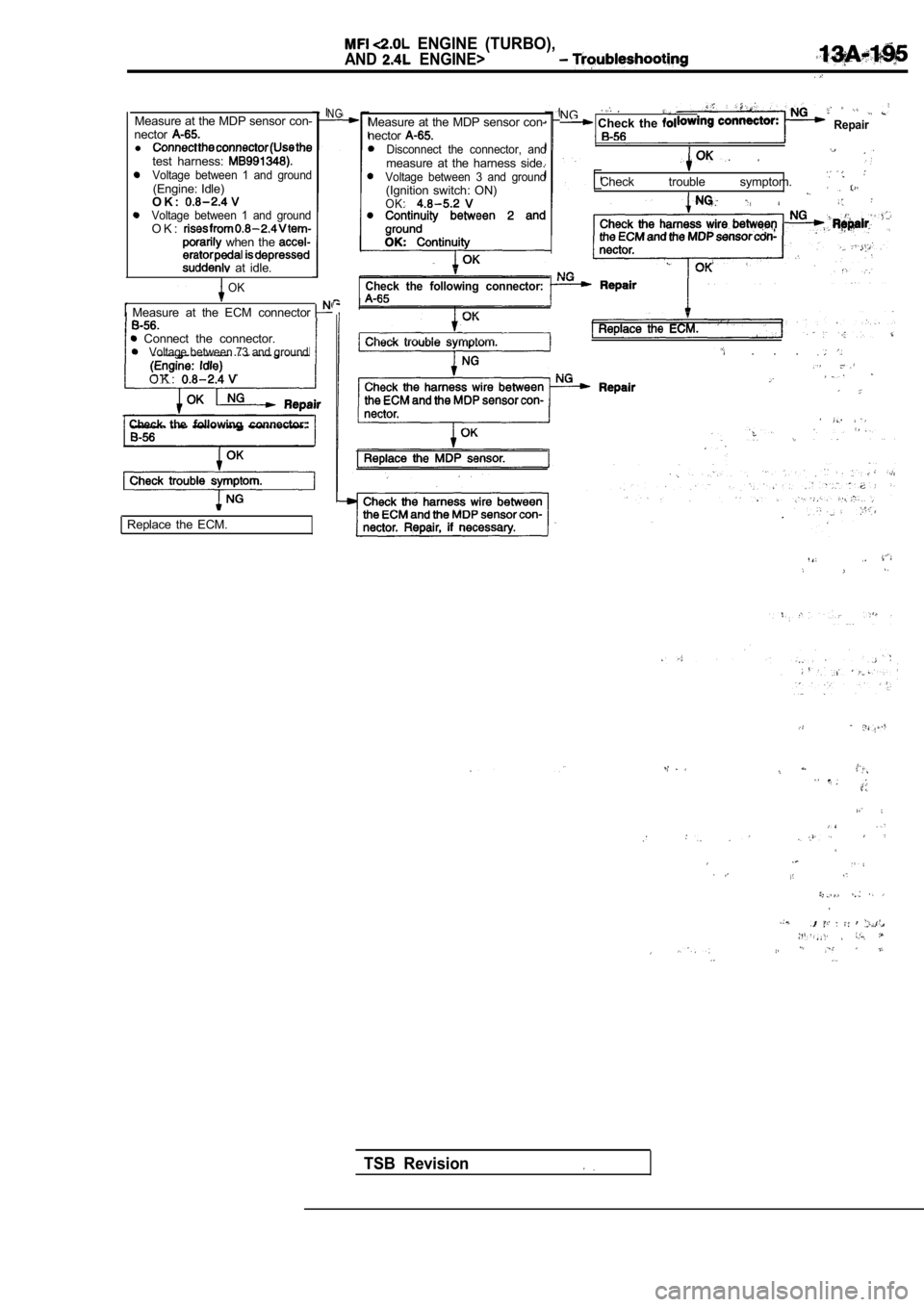
Measure at the MDP sensor con-
nector
l test harness: Voltage between 1 and ground(Engine: Idle)
O K :
Voltage between 1 and groundO K : when the
at idle.
NG
OK
Measure at the ECM connector
Connect the connector.Voltage between 73 and ground
O K :
Check the following connector:
Replace the ECM. Measure at the MDP sensor con-
nector
Disconnect the connector, andmeasure at the harness side.Voltage between 3 and ground(Ignition switch: ON)OK:
NG Check the Repair
Check trouble symptom.
Check the following connector:
. . .
TSB Revision
Page 576 of 2103
![MITSUBISHI SPYDER 1990 Service Repair Manual (TURBO)
AND ENGINE> Troubleshooting
Code No. Generator Terminal Circuit Malfunction
[Comment]
Background
lWhen the generator field coil is controlled, the generator terminal inpu MITSUBISHI SPYDER 1990 Service Repair Manual (TURBO)
AND ENGINE> Troubleshooting
Code No. Generator Terminal Circuit Malfunction
[Comment]
Background
lWhen the generator field coil is controlled, the generator terminal inpu](/manual-img/19/57345/w960_57345-575.png)
(TURBO)
AND ENGINE> Troubleshooting
Code No. Generator Terminal Circuit Malfunction
[Comment]
Background
lWhen the generator field coil is controlled, the generator terminal inputs a signal to
the engine control module.
lThe engine control module detects the generator out put with the input signal, and controlsthe idle air control motor according to the generator output.
Check Area
l Engine speed is higher than 50
Judgement CriterialInput voltage from the generator terminal has continued to be not lower than 4.5 for 20 sec.
Measure at the generator connector
l Connect the connector.
l Voltage between 4 and ground
Engine: Idle
Radiator fan: stopped
Headlight: off
on
Stop Lamp: off on
Rear defogger switch: off on
OK: voltage drops
NG
Measure at the generator connector lDisconnect the connector, and measure at the harnes s side.
l Voltage between 4 and ground (Ignition switch: ON)
O K :
Probable cause
lOpen circuit in generator terminal circuitl Enginecontrol module failed
,
Replace the ECM.
,
. ,
Check trouble symptom.
NG
NG
Repairbetween theECMand the
OK
connector:
NG Repair
OK
Check trouble symptom. generator
NG
Check the NG Repair Replace the ECM.I
TSB Revision
Replace the generator.1
Code No. Serial Communication Link Malfunction
Probable cause
(with
[Comment]l Automatic transaxle control system Backgroundl Open or short circuit in communication linelThe engine control module receives message signals from the transaxle control modulebetween engine module and transaxlevia the communication line. control module, or poor connector contactlThe engine control module monitors abnormalities in message signals resulting froml
Transaxle control module failed.
a broken communication line or transaxle control mo dule problems.l Engine control module failed.
Check Areal 2 seconds or more have passed since starting was co mpleted.
Judgement CriterialAbnormality in communication line (TCM to ECM) with transaxle control module l Problem with transaxle control module (TCM).
Page 577 of 2103

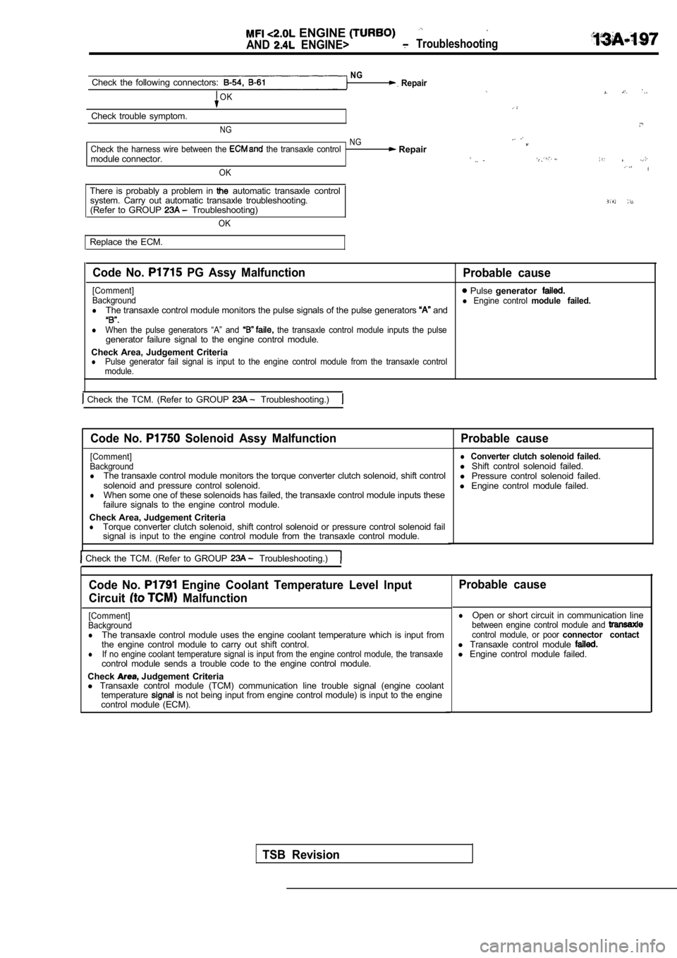
ENGINE
AND ENGINE> Troubleshooting
NGCheck the following connectors: Repair
OK
Check trouble symptom.
NG
NGCheck the harness wire between the the transaxle control Repairmodule connector. ,
OK
There is probably a problem in automatic transaxle control
system. Carry out automatic transaxle troubleshooti ng.
(Refer to GROUP Troubleshooting)
OK
Replace the ECM.
Code No. PG Assy Malfunction
Probable cause
[Comment] Pulse generatorBackgroundl Engine control module failed.lThe transaxle control module monitors the pulse sig nals of the pulse generators and
lWhen the pulse generators “A” and the transaxle control module inputs the pulsegenerator failure signal to the engine control modu le.
Check Area, Judgement Criteria
lPulse generator fail signal is input to the engine control module from the transaxle control
module.
Check the TCM. (Refer to GROUP Troubleshooting.)
Code No. Solenoid Assy Malfunction Probable cause
[Comment]
Background
lThe transaxle control module monitors the torque co nverter clutch solenoid, shift control
solenoid and pressure control solenoid.
lWhen some one of these solenoids has failed, the tr ansaxle control module inputs these
failure signals to the engine control module.
Check Area, Judgement Criteria
lTorque converter clutch solenoid, shift control sol enoid or pressure control solenoid fail
signal is input to the engine control module from t he transaxle control module.
Check the TCM. (Refer to GROUP Troubleshooting.)
l Converter clutch solenoid failed.l Shift control solenoid failed.
l Pressure control solenoid failed.
l Engine control module failed.
Code No. Engine Coolant Temperature Level Input
Circuit
Malfunction
[Comment]
Background
lThe transaxle control module uses the engine coolan t temperature which is input from
the engine control module to carry out shift contro l.
lIf no engine coolant temperature signal is input from the engine control module, the transaxlecontrol module sends a trouble code to the engine c ontrol module.
Check
Judgement Criteria
l Transaxle control module (TCM) communication line t rouble signal (engine coolant
temperature
is not being input from engine control module) is input to the engine
control module (ECM).
Probable cause
lOpen or short circuit in communication linebetween engine control module and control module, or poor connector contactl Transaxle control module l Engine control module failed.
TSB Revision
Page 578 of 2103

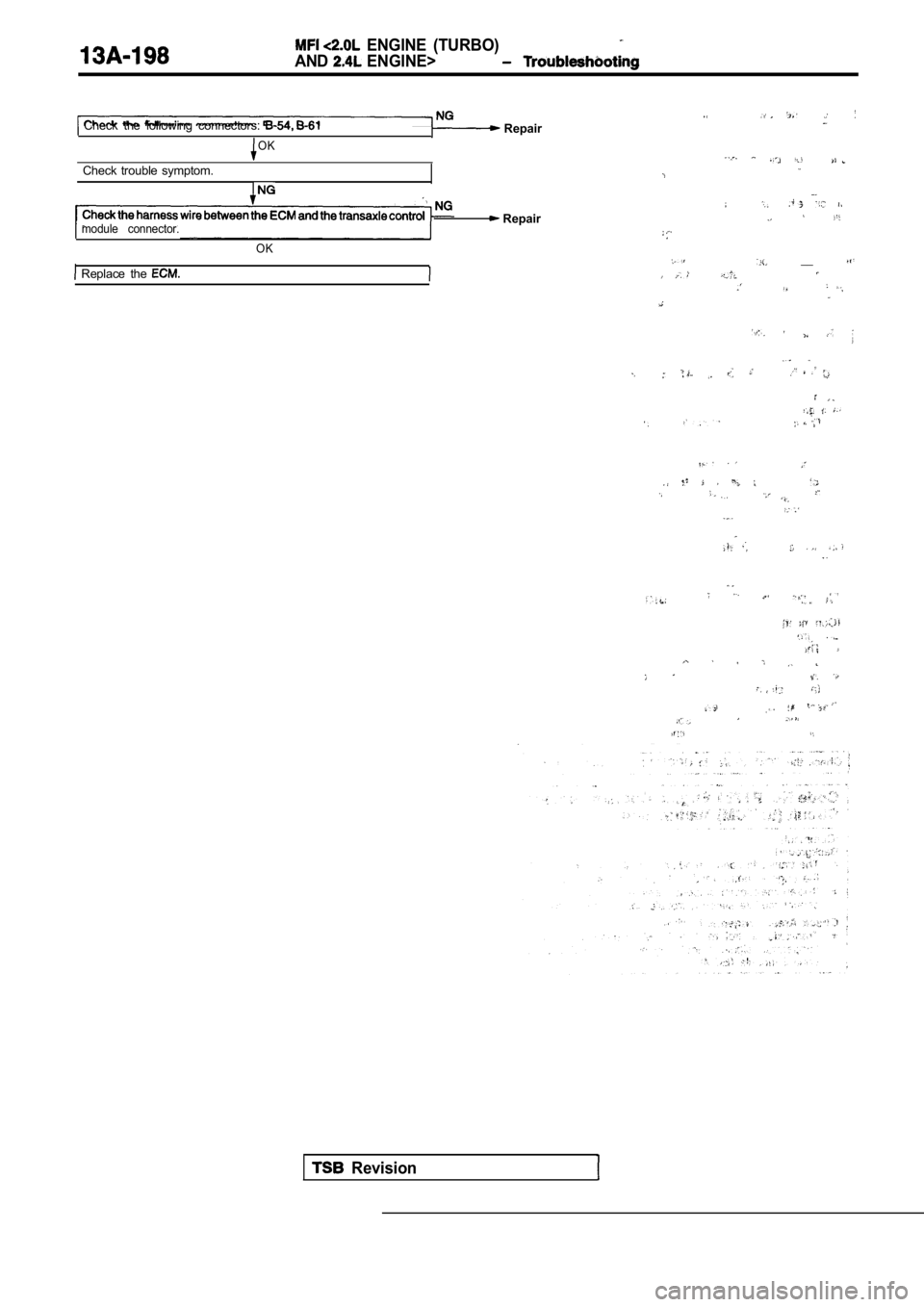
ENGINE (TURBO)
AND ENGINE>
Check the following connectors: Repair
OK
Check trouble symptom.
module connector.
Replace the
OK
Repair
__
Revision
Page 579 of 2103

E N G I N E ( T U R B O )
AND ENGINE>
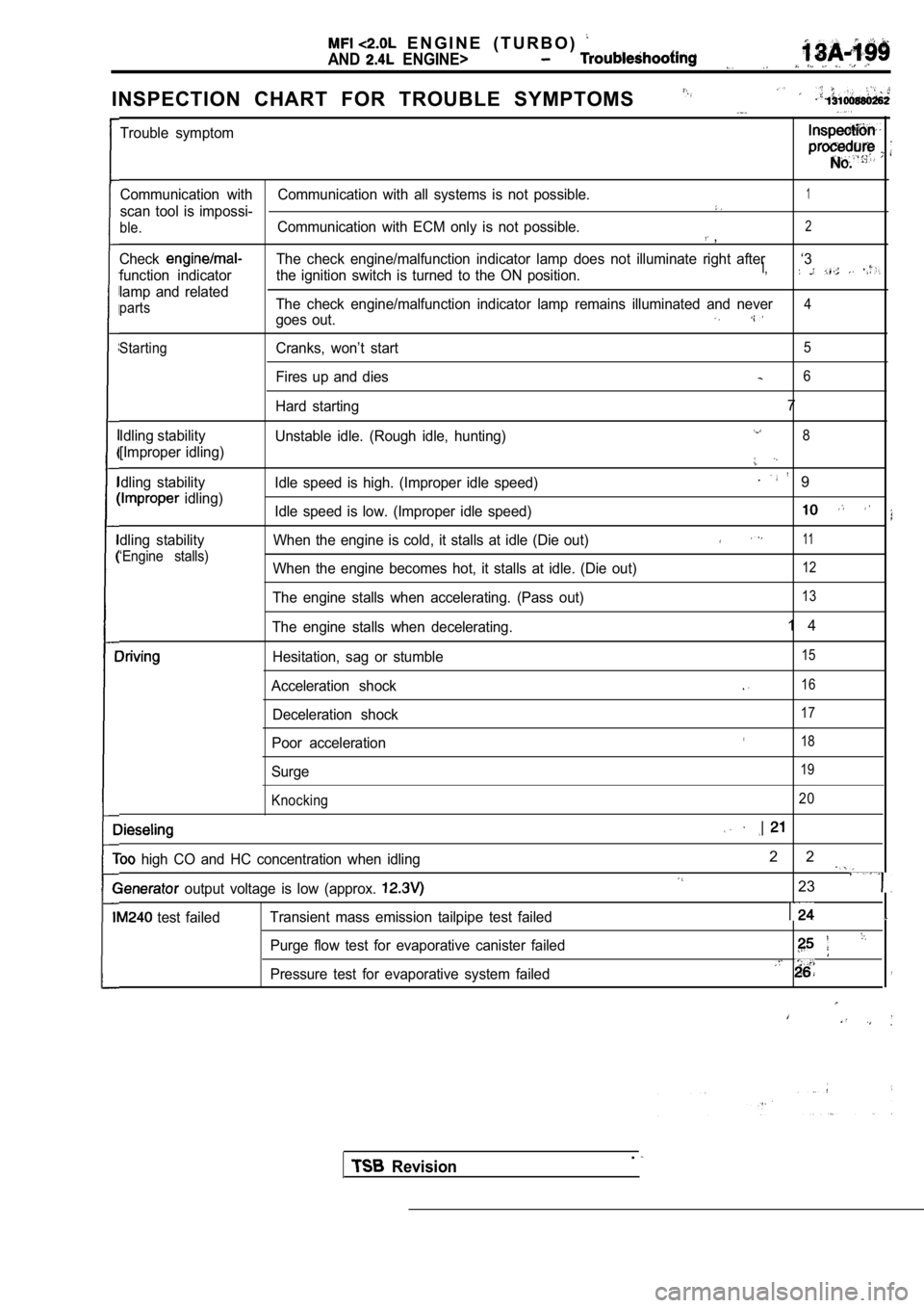
INSPECTION CHART FOR TROUBLE SYMPTOMS
Trouble symptom
Communication with Communication with all systems is not possible.1
scan tool is impossi-
ble.Communication with ECM only is not possible.2 ,
CheckThe check engine/malfunction indicator lamp does not illuminate right after ‘3
function indicator the ignition switch is turned to the ON position.I,
lamp and related
partsThe check engine/malfunction indicator lamp remains illuminated and never4
goes out.
StartingCranks, won’t start5
Fires up and dies6
Hard starting7
Idling stability
Unstable idle. (Rough idle, hunting)8
[Improper idling)
dling stabilityIdle speed is high. (Improper idle speed). 9
idling)
Idle speed is low. (Improper idle speed)
dling stability When the engine is cold, it stalls a t idle (Die out)11
‘Engine stalls)When the engine becomes hot, it stalls at idle. (Die out)12
The engine stalls when accelerating. (Pass out)13
The engine stalls when decelerating.1 4
Hesitation, sag or stumble15
Acceleration shock16
Deceleration shock17
Poor acceleration18
Surge19
Knocking 20
high CO and HC concentration when idling2 2
output voltage is low (approx. 23
test failed
Transient mass emission tailpipe test failed
Purge flow test for evaporative canister failed
Pressure test for evaporative system failed,
Revision.
Page 581 of 2103
![MITSUBISHI SPYDER 1990 Service Repair Manual ENGINE (TURBO)
AND ENGINE>
INSPECTION PROCEDURE 1
Communication with scan tool is not possible. ,
tion with all systems is not possible.)
[Comment] M a l f u n c t i o n c o n MITSUBISHI SPYDER 1990 Service Repair Manual ENGINE (TURBO)
AND ENGINE>
INSPECTION PROCEDURE 1
Communication with scan tool is not possible. ,
tion with all systems is not possible.)
[Comment] M a l f u n c t i o n c o n](/manual-img/19/57345/w960_57345-580.png)
ENGINE (TURBO)
AND ENGINE>
INSPECTION PROCEDURE 1
Communication with scan tool is not possible. ,
tion with all systems is not possible.)
[Comment] M a l f u n c t i o n c o n n e c t o r The cause is probably defect in the power supply system [including ground) for the on-boardl diagnostic test mode line.
OK
Measure at the data link connector
l between 4 and ground l 5 a n d g r o u n d
Check the harness wire between data link connector and
ground. Repair, if necessary.
Replace the scan tool.
INSPECTION PROCEDURE 2
Scan tool communication with ECM is not possible.
.
P r o b a b l e
[Comment]
One of the following causes may be suspected.
l No power supply to ECM
l Defective ground circuit of ECM
l D e f e c t i v e E C M
l Improper communication line between ECM and scan to oll
of power o f t h e E C MlOpen circuit between ECM data link con-nector
Check the
OK
NG Repair
Check trouble symptom.
NG
Check the harness wire between ECM and data link c onnector.
NG Repair
(Refer toINSPECTION PROCEDURE 27.)
TSB Revision
Page 582 of 2103
![MITSUBISHI SPYDER 1990 Service Repair Manual ENGINE ( T U R B O )
AND ENGINE>
INSPECTION PROCEDURE 3.,
The check engine/malfunction indicator lamp not
nate right after the is turned to the, ON position.
[Comment]
The ECM cau MITSUBISHI SPYDER 1990 Service Repair Manual ENGINE ( T U R B O )
AND ENGINE>
INSPECTION PROCEDURE 3.,
The check engine/malfunction indicator lamp not
nate right after the is turned to the, ON position.
[Comment]
The ECM cau](/manual-img/19/57345/w960_57345-581.png)
ENGINE ( T U R B O )
AND ENGINE>
INSPECTION PROCEDURE 3.,
The check engine/malfunction indicator lamp not
nate right after the is turned to the, ON position.
[Comment]
The ECM causes the check engine/malfunction indicat or lamp to illuminate for five secondsl Defective ,immediately after the ignition switch is turned to ON.lamp circuitIf the check engine/malfunction indicator lamp does not illuminate immediately after the ignition of E C Mswitch is turned to ON, one of the malfunctions listed at right has probably occurred.
SCAN TOOL Date list
16 ECM power supply voltage (Refer to
OK
Measure at the ECM
Check the power supply ignitiori system.,(Refer to INSPECTION PROCEDURE 27.) ,
Check the con- lDisconnect the connector, and measure at the harnes s
Check a burnt-out bulb.
OK
Measure at the combination meter connector lDisconnect the connector, and measure at the harness
side.Check the check engine/malfunction lamp circuit. Repair, if
lVoltage between and ground (Ignition switch: ON)
OK: Battery positive voltage
Check the following Repair
OK
Check trouble symptom.
NG
Check the harness wire between combination meter an d
ECM connector. Repair, if necessary.
TSB Revision