Page 2020 of 2103
![MITSUBISHI SPYDER 1990 Service Repair Manual SRS Troubleshootina
Code No. 43 warning light drive circuit system
(Light does not switch off.) Probable cause
Insulating tape
[Comment]l
Malfunction of harnesses or connectors
Thi MITSUBISHI SPYDER 1990 Service Repair Manual SRS Troubleshootina
Code No. 43 warning light drive circuit system
(Light does not switch off.) Probable cause
Insulating tape
[Comment]l
Malfunction of harnesses or connectors
Thi](/manual-img/19/57345/w960_57345-2019.png)
SRS Troubleshootina
Code No. 43 warning light drive circuit system
(Light does not switch off.) Probable cause
Insulating tape
[Comment]l
Malfunction of harnesses or connectors
This diagnostic trouble code is output when a to ground occurs in the harness l Malfunction of between the light and the SRS-ECU while the SRS-ECU is monitoring the SRS light and the light is ON.
Caution
Turn the ignition key to the “LOCK” position, disco nnect
the negative battery cable and tape the terminal.
Wait at least 60 seconds, after disconnecting the battery
cable before doing any further work. (Refer to P.
Battery cable
Does light switch off when SRS-ECU connector
Replace the SRS-ECU. Check trouble symptom.N GRepair
Probable cause
Code No. 44 warning light drive circuit system
[Comment]l Malfunction of SRS-ECU
This diagnostic trouble code is output when a short occurs in the light drive circuit
or a malfunction of the output transistor inside th e SRS-ECU is detected while the
SRS-ECU is
the SRS liaht drive circuit.
Insulating tape
Battery cable
Caution
Turn the ignition key to the “LOCK” position, disco nnect
the negative battery cable and tape the
Wait at least 60 seconds after disconnecting the battery
cable before doing any further work. (Refer to P.
Replace the SRS-ECU.
TSB Revision
Page 2021 of 2103
![MITSUBISHI SPYDER 1990 Service Repair Manual SRS Troubleshooting
Code No. 45 non-volatile memory (EEPROM)
and A/D converter system Probable cause
[Comment]l of SRS-ECUThis diagnostic trouble code is output if there is
a malfunctio MITSUBISHI SPYDER 1990 Service Repair Manual SRS Troubleshooting
Code No. 45 non-volatile memory (EEPROM)
and A/D converter system Probable cause
[Comment]l of SRS-ECUThis diagnostic trouble code is output if there is
a malfunctio](/manual-img/19/57345/w960_57345-2020.png)
SRS Troubleshooting
Code No. 45 non-volatile memory (EEPROM)
and A/D converter system Probable cause
[Comment]l of SRS-ECUThis diagnostic trouble code is output if there is
a malfunction in the SRS-ECU tile memory (EEPROM) or converter.
tape
Battery cable
Caution
Turn the ignition key to the “LOCK” position, disco nnect
the negative ‘battery cable and tape the terminal.
Wait at
seconds after disconnecting the battery
cable before doing any further work. (Refer to P.
Replace the SRS-ECU.
I
Code or 52 Drivers’s air bag module (Squib
ianition drive circuit) svstem Probable cause
[Comment]l
Malfunction of SRS-ECUThese diagnostic trouble codes are output when a sh ort-circuit or open circuit occurs in the squib ignition circuit inside the SRS-ECU.
Insulating tape
Battery cable
Caution
Turn the ignition key to the “LOCK” position, disco nnect
the negative battery cable and tape the terminal.
Wait at least 60 seconds after disconnecting the battery
cable before doing any further work. (Refer to
Replace the
TSB Revision
Page 2022 of 2103
SRS Troubleshooting
Code or 55 Front passenger’s air bag module
(Squib ignition drive
system Probable cause
[Comment]l
Malfunction of SRS-ECUThese diagnostic trouble codes are output when a sh ort-circuit or open circuit occurs in the squib ignition drive circuit inside the SRS-ECU.
Insulating tape
Battery cable
Caution
Turn the ignition key to the “LOCK” position, disco nnect
the negative battery cable and tape the terminal.
Wait at least 60 seconds after disconnecting the battery
cable before doing any further work. (Refer to
Replace the SRS-ECU.
lightwarning
TSB Revision
SRS WARNING LIGHT INSPECTION
1. Check that the warning ‘light
ignition switch is in the ON position.
2.Check that it illuminates for approximately 7 and
then switches off.
3.If the above is not the case, check the diagnostic trouble
codes.
Page 2024 of 2103

SRS Troubleshooting/Maintenance/Post-collision Diagnosis
SRS check harness 613).
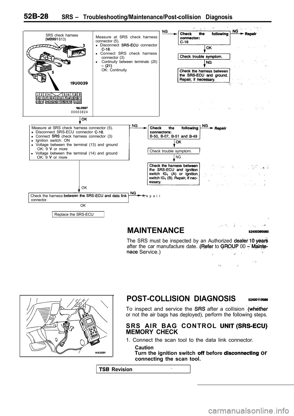
0 0 0 0 3 8 2 4Measure at SRS check harness
connector (5). l Disconnect
connector
l Connect SRS check harness
connector (3)
l
Continuity between terminals (20)
OK: Continuity
Measure at SRS check harness connector (5).
l Disconnect SRS-ECU connector
l Connect check harness connector (3)
l Ignition switch: ON
l Voltage between the terminal (13) and ground
OK: 9
or more
l Voltage between the terminal (14) and ground
OK: 9
or more
Check trouble symptom.
NG
OK
Check the harness R e p a i r connector.
OK
Replace the SRS-ECU
MAINTENANCE
,
The SRS must be inspected by an Authorized
after the car manufacture date. to 00
Service.)
POST-COLLISION DIAGNOSIS
To inspect and service the after a collision
or not the air bags has deployed), perform the foll owing steps.
S R S A I R B A G C O N T R O L
MEMORY CHECK
1. Connect the scan tool to the data link connector .
Caution
Turn the ignition switch before or
connecting the scan tool.
Revision
Page 2025 of 2103

SRS Post-collision Diagnosis
2. Read (and write down) all displayed diagnostic trouble
codes. (Refer to
NOTE
If the battery power supply has’ been disconnected or
disrupted by the collision, the scan tool cannot communi-
cate with the SRS-ECU.
and, ‘if necessary, repair
the body wiring harness before proceeding further.
3.Read the service data (fault duration and times
the memory was erased) using the Scan
NOTE
lMaximum stored period: 9999 minutes (approximately
7 days)
lMaximum number of times to be 250
4.Erase the diagnostic trouble codes, then wait 5 sec onds
or more, read and write down all displayed diagnost ic
trouble codes. (Refer to
REPAIR PROCEDURE
WHEN AIR BAG DEPLOYS IN A COLLISION.
1. Replace the following parts with new ones. l SRS air bag control unit (SRS-ECU) (Refer
l Air bag modules (Refer to
2.Check the following parts, and replace if any malfu nctions
are present.
l Clock spring (Refer to
l Steering wheel, steering column and intermediate
joint
(1) Check wiring harness (built, into’ steering whe el)
and connectors for damage, and terminals for
deformation.
(2) install air bag module to check fit or alignment
with steering wheel,.
(3) Check steering wheel for noise, binds or difficult
operation and excessive free play.
3. Check harnesses for binding, connectors for dama ge,
poor connections, and terminals for deformation.
(Refer to
WHEN AIR BAG DOES NOT IN LOW-SPEED
COLLISION.
Check the SRS components.
If the SRS components are showing any visible damag e such
as dents, cracks, or deformation, replace them with new ones.
Concerning parts removed for inspection, replacemen t
new parts and cautionary points for working, to
appropriate COMPONENT SERVICE,
TSB Revision
Page 2026 of 2103
SRS Post-collision Diagnosis/Component Service
Air Bag Control Unit (SRS-ECU)
1. Check SRS-ECU case and brackets for dents, crack s
or deformation.
2. Check connector for damage, and terminals for
deformation.
0 0 0 0 0 0 5 4
side>Inflator case
Air Bag Module
1. Check pad cover for dents, cracks or deformation .
2. Check for connector damage, deformed terminal, a nd
binding harness.
3. Check air bag inflator case for dents, cracks or
deformation.
4.Install air bag module to steering wheel to check fit or
alignment with the wheel.
Page 2028 of 2103
SRS SRS Air Ban Control Unit (SRS-ECU)
SRS AIR BAG CONTROL UNIT (SRS-ECU) 52400210076
Caution
Never attempt to disassemble or repair the
SRS-ECU. If. faulty, replace it.
2.Do not drop or subject the SRS-ECU to
pact or vibration. If dents, cracking,
formation, or rust are discovered on the
SRS-ECU, replace it with a new SRS-ECU.
Discard the old one. 3. After deployment of
air, bags, replace
the
with, a
4.Never use an on or near
ECU, and use only the special test equip
ment described on
REMOVAL AND INSTALLATION
Operation
l Turn the ignition key to the “LOCK” position
Removal steps
l Post-installation inspection
1. Negative battery cable connec-
tion2. Inner box
3. SRS-ECU and harness connector
connection
4.5. Shift lever knob 6.Ashtray
7. Center console panel Floor console assembly9.Bracket
TSB Revision
Page 2029 of 2103

SRS SRS Air BagControl Unit (SRS-ECU)
Insulating tape
Battery cable
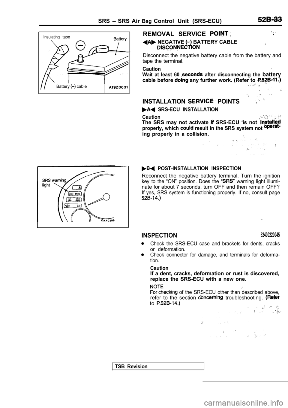
REMOVAL SERVICE
NEGATIVE BATTERY CABLE
.
Disconnect the negative battery cable from the batt ery and
tape the terminal.
Caution
Wait at least 60 after disconnecting the battery
cable before any further work. (Refer to ,
INSTALLATION POINTS.
SRS-ECU INSTALLATION
Caution
The SRS may not activate SRS-ECU ‘is not
properly, which result in the SRS system not
ing properly in a collision.
POST-INSTALLATION INSPECTION
Reconnect the negative battery terminal. Turn the i gnition
key to the “ON” position. Does the warning light illumi-
nate for about 7 seconds, turn OFF and then remain OFF?
If yes, SRS system is functioning properly. If no, consult page
INSPECTION52400220045
Check the SRS-ECU case and brackets for dents, crac ks
or deformation.
Check connector for damage, and terminals for defor ma-
tion.
Caution
If a dent, cracks, deformation or rust is discovered,
replace the SRS-ECU with a new one.
of the SRS-ECU other than described above,
refer to the section troubleshooting.
to,
TSB Revision