1990 MITSUBISHI SPYDER ECU
[x] Cancel search: ECUPage 2039 of 2103
SRS Air Bag Module Disposal Procedures
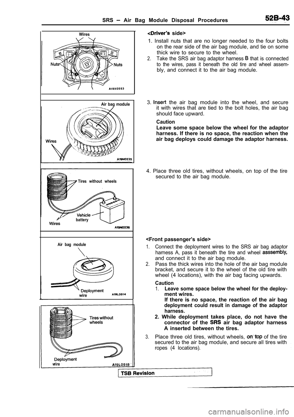
Wires
Air bag module
Tires without wheels
battery
Air bag module
wire
side>
1. Install nuts that are no longer needed to the fo ur bolts
on the rear side of the air bag module, and tie on some
thick wire to secure to the wheel.
2.Take the SRS air bag adaptor harness that is connected
to the wires, pass it beneath the old tire and whee l assem-
bly, and connect it to the air bag module.
3.
the air bag module into the wheel, and secure
it with wires that are tied to the bolt holes, the air bag
should face upward.
Caution
Leave some space below the wheel for the adaptor
harness. If there is no space, the reaction when th e
air bag deploys could damage the adaptor harness.
4. Place three old tires, without wheels, on top of the tire
secured to the air bag module.
1.Connect the deployment wires to the SRS air bag ada ptor
harness A, pass it beneath the tire and wheel
and connect it to the air bag module.
2.Pass the thick wires into the hole of the air bag m odule
bracket, and secure it to the wheel of the old tire with
wheel (4 locations), with the air bag facing upward s.
Caution
1.Leave some space below the wheel for the deploy-
ment wires.
If there is no space, the reaction of the air bag
deployment could result in damage of the adaptor
harness.
2. While deployment takes place, do not have the connector of the
air bag adaptor harness
A inserted between the tires.
3.Place three old tires, without wheels, of the tire
secured to the air bag module, and secure all tires with
ropes (4 locations).
wire
Page 2041 of 2103
CONTENTS
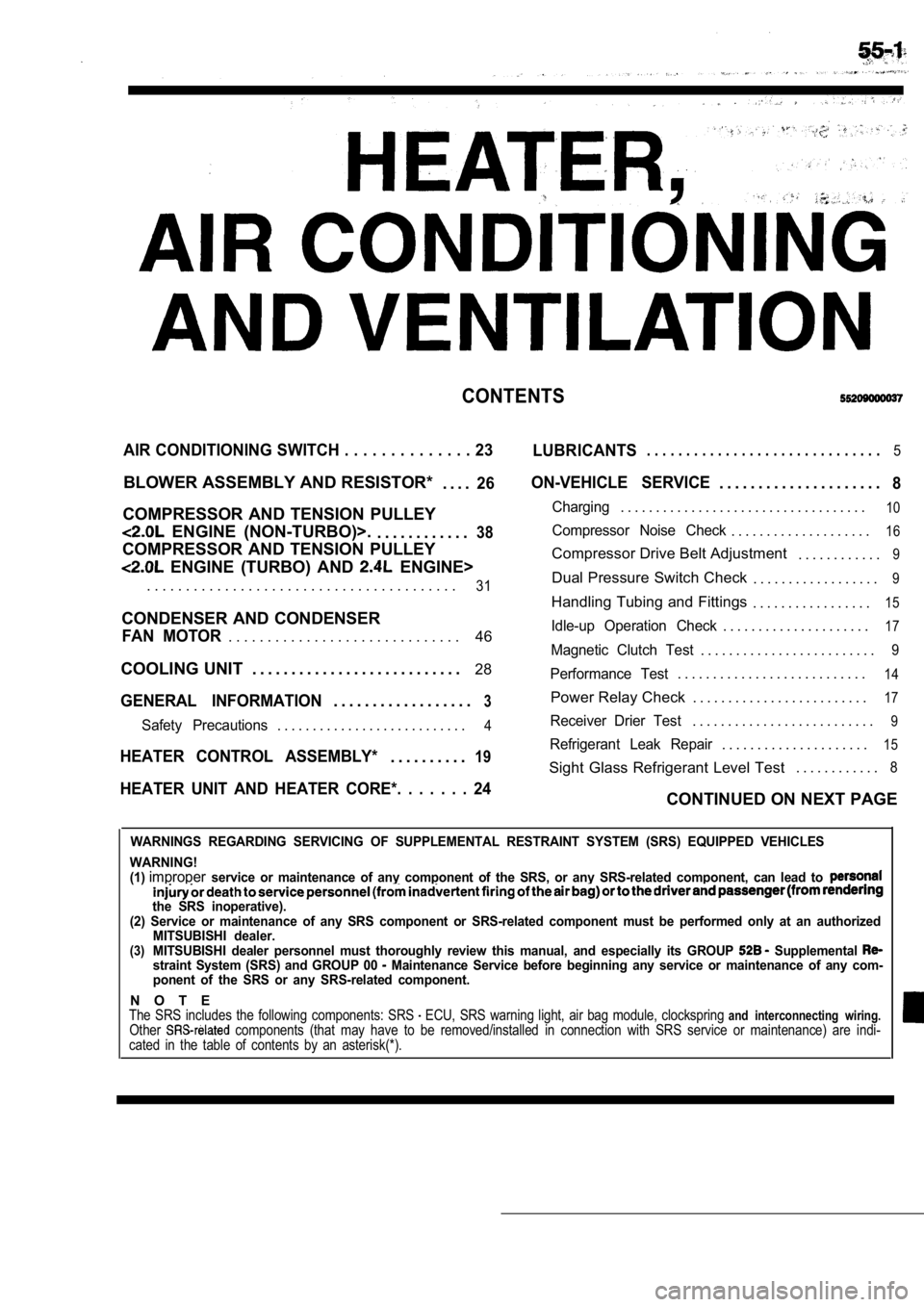
AIR CONDITIONING SWITCH . . . . . . . . . . . . . . 23
LUBRICANTS. . . . . . . . . . . . . . . . . . . . . . . . . . . . . .5
BLOWER ASSEMBLY AND RESISTOR*
. . . .26
COMPRESSOR AND TENSION PULLEY
ENGINE (NON-TURBO)>.. . . . . . . . . . . .38
COMPRESSOR AND TENSION PULLEY
ENGINE (TURBO) AND ENGINE>
ON-VEHICLE SERVICE. . . . . . . . . . . . . . . . . . . . .8
Charging. . . . . . . . . . . . . . . . . . . . . . . . . . . . . . . . . . .10
Compressor Noise Check. . . . . . . . . . . . . . . . . . . .16
Compressor Drive Belt Adjustment . . . . . . . . . . . .9
. . . . . . . . . . . . . . . . . . . . . . . . . . . . . . . . . . . . . . . .31Dual Pressure Switch Check. . . . . . . . . . . . . . . . . .9
Handling Tubing and Fittings. . . . . . . . . . . . . . . . .15
CONDENSER AND CONDENSER
46Idle-up Operation Check. . . . . . . . . . . . . . . . . . . . .17FAN MOTOR. . . . . . . . . . . . . . . . . . . . . . . . . . . . . .Magnetic Clutch Test. . . . . . . . . . . . . . . . . . . . . . . . .9
COOLING UNIT . . . . . . . . . . . . . . . . . . . . . . . . . . . 28
GENERAL INFORMATION3. . . . . . . . . . . . . . . . . .
Performance Test. . . . . . . . . . . . . . . . . . . . . . . . . . .14
Power Relay Check . . . . . . . . . . . . . . . . . . . . . . . . .17
Safety Precautions. . . . . . . . . . . . . . . . . . . . . . . . . . .4Receiver Drier Test. . . . . . . . . . . . . . . . . . . . . . . . . .9
. . . . . . . . . . . . . . . . . . . . .15HEATER CONTROL ASSEMBLY*19Refrigerant Leak Repair. . . . . . . . . .
Sight Glass Refrigerant Level Test . . . . . . . . . . . .8
HEATER UNIT AND HEATER CORE*. . . . . . . 24CONTINUED ON NEXT PAGE
WARNINGS REGARDING SERVICING OF SUPPLEMENTAL RESTRA
INT SYSTEM (SRS) EQUIPPED VEHICLES
WARNING!
(1)
improperservice or maintenance of any component of the SRS, or any SRS-related component, can lead to
the SRS inoperative).
(2) Service or maintenance of any SRS component or SRS-related component must be performed only at an authorized
MITSUBISHI dealer.
(3)MITSUBISHI dealer personnel must thoroughly review this manual, and especially its GROUP Supplemental straint System (SRS) and GROUP 00 Maintenance Service before beginning any service or maintenance of any com-
ponent of the SRS or any SRS-related component.
N O T EThe SRS includes the following components: SRS ECU, SRS warning light, air bag module, clocksprin g and interconnecting wiring.Other components (that may have to be removed/installed in connection with SRS service or maintenance) are indi-
cated in the table of contents by an asterisk(*).
Page 2043 of 2103
HEATER, AIR
AND VENTILATION General Information
GENERAL INFORMATION
The heater system uses a two-way-flow full-air-mixThe A/C system is basically the same as the
system that features high performance and lowtional system, but a new refrigerant system
operating noise, and includes an independent facebeen adopted as a response to
air blowing function and a air bypass function.use of chlorofluorocarbons. ,
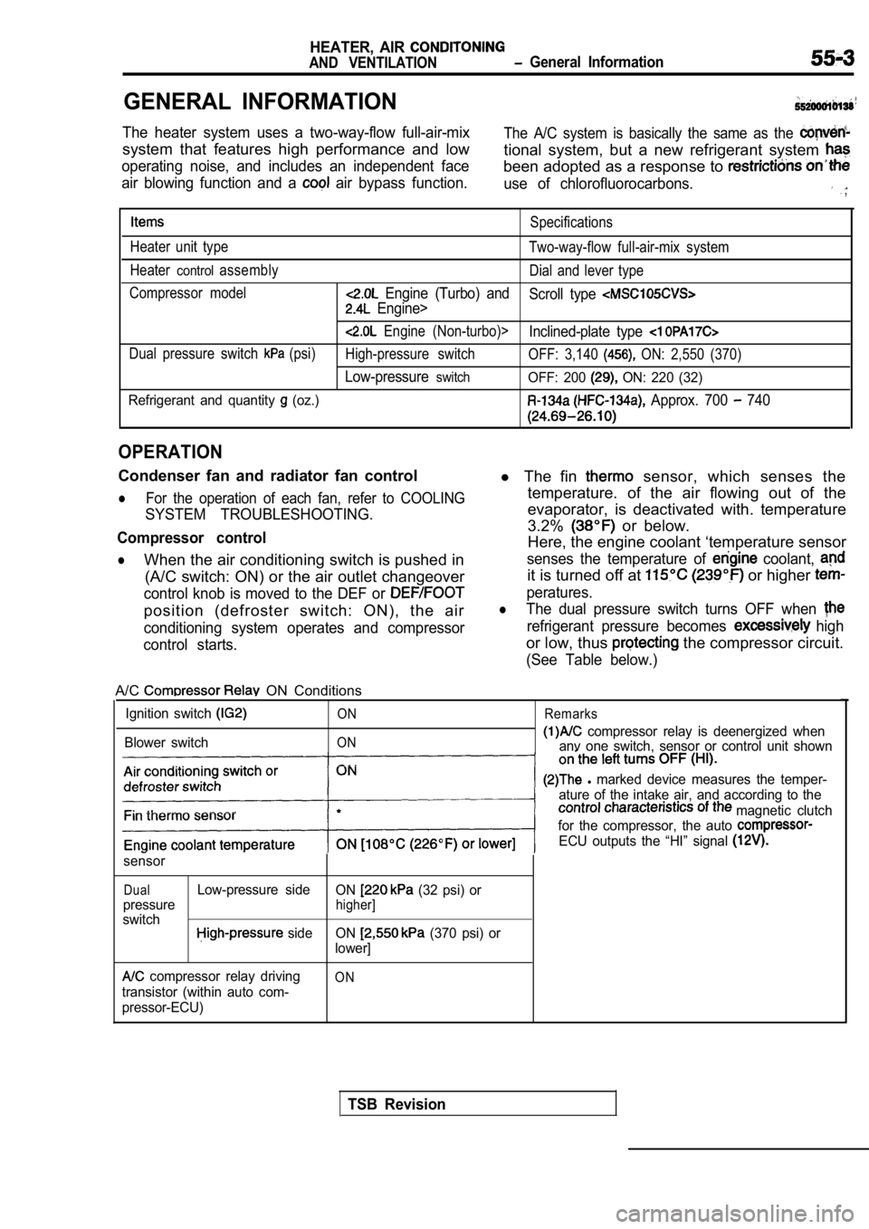
Specifications
Heater unit type Two-way-flow full-air-mix system
Heater
controlassembly Dial and lever type
Compressor model
Engine (Turbo) and Scroll type
Engine>
Engine (Non-turbo)>Inclined-plate type
Dual pressure switch (psi)High-pressure switch OFF: 3,140 ON: 2,550 (370)
Low-pressureswitchOFF: 200 ON: 220 (32)
Refrigerant and quantity
(oz.) Approx. 700 740
OPERATION
Condenser fan and radiator fan control
lFor the operation of each fan, refer to COOLING
SYSTEM TROUBLESHOOTING.
Compressor control
lWhen the air conditioning switch is pushed in (A/C switch: ON) or the air outlet changeover
control knob is moved to the DEF or
position (defroster switch: ON), the air
conditioning system operates and compressor
control starts.
l The fin sensor, which senses the
temperature. of the air flowing out of the
evaporator, is deactivated with. temperature
3.2%
or below.
Here, the engine coolant ‘temperature sensor
senses the temperature of coolant,
it is turned off at or higher
peratures.
lThe dual pressure switch turns OFF when
refrigerant pressure becomes high
or low, thus the compressor circuit.
(See Table below.)
A/C ON Conditions
Ignition switch
Blower switch
ON
ON Remarks
compressor relay is deenergized when
anv one switch, sensor or control unit shown
l marked device measures the temper-
ature of the intake air, and according to the
magnetic clutch
for the compressor, the auto
ECU outputs the “HI” signal
sensor
DualLow-pressure side ON (32 psi) or
pressure
higher]
switch side ON (370 psi) or
lower]
compressor relay driving
transistor (within auto com-
pressor-ECU)ON
TSB Revision
Page 2046 of 2103

HEATER, AIR
AND VENTILATION Troubleshooting
TROUBLESHOOTING
PROCEDURES
Trouble
symptom
When the ignitior
switch is “ON”,
the
does not
operate.
conditioning
does not
when
he air outlet
knob is
noved to the
or
position. Problem cause
compressor clutch relay
is defective
Magnetic clutch is defective
Refrigerant leak or overfilling
of refrigerant
Dual pressure switch is defec-
tive
A/C switch is defective Blower switch is defective
Fin
sensor is defective
Refrigerant temperature switch
is defective
Engine (Tur-
bo) and
Engine>
Automatic compressor-ECM
is defective
Revolution pick up sensor is
defective
Engine (Non-turbo)>
A/C compressor relay is de-
fective
1
Dual pressure switch is defec-
tive
Defroster switch is defective
TSB Revision
Magnetic clutch is defective
Refrigerant leak or overfilling
of refrigerant Remedy
Reference ReferencepagepageEngine
Engine(Non-turbo) (Turbo) Engine
Replace A/C compressor clutch 55-1855-18
relay
Replace the armature plate, rotor55-34
or clutch coil
Replenish the refrigerant, repair
0
the leak or take out some of therefrigerant
Replace the dual pressure switch 55-45
Replace the A/C switch 55-2355-23
Replace the blower switch55-22 55-22
Replace the fin sensor
Replace the refrigerant tempera-
ture switch
Replace the automatic
Replace the revolution pick up
sensor
55-26
Replace A/C compressor clutch55-18
relay
Replace the armature plate, rotor55-34
or clutch coil
Replenish the refrigerant, repair
the leak or take out some of the
refrigerant
Replace the dual pressure switch55-45
the defroster switch55-22 55-22
the blower switch55-225 5 - 2 2
temperature Replace the refrigerant tempera-
is defective
ture switch
compressor-ECU isReplace the automatic 55-26
sor-ECU
pick up sensor is
Replace the revolution pick up
sensor Engine
Page 2060 of 2103
AIR ,
AND VENTILATION Heater
R E M O V A L
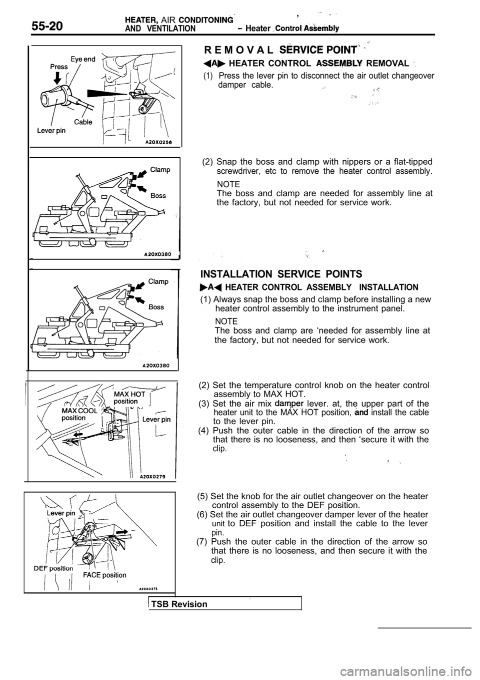
HEATER CONTROL REMOVAL
(1)Press the lever pin to disconnect the air outlet changeover
damper cable.
(2) Snap the boss and clamp with nippers or a flat- tipped
screwdriver, etc to remove the heater control assem bly.
NOTE
The boss and clamp are needed for assembly line at
the factory, but not needed for service work.
INSTALLATION SERVICE POINTS
HEATER CONTROL ASSEMBLY INSTALLATION
(1) Always snap the boss and clamp before installin g a new
heater control assembly to the instrument panel.
NOTE
The boss and clamp are ‘needed for assembly line at
the factory, but not needed for service work.
(2) Set the temperature control knob on the heater control
assembly to MAX HOT.
(3) Set the air mix
lever. at, the upper part of the
heater unit to the MAX HOT position, install the cable
to the lever pin.
(4) Push the outer cable in the direction of the ar row so
that there is no looseness, and then ‘secure it wit h the
clip.
,
(5) Set the knob for the air outlet changeover on the heater
control assembly to the DEF position.
(6) Set the air outlet changeover damper lever of t he heater
unit to DEF position and install the cable to the lever
pin.
(7) Push the outer cable in the direction of the ar row so
that there is no looseness, and then secure it with the
clip.
TSB Revision
Page 2061 of 2103
Air-recirculation position
HEATER, AIR
AND VENTILATION Heater Control Assembly
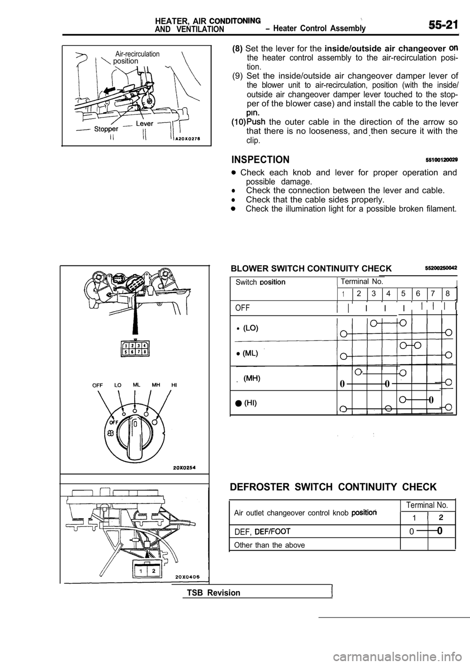
(8)Set the lever for the inside/outside air changeover
the heater control assembly to the air-recirculatio n posi-
tion.
(9) Set the inside/outside air changeover damper le ver of
the blower unit to air-recirculation, position (with the inside/
outside air changeover damper lever touched to the stop-
per of the blower case) and install the cable to the lever
the outer cable in the direction of the arrow so
that there is no looseness, and then secure it with the
.
clip.
INSPECTION
Check each knob and lever for proper operation and
possible damage.
lCheck the connection between the lever and cable.
lCheck that the cable sides properly.
Check the illumination light for a possible broken filament.
BLOWER SWITCH CONTINUITY CHECK
Switch Terminal No.I
12 3 4 5 6 7 8
OFF I I I
.0 0
0
TSB Revision
DEFROSTER SWITCH CONTINUITY CHECK
Terminal No.Air outlet changeover control knob 1
DEF,
Other than the above
00
Page 2063 of 2103
HEATER, AIR
AND VENTILATION Air Conditioning Switch
AIR CONDITIONING SWITCH
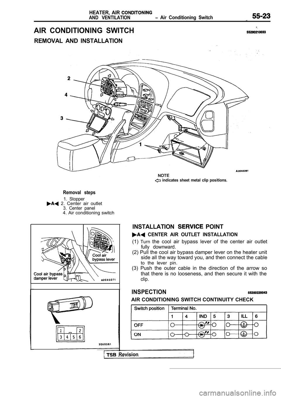
REMOVAL AND INSTALLATION
Removal steps
1. Stopper 2. Center air outlet3. Center panel4. Air conditioning switch
indicates sheet metal clip positions.
I Revision
INSTALLATION POINT
CENTER AIR OUTLET INSTALLATION
(1)Turn the cool air bypass lever of the center air outlet
fully downward.
(2) Pull the cool air bypass damper lever on the he ater unit
side all the way toward you, and then connect the c able
to the lever pin.
(3) Push the outer cable in the direction of the ar row so
that there is no looseness, and then secure it with the
clip.
INSPECTION
AIR CONDITIONING SWITCH CONTINUITY CHECK
Page 2064 of 2103
HEATER, AIR
AND VENTILATION Heater Unit and Heater Core
HEATER UNIT AND HEATER CORE
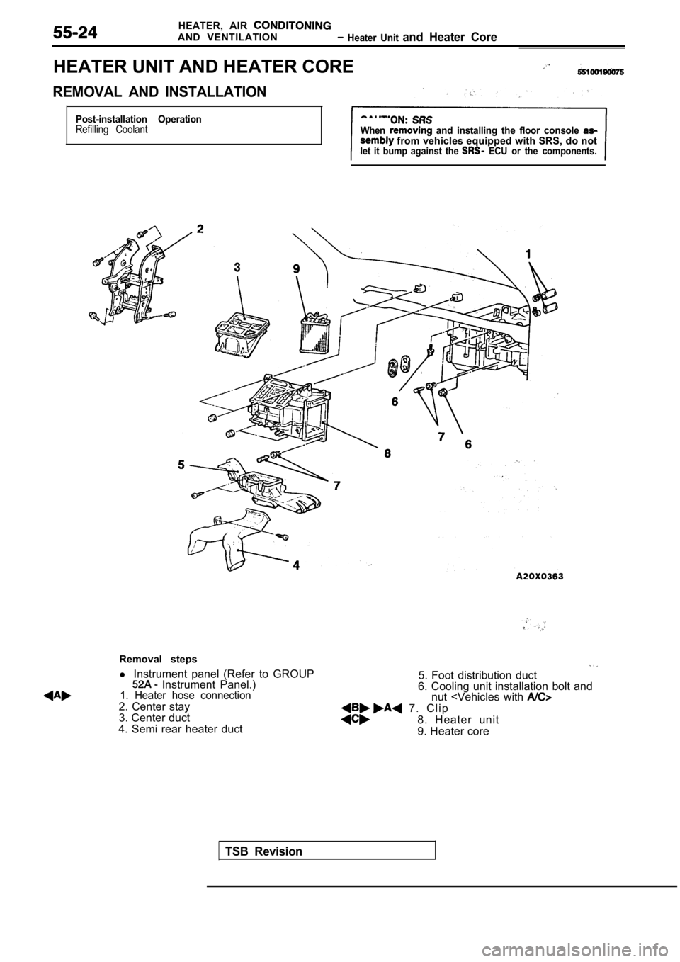
REMOVAL AND INSTALLATION
Post-installation OperationRefilling CoolantWhen and installing the floor console from vehicles equipped with SRS, do notlet it bump against the ECU or the components.
TSB Revision
Removal steps
l Instrument panel (Refer to GROUP
Instrument Panel.)1. Heater hose connection2. Center stay
3. Center duct
4. Semi rear heater duct
5. Foot distribution duct
6. Cooling unit installation bolt and nut
8. Heater unit
9. Heater core