Page 1990 of 2103
INTERIOR Front Seat Belt
FRONT SEAT BELT
REMOVAL AND INSTALLATION
3
33
000053
JunctionBlock
1) Metal clip position2) Resin clip position
Front outer seat belt removal steps
l Rear seat cushion
(Refer to
1. Quarter trim, lower
(Refer to
2. Coat hanger
3. Rear seat belt sash guide cover
4. Rear seat belt anchor plate
5. Front seat belt sash guide cover
6. Front seat belt anchor plate
7. Quarter trim, upper
(Refer to
8. Adjustable seat belt anchor
9. Fuel harness protector Front Inner seat
removal ‘steps
l Front seat
(Refer to 12. Harness connector (driver’s side)
13. Front seat hinge cover
14. Front inner seat belt
ETACS-ECU (Seat belt warninglight timer and buzzer) removal
15. ETACS-ECU (Refer to GROUP 54
Ignition Switch.)
10. Front outer seat belt 11. Seat belt retractor cover
TSB Revision
Page 1991 of 2103
INTERIOR Front Seat Belt
REMOVAL AND INSTALLATION
44 Nm 33
33
JunctionBlock
Front outer seat belt removal stepsl Quarter trim, lower (Refer to
1. Front outer seat belt
Front inner seat belt removal steps
l
a s s e m b l y ( R e f e r t o
.
2. Harness connector (Driver’s seat)
3. Front seat hinge cover
4. Front inner seat belt
0 0 0 0 5 3 1 7
ETACS-ECU (Seat belt warning
light timer and buzzer) removal 5. ETACS-ECU (Refer to GROUP 54
Ignition Switch.)
TSB Revision
Page 1997 of 2103
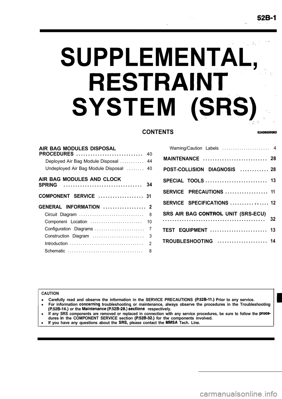
SUPPLEMENTAL,
SYSTEM
CONTENTS
AIR BAG MODULES DISPOSAL
PROCEDURES. . . . . . . . . . . . . . . . . . . . . . . . . . . .40
Deployed Air Bag Module Disposal . . . . . . . . . . .
44
Undeployed Air Bag Module Disposal . . . . . . . .40
AIR BAG MODULES AND CLOCK
SPRING. . . . . . . . . . . . . . . . . . . . . . . . . . . . . . . . .34
COMPONENT SERVICE
. . . . . . . . . . . . . . . . . . .31
GENERAL INFORMATION. . . . . . . . . . . . . . . . . .2
Circuit Diagram. . . . . . . . . . . . . . . . . . . . . . . . . . . . . .8
Componeni Location. . . . . . . . . . . . . . . . . . . . . . . .10
Configuration Diagrams. . . . . . . . . . . . . . . . . . . . . . .7
Construction Diagram. . . . . . . . . . . . . . . . . . . . . . . .3
Introduction. . . . . . . . . . . . . . . . . . . . . . . . . . . . . . . . . .2
Schematic. . . . . . . . . . . . . . . . . . . . . . . . . . . . . . . . . . .8
Warning/Caution Labels. . . . . . . . . . . . . . . . . . . . . . 4
MAINTENANCE. . . . . . . . . . . . . . . . . . . . . . . . . . .28
POST-COLLISION DIAGNOSIS
. . . . . . . . . . . .28
SPECIAL TOOLS. . . . . . . . . . . . . . . . . . . . . . . . . .13
SERVICE PRECAUTIONS. . . . . . . . . . . . . . . . . .11
SERVICE SPECIFICATIONS. . . . . . . . . .. . . .12
SRS AIR BAG UNIT (SRS-ECU)
. . . . . . . . . . . . . . . . . . . . . . . . . . . . . . . . . . . . . . . . . . .
32
TEST EQUIPMENT. . . . . . . . . . . . . . . . . . . . . . . .13
TROUBLESHOOTING. . . . . . . . . . . . . . . . . . . . .14
CAUTION
lCarefully read and observe the information in the S ERVICE PRECAUTIONS Prior to any service.lFor information troubleshooting or maintenance, always observe the procedures in the Troubleshooting or the respectively.
lIf any SRS components are removed or replaced in co nnection with any service procedures, be sure to follow the dures the COMPONENT SERVICE section for the components involved.lIf you have any questions about the please contact the Tech. Line.
Page 1998 of 2103
SRS General Information
GENERAL INFORMATION
INTRODUCTION
The Supplemental Restraint System (SRS) is
signed to supplement the driver’s and front passen-
ger’s seat belts to help reduce the risk or severity
of injury to the driver and front passenger by acti vat-
ing and deploying both air bags in certain frontal
collisions.
The SRS consists of: two air bag modules; one
located in the center of the steering wheel and
another one located above the glove box, which
contains. the folded air bag and an inflator unit;
the SRS air bag control unit (SRS-ECU) located
under the floor console assembly, which monitors
the system, and which contains a safing
sensor
and analog
sensor; an SRS warning light located
on the instrument panel, which indicates the
tional status of the SRS; spring-interconnec-
tion located within the the
It is not until the SRS-ECU in response to the outp ut
signal from the analog sensor, finds it necessary
to ignite the air bag, and the safing sensor is
caused to be ON that the SRS deploys the air
bag.
Only authorized service personnel should do work
on or around SRS components. Those service per-
sonnel should read this manual carefully before
starting any such work. Extreme care must be used
when servicing the SRS, to avoid
to the ser-
vice personnel (by inadvertent deployment of the
air bag) or to driver (by rendering the SRS inopera -
tive).
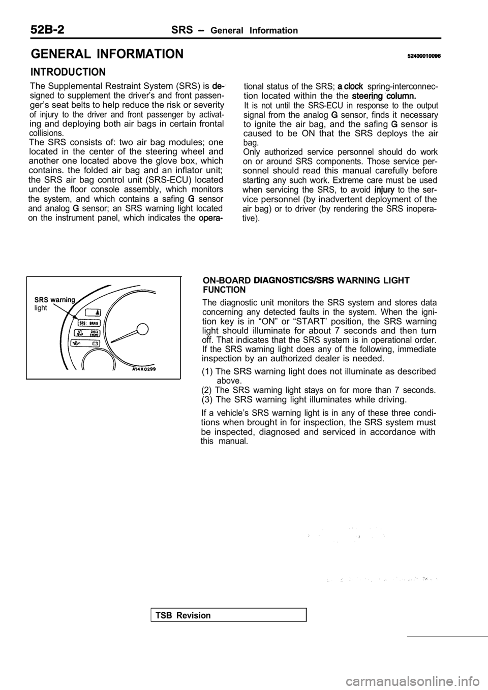
SRSlight
ON-BOARD WARNING LIGHT
FUNCTION
The diagnostic unit monitors the SRS system and sto res data
concerning any detected faults in the system. When the igni-
tion key is in “ON” or “START’ position, the SRS wa rning
light should illuminate for about 7 seconds and the n turn
off. That indicates that the SRS system is in operational order.
If the SRS warning light does any of the following, immediate
inspection by an authorized dealer is needed.
(1) The SRS warning light does not illuminate as de scribed
above.
(2) The SRS warning light stays on for more than 7 seconds.
(3) The SRS warning light illuminates while driving.
If a vehicle’s SRS warning light is in any of these three condi-
tions when brought in for inspection, the SRS syste m must
be inspected, diagnosed and serviced in accordance with
this manual.
TSB Revision
Page 1999 of 2103
SRS General
CONSTRUCTION DIAGRAM
VEHICLE IDENTIFI-CATION CODE
CHART PLATE
Air
module
SRS warning light
SRS-ECU(incorporated safing sensor
and analog sensor)
NOTEThis construction diagram displays the general view of the SRS components.
For details, refer to “Schematic” “Configuration Diagrams” and “Circuit Diagram”
TSB Revision
Page 2007 of 2103
SRS Service Precautions
SERVICE PRECAUTIONS52400020092
1. In order to avoid injury to yourself or others
from accidental deployment of the air bag during
servicing, read and carefully follow all the
cautions and procedures described in this
manual.
2. Do not use any electrical test equipment on
or near SRS components, except those
fiedon and
Never use an analog ohmmeter.
3.Never Attempt to Repair the Following
ponents:
SRS Air Bag Control Unit (SRS-ECU)
Clock Spring
Air Bag Module If any of these components are diagnosed as
faulty, they should only be replaced, in
dance with the COMPONENT SERVICE
dures in this manual, starting at page
4. Do not attempt repair the wiring harness
connectors of the SRS. any of the connectors
are diagnosed as faulty, replace the
harness. If the wires are diagnosed asfaulty,
replace or repair the wiring harness according
to the following
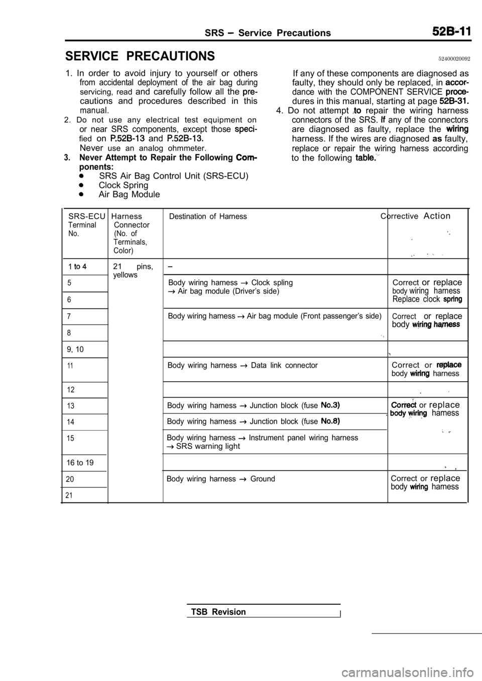
SRS-ECU HarnessDestination of HarnessCorrective A c t i o n
TerminalConnector
No.(No. of
Terminals,
Color)
121 pins,
yellows5Body wiring harness Clock splingCorrector replace
Air bag module (Driver’s side)bodywiring harness
6Replace clock
7Body wiring harness Air bag module (Front passenger’s side)Corrector replace
body
8
9, 10
11Body wiring harness Data link connectorCorrect or
body harness
12
13
14
15
Body wiring harness Junction block (fuse
Body wiring harness Junction block (fuse
Body wiring harness Instrument panel wiring harness
SRS warning light .
or
replace. harness
16 to 19 ,
20
21
Body wiring harness GroundCorrect or replace
body harness
TSB RevisionI
Page 2008 of 2103
SRS Service Precautions/Service Specifications
5.
6.
7.
a.
9.
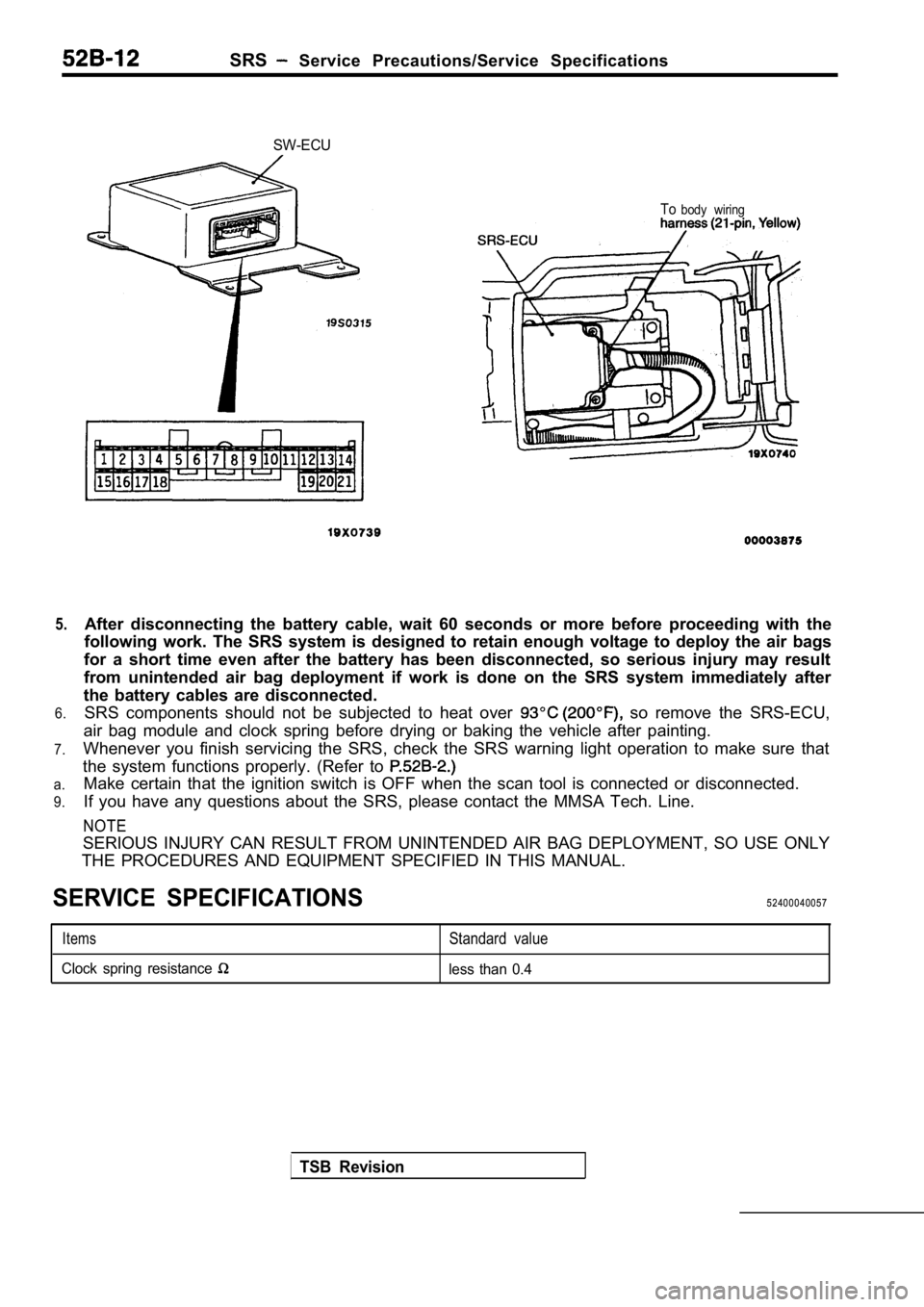
SW-ECU
Tobody wiring
After disconnecting the battery cable, wait 60 seco nds or more before proceeding with the
following work. The SRS system is designed to retai n enough voltage to deploy the air bags
for a short time even after the battery has been di sconnected, so serious injury may result
from unintended air bag deployment if work is done on the SRS system immediately after
the battery cables are disconnected. SRS components should not be subjected to heat over
so remove the SRS-ECU,
air bag module and clock spring before drying or ba king the vehicle after painting.
Whenever you finish servicing the SRS, check the SR S warning light operation to make sure that
the system functions properly. (Refer to
Make certain that the ignition switch is OFF when t he scan tool is connected or disconnected.
If you have any questions about the SRS, please con tact the MMSA Tech. Line.
NOTE
SERIOUS INJURY CAN RESULT FROM UNINTENDED AIR BAG D EPLOYMENT, SO USE ONLY
THE PROCEDURES AND EQUIPMENT SPECIFIED IN THIS MANU AL.
SERVICE SPECIFICATIONS52400040057
ItemsStandard value
Clock spring resistance less than 0.4
TSB Revision
Page 2011 of 2103
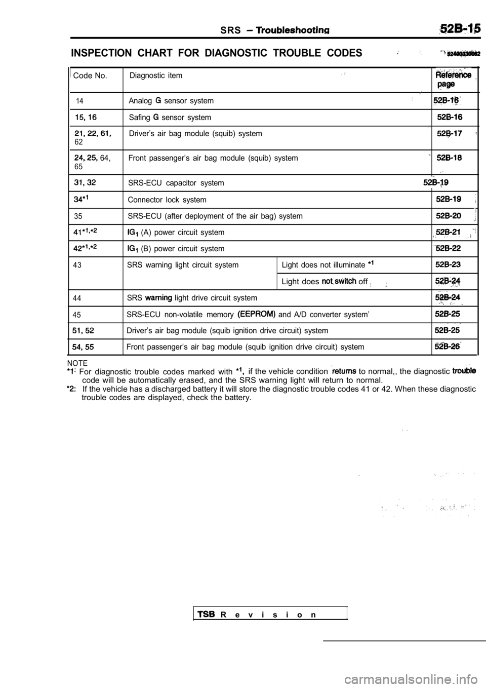
SRS
INSPECTION CHART FOR DIAGNOSTIC TROUBLE CODES
Code No.Diagnostic item
14Analog sensor system
Safing sensor system
Driver’s air bag module (squib) system
62
64, Front passenger’s air bag module (squib) system
65
SRS-ECU capacitor system
Connector lock system
35SRS-ECU (after deployment of the air bag) system
(A) power circuit system
(B) power circuit system
43SRS warning light circuit system Light does not illuminate
Light does off
44SRS light drive circuit system
45SRS-ECU non-volatile memory and A/D converter system’
Driver’s air bag module (squib ignition drive circuit) system
Front passenger’s air bag module (squib ignition dr ive circuit) system
NOTE
For diagnostic trouble codes marked with if the vehicle condition to normal,, the diagnostic
code will be automatically erased, and the SRS warn ing light will return to normal.
If the vehicle has a discharged battery it will store the diagnostic trouble codes 41 or 42. When thes e diagnostic
trouble codes are displayed, check the battery.
R e v i s i o n1