Page 1868 of 2103

BODY
T R O U B L E S Y M P T O M I N S P E C T I O N
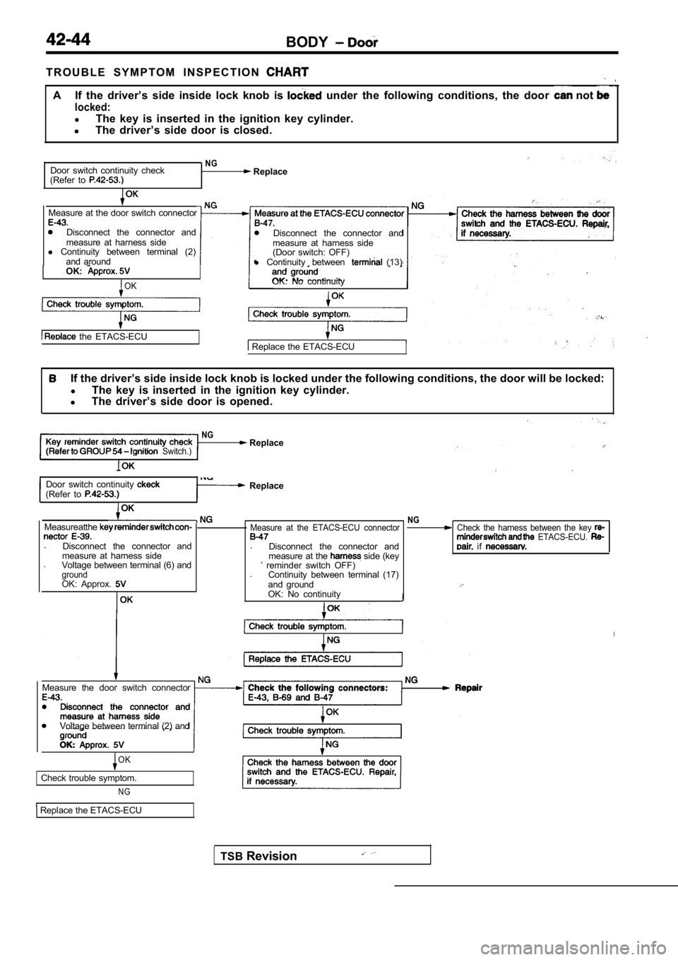
A If the driver’s side inside lock knob is under the following conditions, the door not
locked:
lThe key is inserted in the ignition key cylinder.
l The driver’s side door is closed.
Door switch continuity check
(Refer to
NG Replace
Measure at the door switch connector
Disconnect the connector and
measure at harness side
l Continuity between terminal (2)
and around
OK:
OK
the ETACS-ECU
NG
Disconnect the connector and
measure at harness side
(Door switch: OFF)
l Continuity between
(13)
OK: No continuity
Replace the ETACS-ECU
If the driver’s side inside lock knob is locked und er the following conditions, the door will be locke d:
l The key is inserted in the ignition key cylinder.
l The driver’s side door is opened.
NG Replace Switch.)
Door switch continuity (Refer to Replace
Measureatthe
.
Disconnect the connector and
measure at harness side
. Voltage between terminal (6) and
groundOK: Approx.
TSB Revision
Measure at the ETACS-ECU connector
.
Disconnect the connector and
measure at the side (key reminder switch OFF)
. Continuity between terminal (17)
and ground
OK: No continuity
NGCheck the harness between the key ETACS-ECU. if
Measure the door switch connector
Voltage between terminal (2) and
OK
Check trouble symptom.
NG
Replace the ETACS-ECU
Page 1869 of 2103
BODY Door
If the driver’s side inside lock knob is locked under the following conditions, the door can not
locked:lThe key is removed from the ignition key cylinder.
lThe driver’s side door is opened.
and
minder switch and the ETACS-ECU.
Replace the ETACS-ECU.
OK
NG Check the connectors:
between (4)
OK
Check trouble symptom.
N G
and
Replace the ETACS-ECU
TSB Revision
Page 1896 of 2103

42-72BODY Entry System
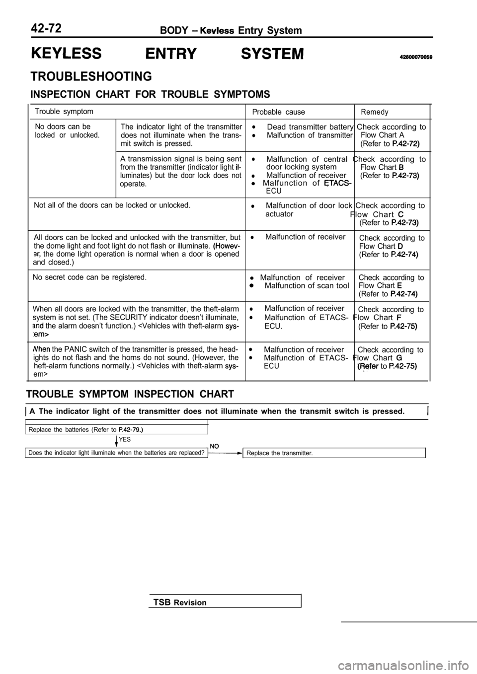
TROUBLESHOOTING
INSPECTION CHART FOR TROUBLE SYMPTOMS
Trouble symptomNo doors can be
locked or unlocked.
Probable causeRemedy
The indicator light of the transmitterl
does not illuminate when the trans-
Dead transmitter battery Check according to
lMalfunction of transmitter Flow Chart A
mit switch is pressed. (Refer to
A transmission signal is being sentl
from the transmitter (indicator light Malfunction of central Check according to
door locking system
Flow Chart
luminates) but the door lock does notlMalfunction of receiver
operate.l M a l f u n c t i o n o f (Refer to
ECU
Not all of the doors can be locked or unlocked.lMalfunction of door lock Check according to
actuatorF l o w C h a r t
(Refer to
All doors can be locked and unlocked with the trans mitter, butlMalfunction of receiver
the dome light and foot light do not flash or illuminate. Check according to
the dome light operation is normal when a door is openedFlow Chart
and closed.) (Refer to
No secret code can be registered.l
Malfunction of receiver
Malfunction of scan tool
Check according to
Flow Chart
(Refer to
When all doors are locked with the transmitter, the theft-alarmlMalfunction of receiver
system is not set. (The SECURITY indicator doesn’t illuminate,Check according tol
the alarm doesn’t function.)
alarm
Malfunction of ETACS- Flow Chart
ECU.
(Refer to
the PANIC switch of the transmitter is pressed, th e head-lMalfunction of receiverights do not flash and the horns do not sound. (How ever, theCheck according tol
heft-alarm functions normally.)
t-alarm
em>
Malfunction of ETACS- Flow Chart
ECU to
TROUBLE SYMPTOM INSPECTION CHART
A The indicator light of the transmitter does not illuminate when the transmit switch is pressed.
Replace the batteries (Refer to
YES
Does the indicator light illuminate when the batter ies are replaced?
Replace the transmitter.
TSB Revision
Page 1897 of 2103
S y s t e m
A transmission signal is being sent from transmitter (indicator
lock does not operate.. .
Can the doors be locked and unlocked with the key at the driver’s
Check the door locking system. (Refer to side door?,YES
Has the secret code been programmed correctly? l secret (Refer to
YES
Receiver terminal voltage check (Refer to Check the following
OK and 549
Check the following connectors:
and
N O T El :Carry when or or the code has been programmed
Not all of the doors can be locked or unlocked.I
Door lock actuator check (Refer to Replace the door lock actuator.
OK
N G
Check the following connectors:
If driver’s side door does not operate
and If side door does not and
OK
Check the trouble svmptom.
N G
Check and repair the harness between the ETACS-ECU and the door lock actuator of the door that will not operate.
Revision
Page 1898 of 2103

B O D Y Entry System
All doors can be locked and unlocked with the transmitter, but the dome light and foot light do not flash or illuminate. (However, the dome light operation is normal when a door is opened and
closed.)
NGMeasure at the receiver connector Replace the receiver.lDisconnect the connector and measure at the harness side.lSet the dome light switch in DOOR position, and then measurethe voltage between terminal (11) and ground.
OK: Battery positive voltage
OK
Check the following connectors: Repair a n d .OK
Check trouble symptom.
N G
Check the harnesses between the dome light and foot light and
the receiver. Repair, if necessary.
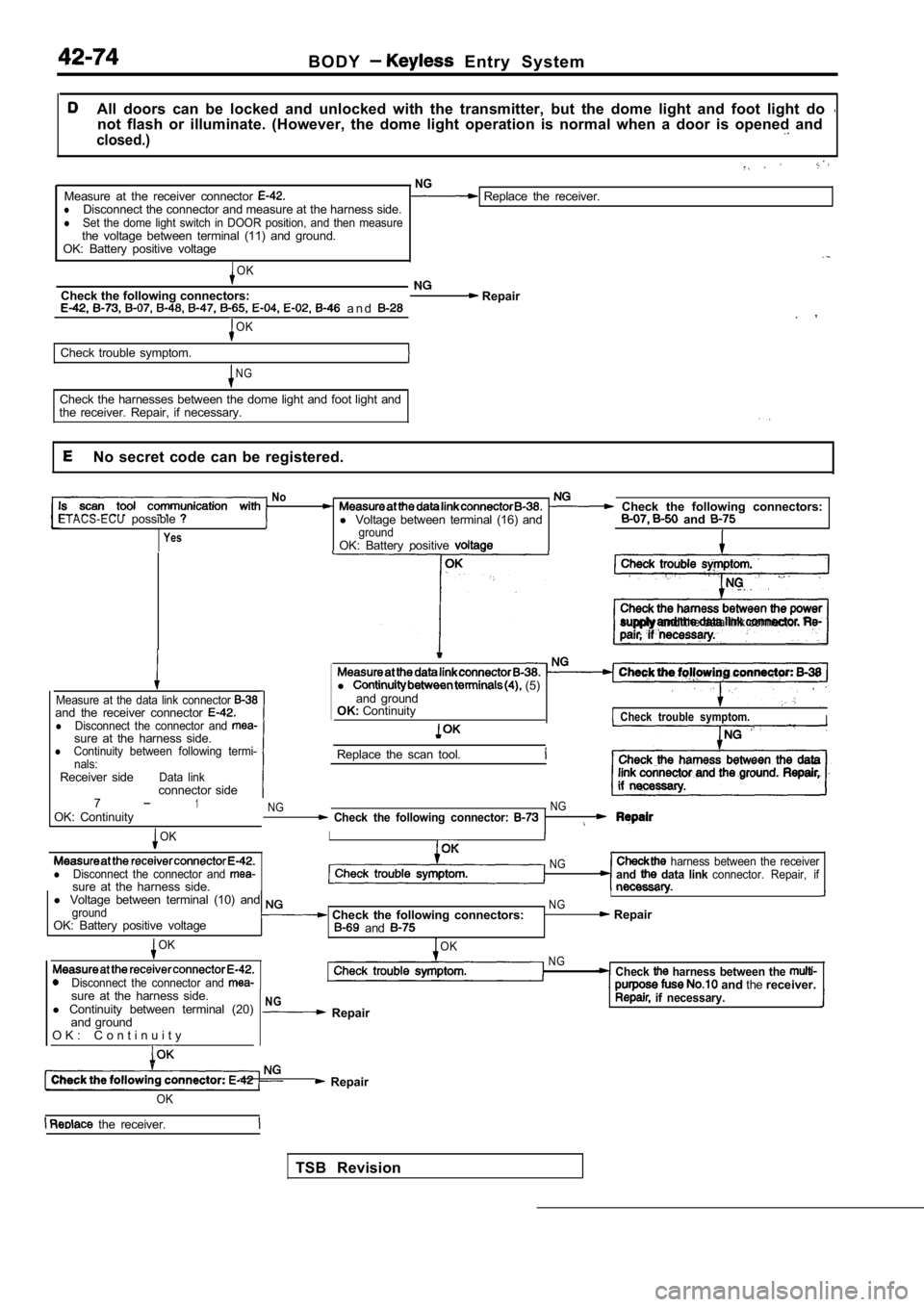
No secret code can be registered.
NoCheck the following connectors:ETACS-ECUpossiblel Voltage between terminal (16) and and
YesgroundOK: Battery positive
supply and the data link connector.
Measure at the data link connector and the receiver connector lDisconnect the connector and sure at the harness side.lContinuity between following termi-
nals:
Receiver sideData linkconnector side
l (5)
and ground
OK: Continuity
Check trouble symptom.I
Replace the scan tool.
71OK: ContinuityNG NG Check the following connector:
OKI
lDisconnect the connector and sure at the harness side.
NG harness between the receiverand data link connector. Repair, if
l
Voltage between terminal (10) and I
groundNG
OK: Battery positive voltage Check the following connectors: Repair and
OK
Disconnect the connector and
OKNGCheck harness between the and thereceiver.
sure at the harness side.
l Continuity between terminal (20)
and ground
O K : C o n t i n u i t y
NG Repair if necessary.
Repair
TSB Revision
OK
the receiver.
Page 1899 of 2103

B O D Y Entry System
When all doors are locked with the transmitter, the theft-alarm system is not set. (The SECURITY
indicator doesn’t illuminate, and the alarm doesn’t function.)
When all doors are locked with the key, is the theft-alarm systemCheck the theft-alarm to GROUP 54 set?
System.)
Yes ,
Check the following connectors: and NG Repair
OK
Check trouble symptom.
NG NG
Disconnect the receiver connector measure harnessCheck the harness wire between the receiver and ETA CS-ECU.side.l Voltage between the terminal (15) and ground
OK: (Pulse output)’
OK
Replace the receiver.1
NOTEl : Using an oscilloscope
When the PANIC switch of the transmitter is pressed , the headlights do not flash and the horns
do not sound. (However, the theft-alarm functions n ormally.)
with theft-alarm system>
[Comment]When the PANIC switch is pressed, the receiver sends a PANIC signal to ETACS-ECU. Then the ECU flashes the headlights and sounds
the horns intermittently for approx. three minutes.
The headlights and horns share an operation circuit with the theft-alarm system. Because of this, if the theft-alarm system functions normally,
the
harness between the receiver and the ETACS-ECU mav be defective.
N GCheck the operation of the theft-alarm system. (Refer to GROUP Carry out troubleshooting for the theft-alarm 54 Theft-alarm System.) 1’
Repair
OK
Check trouble 1
NG
harness
side.
l Voltage between the terminal (15) and ground
OK: (Pulse output)
OK
the receiver.
N GCheck the harness wire between the receiver and ETA CS-ECU.
NOTEl : Using an oscilloscope
TSB Revision
Page 1927 of 2103
BODY Electric Convertible Top
CONVERTIBLE TOP SWITCH
REMOVAL
42620240012
A N D I N S T A L L A T I O N
NOTE indicates the metal clip position.
Removal steps
1. Stopper 2. Center air outlet assembly3. Convertible top switch
REMOVAL SERVICE POINT
AIR OUTLET ASSEMBLY REMOVAL
Using the pry tool, carefully pry the assembly out of the
INSTALLATION SERVICE POINT
CENTER AIR OUTLET ASSEMBLY
INSTALLATION
(1) Turn the cool air bypass lever of the center ai r outlet
fully downward.
(2) Pull the cool air bypass damper lever on the heater unit
side fully toward you, then attach the cable to the pin
of the
(3) Push the outer cable in the direction of the ar row so
there is no looseness, then secure it with the clip.
TSB Revision
Page 1961 of 2103

INTERIOR Instrument Panel
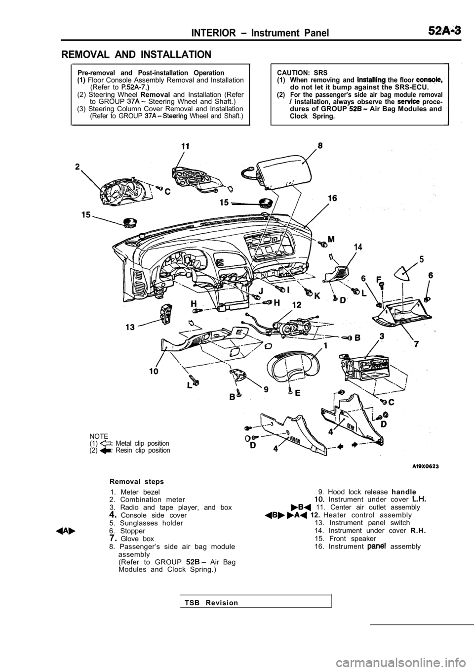
REMOVAL AND INSTALLATION
Pre-removal and Post-installation Operation Floor Console Assembly Removal and Installation(Refer to
(2) Steering Wheel Removaland Installation (Refer
to GROUP Steering Wheel and Shaft.)
(3) Steering Column Cover Removal and Installation
(Refer to GROUP Wheel and Shaft.)
CAUTION: SRS
(1) When removing and the floor do not let it bump against the SRS-ECU.(2)For the passenger’s side air bag module removal installation, always observe the proce-dures of GROUP Air Bag Modules andClock Spring.
14
5
NOTE
(1) Metal clip position
(2) Resin clip position
Removal steps
1. Meter bezel
2. Combination meter
3. Radio and tape player, and box
4. Console side cover
5. Sunglasses holder
6. Stopper 7. Glove box
8. Passenger’s side air bag module assembly(Refer to GROUP
Air Bag
Modules and Clock Spring.)
9. Hood lock release h a n d l e Instrument under cover 11. Center air outlet assembly 12. Heater control assembly
13. Instrument panel switch
14. Instrument under cover R . H .
15. Front speaker
16. Instrument
assembly
T S B R e v i s i o n