Page 1768 of 2103
PARKING BRAKES Parking . .
PARKING BRAKE LEVER
REMOVAL AND INSTALLATION
Operationl Floor Console Removal
(Refer to GROUP Floor Console.)
CAUTION: SRS1.When removing and installing the floor console,
do not let it bump against the SRS-ECU or other
components.
2. Before removal of to GROUP SRS-ECU.
Post-installationl Parking Brake Lever Stroke (Refer to P. 36-4.)
l Floor Console
(Refer to GROUP Floor
4
Section A-ASection ‘B-B
Removal steps
1. Adjusting nut
2. Parking brake stay
3. Bushing
4. Parking brake switch 5. Parking brake lever
TSB Revision
Page 1769 of 2103
PARKING BRAKES Parking Brake Cable
REMOVAL AND INSTALLATION
OperationFloor Console Removal(Refer to GROUP Floor Console.)
Post-installation Operation lParking Lever
l Installation (Refer to GROUP Floor Console.)
CAUTION: SRS1.When removing and installing the floor console,
do not let it bump against the SRS-ECU or other
components.
2. Before removal of SRS-ECU, refer to GROUP SRS-ECU.
Removal steps
1. Rear brake drum2. spring3.Auto adjuster assemblyShoe-to-shoe spring4.5.Retainer spring
6. Lever return’
7.Shoe8.Shoe spring
10.11.Shoe’ arid C l i p
12. brake
TSB Revision
Page 1770 of 2103
36-8PARKING BRAKES Parking Brake Cable
PARKING BRAKE CABLE BRAKE>
REMOVAL AND INSTALLATION.
Operationl Floor Removal(Refer to GROUP Floor Console.)Parking Brake Lever Stroke
(Refer to GROUP Floor Console.)
CAUTION: SRS1.When removing and the floor console,
do not let it bump against the SRS-ECU or other
components.
2. Before removal of SRS-ECU, refer to GROUP SRS-ECU.II .
l ,
1349-59 Nm36-43
Removal steps
1. Rear brake assembly
2. Rear brake disc
3. spring (rear) 4. Shoe-to-anchor spring (front) 5. Adjusting wheel spring
Page 1783 of 2103

STEERING On-vehicle
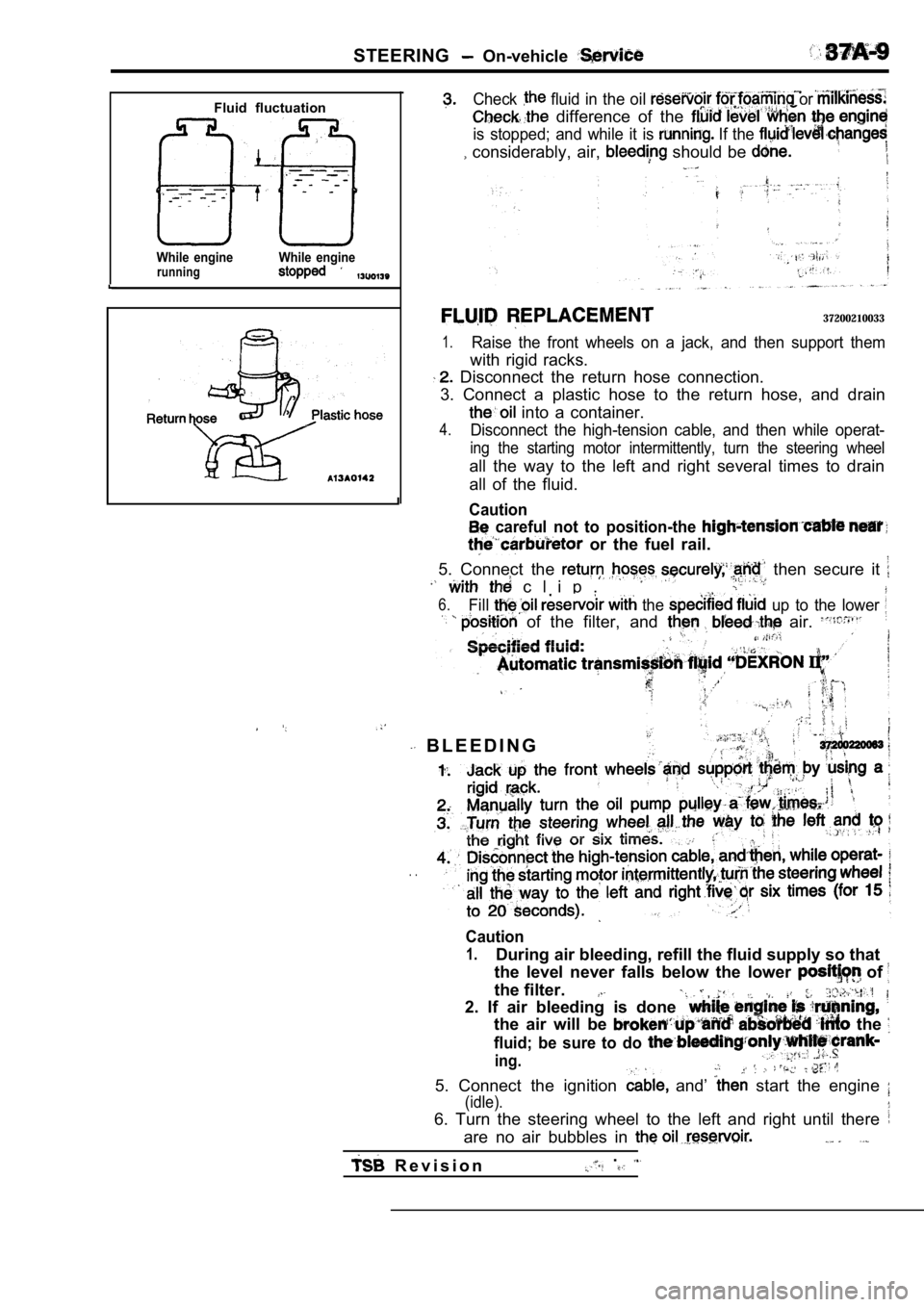
Fluid fluctuation
While enginerunningWhile engine
Check fluid in the oil or
difference of the
is stopped; and while it is If the
considerably, air, should be
37200210033
1.Raise the front wheels on a jack, and then support them
with rigid racks.
Disconnect the return hose connection.
3. Connect a plastic hose to the return hose, and d rain
into a container.
4.Disconnect the high-tension cable, and then while operat-
ing the starting motor intermittently, turn the steering wheel
all the way to the left and right several times to drain
all of the fluid.
Caution
careful not to position-the
or the fuel rail.
5. Connect the then secure it
c l i p .
6.Fill the up to the lower
of the filter, and air.
B L E E D I N G
. .
Caution
1.During air bleeding, refill the fluid supply so tha t
the level never falls below the lower
of
the filter.
2. If air bleeding is done
the air will be the
fluid; be sure to do
ing.
5. Connect the ignition and’ start the engine
(idle).
6. Turn the steering wheel to the left and right un til there
are no air bubbles in
R e v i s i o n.
Page 1803 of 2103
S T E E R I N G P o w e r S t e e r i n g ,
Oil seal 203
Bearing
52
. SEAL
Apply a coating of the fluid the outside of the
oil. seal. Using the special ‘tools,
oil seal into
valve housing..
Specified fluid:
,
B A L L B E A R I N G I N S T A L L A T I O N
Apply a coating of the specified fluid to of the
ball bearing. Using the special tools,
the valve housing.‘ I
fluid:
Automatic Fluid II” .
SEAL RING INSTALLATION
Because the seal rings expand at the time of instal lation,
after by using the tool to compress
the rings, or press down by hand.
I
S E A L
Using the special the oil seal into the valve housing.
In order to eliminate a seal valve hous-
ing alignment surface, the upper oil seal
project outward approximately 1 mm in.)
the housing edge surface. .
END PLUG INSTALLATION
(1) Apply the specified sealant, to the the
e n d p l u g .
Specified ATD Part No. equivalent
(2) Secure the threaded of the
by using a punch.
TSB Revision
Page 1811 of 2103
S T E E R I N G Power Steering Oil
WAVE WASHER INSTALLATION
Fit tabs of the wave washer in concavities
to install the wave washer.of the sideplate
PLATE
up the pin hole of the side plate with the dowel
pin
the oil pump body.
. .
, .
PUMP HOUSING GASKET INSTALLATION
Fit protrusions of the pump housing gasket in conca vities
of the oil pump body to install the pump housing ga sket.
PULLEY INSTALLATION
Use the special tool to secure the pulley, and then install
the pulley lock nut.
TSB Revision
Page 1816 of 2103
203
Drive shaft
ConnectorSide plate
Terminal assembly
Suction connector
mounting portion
of oil pump body
DRIVE PULLEY REMOVAL
Use the special tool to secure the drive pulley, an d then
remove the drive pulley mounting nuts.
REASSEMBLY SERVICE POINTS
SEAL INSTALLATION
DRIVE ASSEMBLY INSTALLATION
Use the special tool to press-fit the drive shaft a ssembly.
O-RINGS INSTALLATION
Apply specified fluid on O-rings.
No. mm (in.)
11 I
I
I
“I
5
Specified fluid:
Automatic transmission Fluid “DEXRON II”
TSB RevisionI
Page 1817 of 2103
STEERING Power Steering Pump Engine (Turbo) and
Terminal assembly
Direct round edgeto the cam
9
PRESSURE SWITCH ASSEMBLY INSTALLATION
Fit the. spring to the oil pump body with the larger diameter
end at. the terminal assembly side.
ROTOR INSTALLATION
Install the rotor to the pulley assembly so that th e rotor’s
punch mark is at the pump cover side.
CAM RING INSTALLATION
Install the cam ring with the punch mark facing the side plate.
VANE INSTALLATION
Install the vanes on the rotor, paying close attention to the
installation direction.
DRIVE PULLEY INSTALLATION
Use the special tool to secure the drive pulley, an d then
install the drive pulley mounting nuts.
TSB Revision