1989 MITSUBISHI GALANT sensor
[x] Cancel search: sensorPage 1130 of 1273
![MITSUBISHI GALANT 1989 Service Repair Manual SERVICE BRAKES - Specifications35-9
SERVICE SPECIFICATIONS [1993 models]
ItemsSOHCDOHC
Standard value
Brake pedal height mm (in.) 176-181 (6.9-7.1)
176-181 (6.9-7.1)
Brake pedal free play mm (in.)3-8 MITSUBISHI GALANT 1989 Service Repair Manual SERVICE BRAKES - Specifications35-9
SERVICE SPECIFICATIONS [1993 models]
ItemsSOHCDOHC
Standard value
Brake pedal height mm (in.) 176-181 (6.9-7.1)
176-181 (6.9-7.1)
Brake pedal free play mm (in.)3-8](/manual-img/19/57312/w960_57312-1129.png)
SERVICE BRAKES - Specifications35-9
SERVICE SPECIFICATIONS [1993 models]
ItemsSOHCDOHC
Standard value
Brake pedal height mm (in.) 176-181 (6.9-7.1)
176-181 (6.9-7.1)
Brake pedal free play mm (in.)3-8 (.I
-.3)3-8 (.I -.3)
Brake pedal to floorboard clearance
mm (in.)80 (3.1) or more 80 (3.1) or more
Proportioning valve pressure MPa
(psi)
Split point 3.95-4.45
(561-633)3.45-3.95 (491-561)
Output pressure5.55-6.05 (789-861)4.65-5.15 (661-732)
[input pressure][8.2 (1 ,I 63)][7.7 (1,095)]
Booster push rod to master cylinder piston clearancemm (in.)
9 inch brake booster0.8-l .O (.031-,039)0.8- 1 .O (.031-.039)
7
+ 8 inch brake booster0.5-0.7 (.020-.028)
Disc brake drag force (tangential force of wheel mounting bolts)
N (Ibs.)70 (15.4) or less 70 (15.4) or less
[Disc brake dragging torque] Nm (ftlbs.)[4 (3) or less] [4 (3) or less]
Speed sensor’s internal resistance
k& -0.8- 1.2*
Clearance between the speed pole piece and the toothed rotor mm (in.) -0.3-0.9 (.012-.035)*
-imit
Left/right proportioning valve output pressure difference
MPa
(psi) 0.4 (57)0.4 (57)
Front disc runout
mm (in.) 0.07 (.0028)0.07 (0028)
Pad thickness mm (in.) 2.0
(.08)2.0 (.08)
Front disc thickness
mm (in.) 22.4 (.882)22.4 (882)
Rear disc thickness
mm(in.) -8.4 (.331)
Rear disc runout
mm (in.) -0.08 (.003 1)
Rear drum lining thicknessmm (in.)1 .O (04)
Rear drum inside diameter
mm (in.) 205 (8.1)
NOTE* : Vehicles with A.B.S.
TSB Revision
Page 1131 of 1273
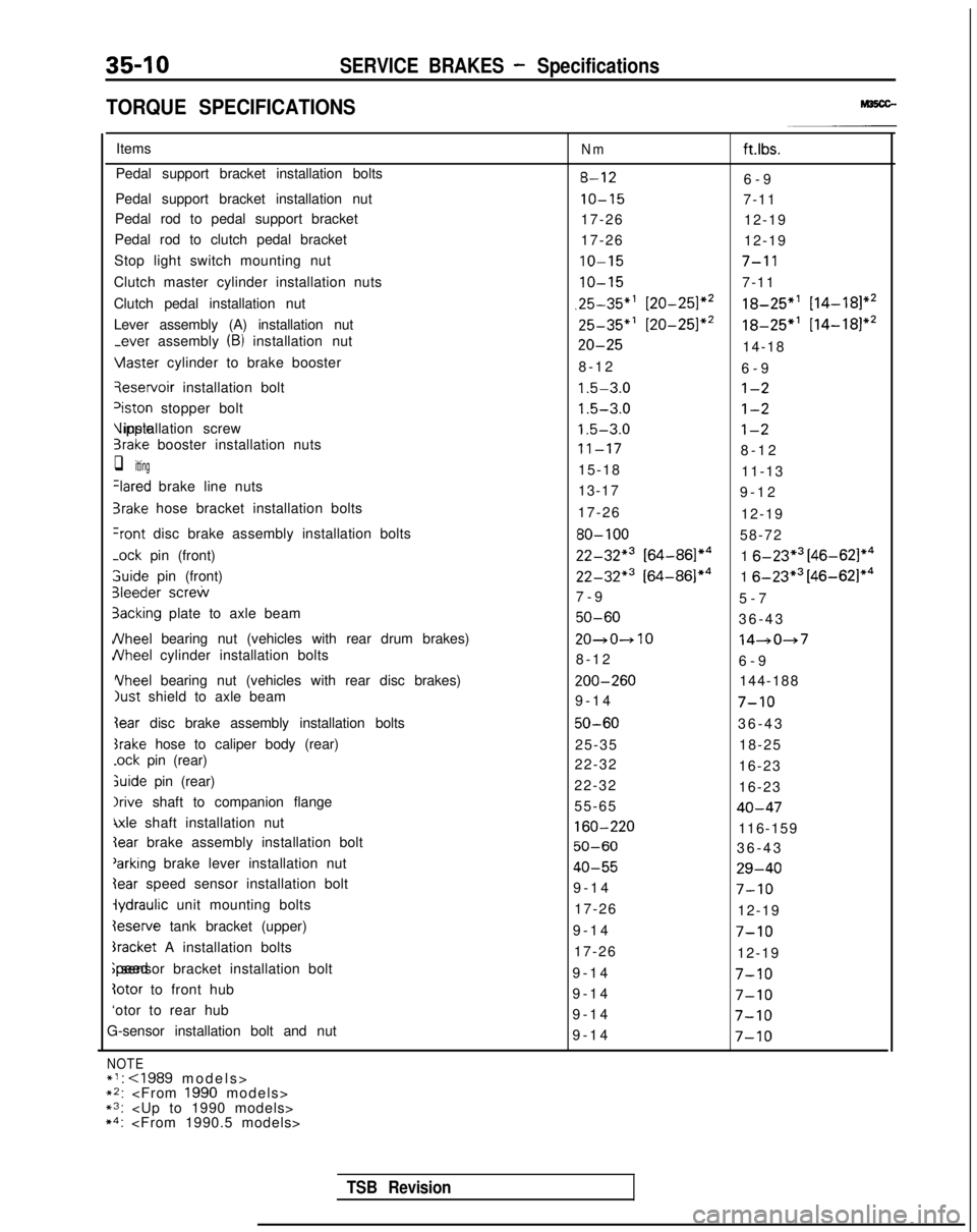
35-10SERVICE BRAKES - Specifications
TORQUE SPECIFICATIONS
Items
Pedal support bracket installation bolts
Pedal support bracket installation nut
Pedal rod to pedal support bracket
Pedal rod to clutch pedal bracket
Stop light switch mounting nut
Clutch master cylinder installation nuts
Clutch pedal installation nut
Lever assembly (A) installation nut
-ever assembly (B) installation nut Vlaster
cylinder to brake booster qeservoir
installation bolt
‘iston stopper bolt Vipple installation screw
3rake booster installation nuts
q itting
Ilared brake line nuts
3rake hose bracket installation bolts
+ont disc brake assembly installation bolts
-ock
pin (front) 3uide
pin (front)
31eeder screw
3acking plate to axle beam
JVheel bearing nut (vehicles with rear drum brakes)
JVheel cylinder installation bolts Yheel
bearing nut (vehicles with rear disc brakes)
just shield to axle beam
Iear disc brake assembly installation bolts
srake hose to caliper body (rear)
.ock pin (rear)
&ride pin (rear)
Irive shaft to companion flange
\xle shaft installation nut
Ieserve tank bracket (upper)
bracket A installation bolts ;peed sensor bracket installation bolt
totor to front hub
‘otor to rear hub
G-sensor installation bolt and nut
NOTE*I:
~2:
Nmft.lbs.
8-126-
9
IO-157-11
17-26 12-19
17-26 12-19
IO-157-l 1
IO-157-11
,25-35”’ [20-251*218-25”’ [14-181*2
25-35*’ [20-251*218-25*’
[14-181*2
20-2514-18
8-1
2
6-9
1.5-3.0l-2
1.5-3.0l-2
1.5-3.0l-2
11-178-1
2
15-18 11-13
13-17 9-12
17-26 12-19
80-10058-72
22-32*3 [64-86]*41 6-23*3 [46-621*4
22-32*3 [64-86]*41 6-23*3 [46-62]*4
7-
9
5-7
50-6036-4
3
20~0~1014-047
8-1
2
6-9 ZOO-260
144-188
9-14
7-10
50-6036-4
3
25-35 18-25
22-32 16-23
22-32 16-23
55-65
40-47
160-220116-159
50-6036-4
3
40-5529-40
9-1
4
7-10
17-26
12-19
9-1
4
7-10
17-26
12-19
9-1
4
7-10
9-1
4
7-10
9-1
4
7-10
9-1
4
7-10
TSB Revision
Page 1138 of 1273
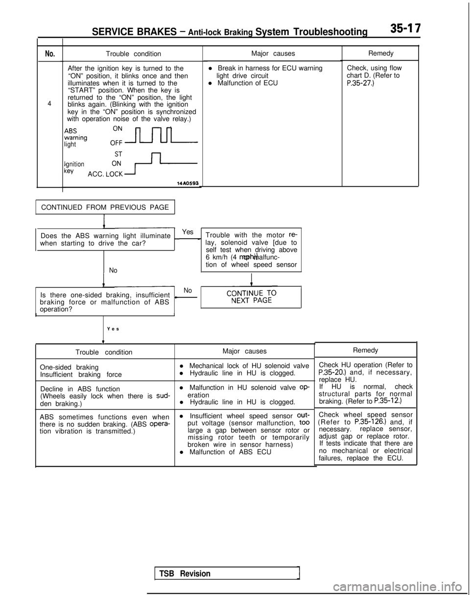
SERVICE BRAKES - Anti-lock Braking System Troubleshooting35-I 7
No.
4
Trouble condition
After the ignition key is turned to the “ON” position, it blinks once and then
illuminates when it is turned to the “START” position. When the key is
returned to the “ON” position, the light
blinks again. (Blinking with the ignition
key in the “ON” position is synchronized
with operation noise of the valve relay.)
ABSwarning
ighto:=
gnition:eyACC. LCFY-
14AO593
Major causes
l Break in harness for ECU warning light drive circuit
l Malfunction of ECU
CONTINUED FROM PREVIOUS PAGE
Does the ABS warning light illuminate
_Yes Trouble with the motor re-
when starting to drive the car?
c lay, solenoid valve [due to self test when driving above
6 km/h (4 mph)] or malfunc-
Notion of wheel speed sensor
I
Is there one-sided braking, insufficientNo
L
braking force or malfunction of ABS
operation?
I
Yes
t
Trouble condition
One-sided braking Insufficient braking force
Decline in ABS function
I
Major causes
l Mechanical lock of HU solenoid valve
l Hydraulic line in HU is clogged.
l Malfunction in HU solenoid valve
op-
(Wheels easily lock when there is sud-
eration
den braking.) l Hydraulic line in HU is clogged.
ABS sometimes functions even when l Insufficient wheel speed sensor out-
there is no sudden braking. (ABS opera-
put voltage (sensor malfunction,
to0
tion vibration is transmitted.)
large a gap between sensor rotor or
missing rotor teeth or temporarily
broken wire in sensor harness)
l Malfunction of ABS ECU Remedy
Check, using flow
chart D. (Refer to
P.35-27.)
Remedy
Check HU operation (Refer to
P.35-20.) and, if necessary,
replace HU. If HU is normal, check
structural parts for normal
braking. (Refer to
P.35-12.)
Check wheel speed sensor
(Refer to P.35-126.) and, if
necessary. replace sensor,
adjust gap or replace rotor. If tests indicate that there are
no mechanical or electrical
failures, replace the ECU.
TSB Revision
Page 1140 of 1273
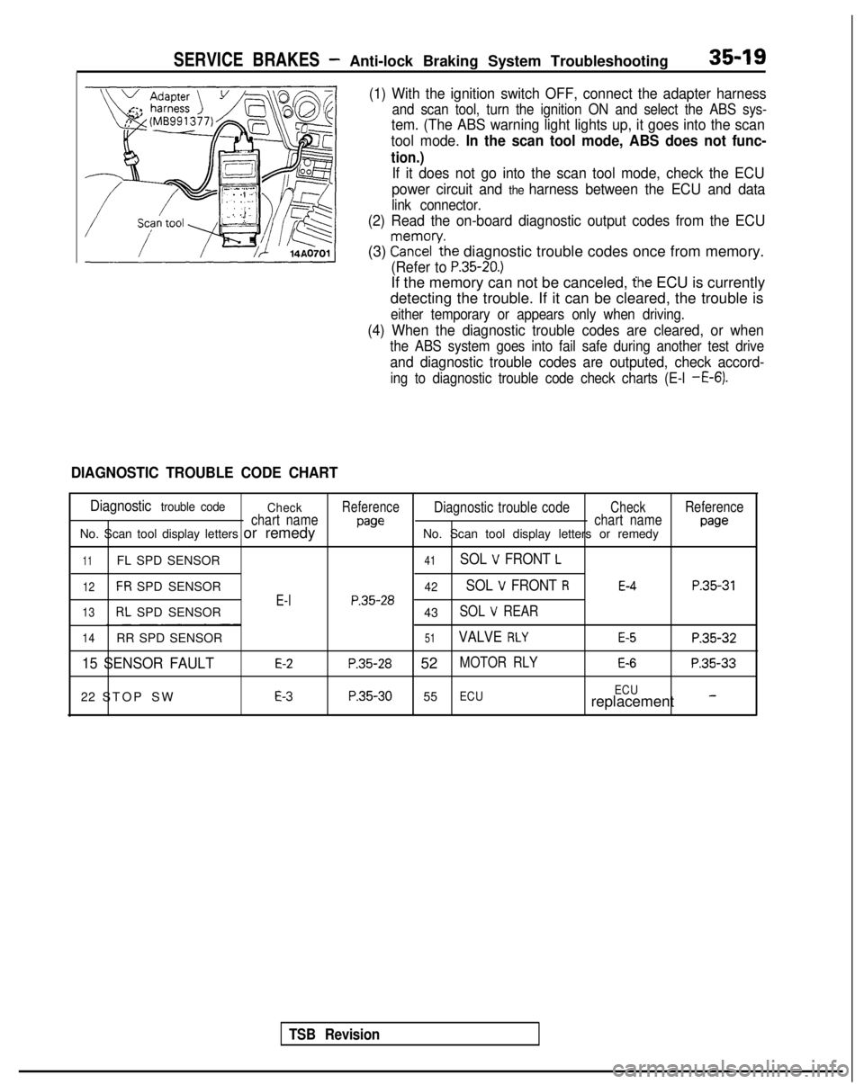
SERVICE BRAKES - Anti-lock Braking System Troubleshooting35-19
(1) With the ignition switch OFF, connect the adapter harness
and scan tool, turn the ignition ON and select the ABS sys-
tem. (The ABS warning light lights up, it goes into the scan
tool mode.
In the scan tool mode, ABS does not func-
tion.)
If it does not go into the scan tool mode, check the ECU
power circuit and
the harness between the ECU and data
link connector.
(2) Read the on-board diagnostic output codes from the ECU
(3) ?a\?zl’ythe diagnostic trouble codes once from memory.
(Refer to P.35-20.)
If the memory can not be canceled, the ECU is currently
detecting the trouble. If it can be cleared, the trouble is
either temporary or appears only when driving.
(4) When the diagnostic trouble codes are cleared, or when
the ABS system goes into fail safe during another test drive
and diagnostic trouble codes are outputed, check accord-
ing to diagnostic trouble code check charts (E-l -E-6).
DIAGNOSTIC TROUBLE CODE CHART
Diagnostic trouble code CheckReferenceDiagnostic trouble codeCheckReference
chart name
pawchart namepawNo. Scan tool display letters or remedy No. Scan tool display letters or remedy
11FL SPD SENSOR41SOL V FRONT L
12FR SPD SENSOR42SOL V FRONT RE-4P.35-31
E-lP.35-2813RL SPD SENSOR
43SOL V REAR
14RR SPD SENSOR51VALVE RLYE-5P.35-32
15 SENSOR FAULTE-2P.35-28 52MOTOR RLYE-6P.35-33
22 STOP SWE-3P.35-30 55ECU ECUreplacement -
TSB Revision
Page 1149 of 1273
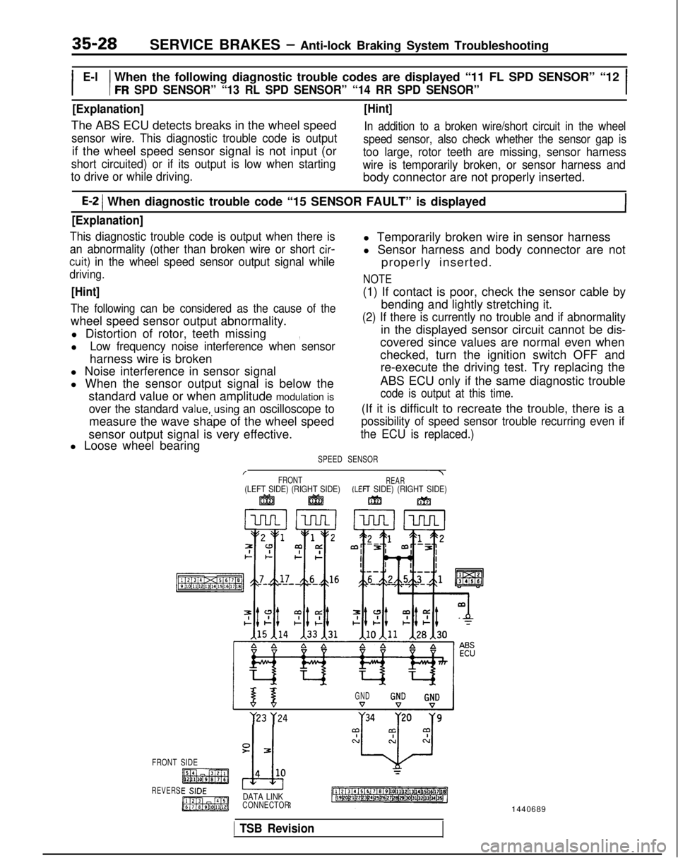
35-28SERVICE BRAKES - Anti-lock Braking System Troubleshooting
E-l
I I
When the following diagnostic trouble codes are displayed “11 FL SPD \
SENSOR” “12
FR SPD SENSOR” “13 RL SPD SENSOR” “14 RR SPD SENSOR”I
[Explanation]
The ABS ECU detects breaks in the wheel speed
sensor wire. This diagnostic trouble code is output
if the wheel speed sensor signal is not input (or
short circuited) or if its output is low when starting
[Hint]
In addition to a broken wire/short circuit in the wheel
speed sensor, also check whether the sensor gap is
too large, rotor teeth are missing, sensor harness
wire is temporarily broken, or sensor harness and
to drive or while driving.
body connector are not properly inserted.
E-2 1 When diagnostic trouble code “15 SENSOR FAULT” is displayed
[Explanation]
This diagnostic trouble code is output when there isl Temporarily broken wire in sensor harness
an abnormality (other than broken wire or short cir-
cuit) in the wheel speed sensor output signal while
l Sensor harness and body connector are not
properly inserted.
driving.NOTE
[Hint](1) If contact is poor, check the sensor cable by
The following can be considered as the cause of thebending and lightly stretching it.
wheel speed sensor output abnormality.
(2) If there is currently no trouble and if abnormality
l Distortion of rotor, teeth missing in the displayed sensor circuit cannot be dis-,
lLow frequency noise interference when sensorcovered since values are normal even when
harness wire is broken checked, turn the ignition switch OFF and
l Noise interference in sensor signal re-execute the driving test. Try replacing the
l When the sensor output signal is below the ABS ECU only if the same diagnostic trouble
standard value or when amplitude modulation is
code is output at this time.
over the standard value,.using an oscilloscope to(If it is difficult to recreate the trouble, there is a
measure the wave shape of the wheel speed
possibility of speed sensor trouble recurring even if
sensor output signal is very effective.the ECU is replaced.)
l Loose wheel bearing
SPEED SENSOR
/~7FRONTREAR(LEFT SIDE) (RIGHT SIDE)(LEFT SIDE) (RIGHT SIDE)ggj ggjjm m
GND y23
y24
FRONT SIDE
REVERSDATA LINKCONNECTOR
1 TSB Revision
1440689
Page 1150 of 1273
SERVICE BRAKES - Anti-lock Braking System Troubleshooting
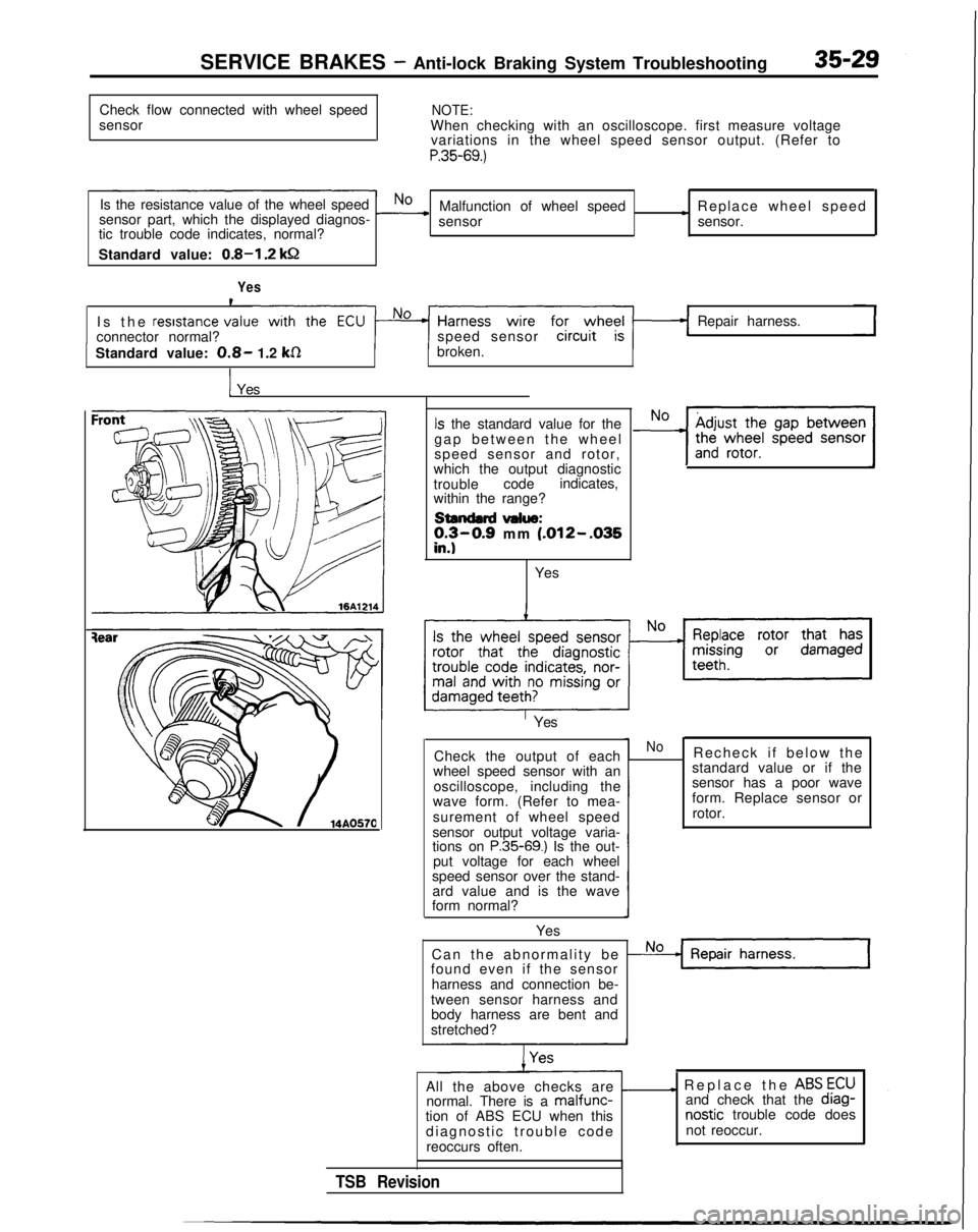
Check flow connected with wheel speed
sensor
NOTE:When checking with an oscilloscope. first measure voltage variations in the wheel speed sensor output. (Refer to
P.35-69.)
Is the resistance value of the wheel speedNosensor part, which the displayed diagnos- -Malfunction of wheel speed) Replace wheel speed
sensor sensor.
tic trouble code indicates, normal?
Standard value:
0.8-I .2 kQ
Yes
Is the
resrstance v
connector normal? speed sensorRepair harness.
Standard value:
0.8- 1.2 kR
I
broken.
I Yes
Is the standard value for the
gap between the whee
l
speed sensor and rotor,
which the output diagnostic
trouble codeindicates,
within the range?
standard value:;y-0.9 mm (.012--035.
Yes
Yes
Check the output of each
wheel speed sensor with an
oscilloscope, including the
wave form. (Refer to mea-
surement of wheel speed
sensor output voltage varia-
tions on
P.35-69.) Is the out-
put voltage for each wheel
speed sensor over the stand- ard value and is the wave
form normal?
Yes
NoRecheck if below th
e
standard value or if the
sensor has a poor wave
form. Replace sensor or
rotor.
Can the abnormality be
Nofound even if the sensor harness and connection be-
tween sensor harness and body harness are bent and
stretched?
All the above checks are
_normal. There is a malfunc-tion of ABS ECU when this diagnostic trouble cod
e
reoccurs often.
I Replace the ABS
ECU
and check that the diag- nostic
trouble code does
not reoccur.
TSB Revision
Page 1156 of 1273
SERVICE BRAKES .- Anti-lock Braking System Troubleshooting35-35
No.
4
rBSvarningght
I!Jnitlonkey
L
Trouble condition
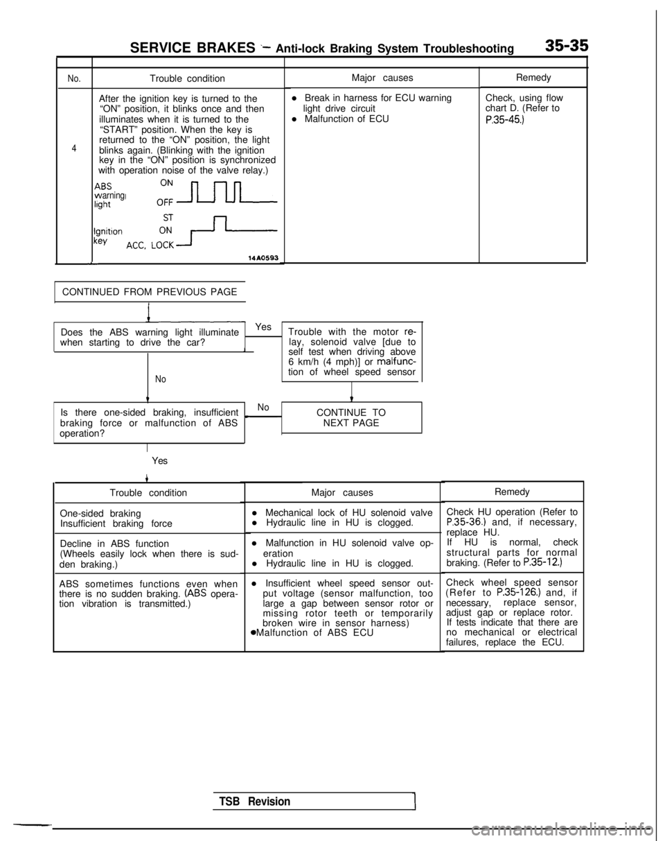
After the ignition key is turned to the “ON” position, it blinks once and then
illuminates when it is turned to the “START” position. When the key is
returned to the “ON” position, the light
blinks again. (Blinking with the ignition
key in the “ON” position is synchronized
with operation noise of the valve relay.)
14A0593
CONTINUED FROM PREVIOUS PAGE Major causes
l Break in harness for ECU warning light drive circuit
l Malfunction of ECU
when starting to drive the car? Does the ABS warning light illuminate
Yes
Trouble with the motor
re-lay, solenoid valve [due to1self test when driving above
6 km/h (4 mph)] or malfunc-
Notion of wheel speed sensor
tt
Is there one-sided braking, insufficientNo
braking force or malfunction of ABS c
CONTINUE TO
NEXT PAGE
operation?
Yes
4
Trouble condition
One-sided braking Insufficient braking force
Decline in ABS function
(Wheels easily lock when there is sud-
den braking.)
ABS sometimes functions even when
there is no sudden braking.
(ABS opera-
tion vibration is transmitted.) Major causes
l Mechanical lock of HU solenoid valve
l Hydraulic line in HU is clogged.
l Malfunction in HU solenoid valve op- eration
l Hydraulic line in HU is clogged.
l Insufficient wheel speed sensor out- put voltage (sensor malfunction, too
large a gap between sensor rotor or
missing rotor teeth or temporarily
broken wire in sensor harness) 8 Malfunction of ABS ECU Remedy
Check, using flow
chart D. (Refer to
P.35-45.)
TSB Revision1
Remedy
Check HU operation (Refer to
P.35-36.) and, if necessary,
replace HU. If HU is normal, check
structural parts for normal
braking. (Refer to
P.35-12.)
Check wheel speed sensor
(Refer to P.35-126.) and, if
necessary, replace sensor,
adjust gap or replace rotor. If tests indicate that there are
no mechanical or electrical
failures, replace the ECU.
Page 1159 of 1273
35-38SERVICE BRAKES - Anti-lock Braking System Troubleshooting
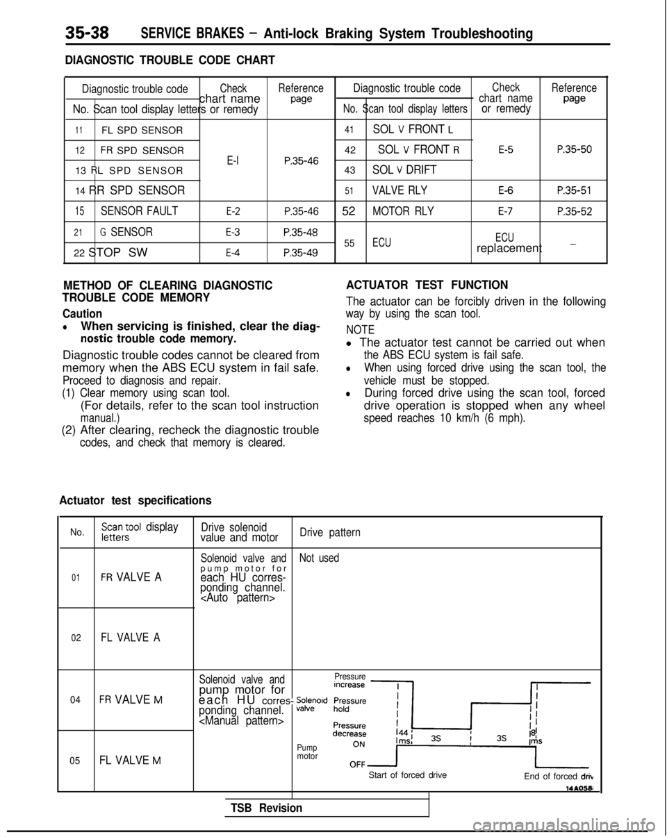
DIAGNOSTIC TROUBLE CODE CHART
Diagnostic trouble codeCheckReferenceDiagnostic trouble codeCheck
Reference
chart namewechart name
No. Scan tool display letters or remedyNo. Scan tool display lettersor remedypage
11FL SPD SENSOR
12FR SPD SENSOR
13
RL SPD SENSOR
14 RR SPD SENSOR
15SENSOR FAULT
21G SENSOR
22 STOP SW
E-l
E-2
E-3
E-4
41SOL V FRONT L
42SOL V FRONT RE-5P.35-50
P.35-4643SOL V DRIFT
51VALVE RLYE-6P.35-51
P.35-46 52MOTOR RLYE-7P.35-52
P.35-4855ECU ECUP.35-49replacement -
METHOD OF CLEARING DIAGNOSTIC
TROUBLE CODE MEMORY
Caution
lWhen servicing is finished, clear the diag-
nostic trouble code memory.
Diagnostic trouble codes cannot be cleared from
memory when the ABS ECU system in fail safe.
Proceed to diagnosis and repair.
(1) Clear memory using scan tool.
(For details, refer to the scan tool instruction
manual.)
(2) After clearing, recheck the diagnostic trouble
codes, and check that memory is cleared.
ACTUATOR TEST FUNCTION
The actuator can be forcibly driven in the following
way by using the scan tool.
NOTE
l The actuator test cannot be carried out when
the ABS ECU system is fail safe.
lWhen using forced drive using the scan tool, the
vehicle must be stopped.
lDuring forced drive using the scan tool, forced
drive operation is stopped when any wheel
speed reaches 10 km/h (6 mph).
Actuator test specifications
No.FGc$ool displayDrive solenoidvalue and motorDrive pattern
Solenoid valve and Not used
01FR VALVE Apump motor fo
r
each HU corres-ponding channel.
02FL VALVE A
Solenoid valve andPressure
04FR VALVE Mpump motor for
each HU corres- %Fwidponding channel.
05FL VALVE M
Pumpmotor
TSB Revision
Start of forced drive End of forced drib 14AO581