1989 MITSUBISHI GALANT sensor
[x] Cancel search: sensorPage 1167 of 1273
35-46SERVICE BRAKES - Anti-lock Braking System TroubleshootingE-l
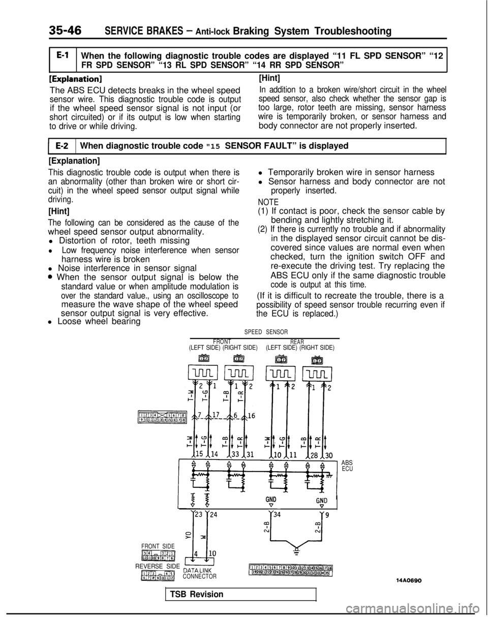
When the following diagnostic trouble codes are displayed “11 FL SPD \
SENSOR” “12
FR SPD SENSOR” “13 RL SPD SENSOR” “14 RR SPD SENSOR”
[Explanation] [Hint]
The ABS ECU detects breaks in the wheel speedIn addition to a broken wire/short circuit in the wheel
sensor wire. This diagnostic trouble code is output
if the wheel speed sensor signal is not input (or
speed sensor, also check whether the sensor gap is
too large, rotor teeth are missing, sensor harness
short circuited) or if its output is low when starting wire is temporarily broken, or sensor harness and
to drive or while driving.
body connector are not properly inserted.
E-2When diagnostic trouble code "15 SENSOR FAULT” is displayed
[Explanation]
This diagnostic trouble code is output when there is
an abnormality (other than broken wire or short cir-
cuit) in the wheel speed sensor output signal while
driving.
[Hint]
The following can be considered as the cause of the
wheel speed sensor output abnormality. l Distortion of rotor, teeth missing
lLow frequency noise interference when sensor
harness wire is broken
l Noise interference in sensor signal
0 When the sensor output signal is below the
standard value or when amplitude modulation is
over the standard value., using an oscilloscope to
measure the wave shape of the wheel speed
sensor output signal is very effective.
l Loose wheel bearing l Temporarily broken wire in sensor harness
l Sensor harness and body connector are not
properly inserted.
NOTE
(1) If contact is poor, check the sensor cable by
bending and lightly stretching it.
(2) If there is currently no trouble and if abnormality
in the displayed sensor circuit cannot be dis-
covered since values are normal even when
checked, turn the ignition switch OFF and
re-execute the driving test. Try replacing the
ABS ECU only if the same diagnostic trouble
code is output at this time.
(If it is difficult to recreate the trouble, there is a
possibility of speed sensor trouble recurring even if
the ECU is replaced.)
SPEED SENSOR
FRONT
REAR(LEFT SIDE) (RIGHT SIDE) (LEFT SIDE) (RIGHT SIDE)
ABS
ECU
GNDG!D
r23 )‘24 ;34Y9
FRONT SIDE
REVERSE SIDE DATA LlNK
CONNECTOR
14A0690
TSB Revision
Page 1168 of 1273
SERVICE BRAKES - Anti-lock Braking System Troubleshooting35-47
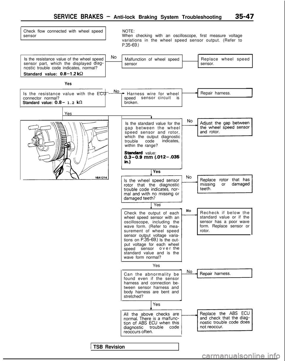
Check flow connected with wheel speed
sensorNOTE:When checking with an oscilloscope, first measure voltage
variations in the wheel speed sensor output. (Refer to
P.35-69.)
Is the resistance value of the wheel speedNoMalfunction of wheel speed . Replace wheel speed
sensor part, which the displayed diag-
sensor sensor.nostic
trouble code indicates, normal?
Standard value:
0.8-I .2 kSZ
Yes
Is the resistance value with the ECU No* Harness wire for wheel
connector normal? speedsensor circuitis
Standard value: 0.8- 1.2 k0broken.
I
Repair harness.
t
Is the standard value for the
gap between the whee
l
speed sensor and rotor,
which the output diagnostic
trouble codeindicates,
within the range?
stendllrd value:!I$0.9 mm (.012- .035
) YesI
1 Yes.
Check the output of each
wheel speed sensor with an
oscilloscope, including the
wave form. (Refer to mea-
surement of wheel speed
sensor output voltage varia-
tions on
P.35-69.) Is the out-
put voltage for each wheel
speed sensor over
thestandard value and is the
wave form normal?
Yes
Can the abnormality b
e
found even if the sensor
harness and connection be-
tween sensor harness and body harness are bent and
stretched? No
-Recheck if below th
e
standard value or if the
sensor has a poor wave
form. Replace sensor or
rotor.
1 TSB Revision
Page 1169 of 1273
![MITSUBISHI GALANT 1989 Service Repair Manual 35-48SERVICE BRAKES - Anti-lock Braking System Troubleshooting
I IE-3When diagnostic trouble code “21 G SENSOR” is displayedI
[Explanation]
The ABS ECU outputs this diagnostic trouble code
in the MITSUBISHI GALANT 1989 Service Repair Manual 35-48SERVICE BRAKES - Anti-lock Braking System Troubleshooting
I IE-3When diagnostic trouble code “21 G SENSOR” is displayedI
[Explanation]
The ABS ECU outputs this diagnostic trouble code
in the](/manual-img/19/57312/w960_57312-1168.png)
35-48SERVICE BRAKES - Anti-lock Braking System Troubleshooting
I IE-3When diagnostic trouble code “21 G SENSOR” is displayedI
[Explanation]
The ABS ECU outputs this diagnostic trouble code
in the following cases.
lOFF trouble turning G sensor OFF (It is judged
that the
G sensor continues to be OFF for more
than approximately 13 seconds except when the
vehicle is stopped or when there is stop light
switch input.
lWhen there is a broken wire or short circuit in
the harness for the
G sensor system.
ABSPOWERRELAY
MAIN FUSIBLEIGNITIONLINK @SWITCH (IG2)
G-SENSOR
q
ABS ECU
II21314 15161 ~/819110111l12l1P/14l15~~6l17l16~~19120121122123l24125l26l27128129/30131j32b3134(15~14AO702
Is G sensor normal?(Refer to P.35-132.)
NoReplace G sensor.
1 Yes
Remove the ABS ECUconnector and check atthe harness connector.
I
With the ignition key “ON”No m The harness between thedoes the voltage betweenG sensor and the ABS
terminal No.6
and ground
ECU is broken.
indicate battery voltage?
Yes
*
Repair harness.
Replace ABS ECU.
1 TSB Revision
Page 1175 of 1273
35-54SERVICE BRAKES - Service Adjustment Procedures
F14519
14UOO61
When engine isstopped
No good
0
w
\/‘14UOO62z;redengine
is
14UOO60 ,3.
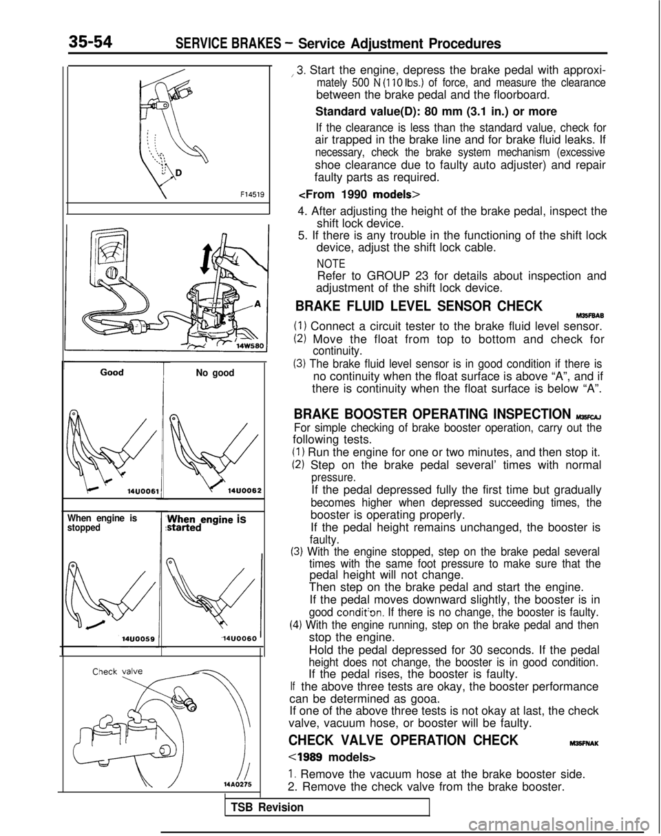
Start the engine, depress the brake pedal with approxi-
mately 500 N (110 Ibs.) of force, and measure the clearance
between the brake pedal and the floorboard.
Standard value(D): 80 mm (3.1 in.) or more
If the clearance is less than the standard value, check for
air trapped in the brake line and for brake fluid leaks. If
necessary, check the brake system mechanism (excessive
shoe clearance due to faulty auto adjuster) and repair
faulty parts as required.
4. After adjusting the height of the brake pedal, inspect the shift lock device.
5. If there is any trouble in the functioning of the shift lock device, adjust the shift lock cable.
NOTE
Refer to GROUP 23 for details about inspection and
adjustment of the shift lock device.
BRAKE FLUID LEVEL SENSOR CHECKM35F6A6
(1) Connect a circuit tester to the brake fluid level sensor.
(2) Move the float from top to bottom and check for
continuity.
(3) The brake fluid level sensor is in good condition if there is
no continuity when the float surface is above “A”, and if
there is continuity when the float surface is below “A”.
BRAKE BOOSTER OPERATING INSPECTION MlKcAJ
For simple checking of brake booster operation, carry out the
following tests.
(1) Run the engine for one or two minutes, and then stop it.
(2) Step on the brake pedal several’ times with normal
pressure.
If the pedal depressed fully the first time but gradually
becomes higher when depressed succeeding times, the
booster is operating properly.
If the pedal height remains unchanged, the booster is
faulty.
(3) With the engine stopped, step on the brake pedal several
(4
If
times with the same foot pressure to make sure that the
pedal height will not change.
Then step on the brake pedal and start the engine.
If the pedal moves downward slightly, the booster is in
good condit’on. If there is no change, the booster is faulty.
.) With the engine running, step on the brake pedal and then
stop the engine.
Hold the pedal depressed for 30 seconds. If the pedal
height does not change, the booster is in good condition.
If the pedal rises, the booster is faulty.
the above three tests are okay, the booster performance
can be determined as gooa.
If one of the above three tests is not okay at last, the check
valve, vacuum hose, or booster will be faulty.
CHECK VALVE OPERATION CHECKM3!3FNAK
cl989 models>
1. Remove the vacuum hose at the brake booster side.
2. Remove the check valve from the brake booster.
TSB Revision
Page 1189 of 1273
35-68SERVICE BRAKES - Service Adjustment Procedures
A.B.S. warning light
Ignition switch
sT;!i;%
lARD175
Filter4
kR
14A0171
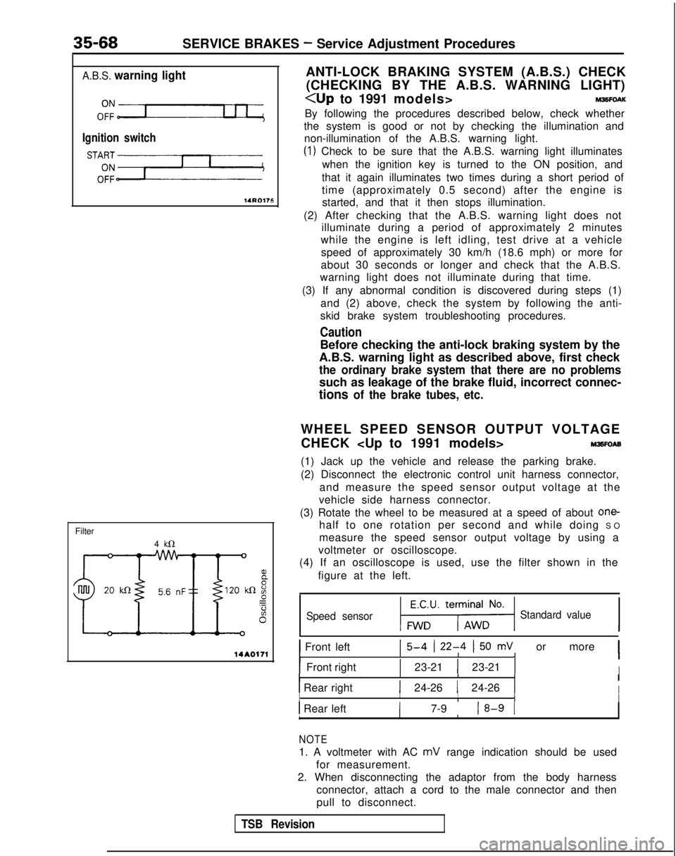
ANTI-LOCK BRAKING SYSTEM (A.B.S.) CHECK
(CHECKING BY THE A.B.S. WARNING LIGHT)
By following the procedures described below, check whether
the system is good or not by checking the illumination and non-illumination of the A.B.S. warning light.
(1) Check to be sure that the A.B.S. warning light illuminates
when the ignition key is turned to the ON position, and
that it again illuminates two times during a short period of
time (approximately 0.5 second) after the engine is started, and that it then stops illumination.
(2) After checking that the A.B.S. warning light does not illuminate during a period of approximately 2 minutes
while the engine is left idling, test drive at a vehicle
speed of approximately 30 km/h (18.6 mph) or more for
about 30 seconds or longer and check that the A.B.S.
warning light does not illuminate during that time.
(3) If any abnormal condition is discovered during steps (1) and (2) above, check the system by following the anti-
skid brake system troubleshooting procedures.
Caution
Before checking the anti-lock braking system by the
A.B.S. warning light as described above, first check
the ordinary brake system that there are no problems
such as leakage of the brake fluid, incorrect connec-
tions of the brake tubes, etc.
WHEEL SPEED SENSOR OUTPUT VOLTAGE
CHECK
M3sFoAE
(1) Jack up the vehicle and release the parking brake.
(2) Disconnect the electronic control unit harness connector,
and measure the speed sensor output voltage at the
vehicle side harness connector.
(3) Rotate the wheel to be measured at a speed of about
one-
half to one rotation per second and while doing S
O
measure the speed sensor output voltage by using a
voltmeter or oscilloscope.
(4) If an oscilloscope is used, use the filter shown in the
figure at the left.
Speed sensor1-1 Standard value
1 Front left15-4 (22-4 I50 mV or more 1IIIII
IFront rightI1 23-21 1 23-21 1IIIII1 Rear right1 24-26 1 24-26 1II IIIIII Rear left( 7-9 18-9 1IIII1
NOTE
1. A voltmeter with AC mV range indication should be used
for measurement.
2. When disconnecting the adaptor from the body harness connector, attach a cord to the male connector and then
pull to disconnect.
TSB Revision
Page 1190 of 1273
SERVICE BRAKES - Service Adjustment Procedures35-69
(5) The probable cause if the output voltage is 50 mV or lower, or if the one-side deflection width of the
oscilloscope’s waveform is 70
mV or lower
Probable causes Remedy
Excessive clearance between the speed sensor pole
piece and rotor Adjust to the standard value.
Foreign material attached to the speed sensor pole
pieceRemove the foreign material.
Damaged speed sensor pole pieceReplace the speed sensor.
Damaged rotor teeth~~~ rReplace the rotor.
Loose speed sensor or rotor installation bolt I
Tighten to the specified torque.
1
NOTE
The speed sensor internal resistance and harness side are normal.
Caution
It is conceivable, because the movement of a speed-sensor cable “foll\
ows” the movement of the front
or rear suspension, that the damaged wiring condition may be apparent on\
ly during travel on poor
road surfaces, and may be normal on better road surfaces. Therefore, whe\
n measuring the output
voltage of a speed sensor, recheck the condition of the cable connection\
s by removing the clamp and pulling the cable and bending it near the clamp position in order to che\
ck for the existence of damaged
wiring.
1/21314j51617)61Q~10~11~12)13~14~15)16~17~1~~19~20~21~22~23~24~25~26(27~26~2Q~30(31~32~33~34~35~
Check connector
74=f=n
ECU
*
Body harnessMB991 356fl 14N018C
MEASUREMENT OF WHEEL SPEED SENSOR
OUTPUT VOLTAGE
IWSFOAQ
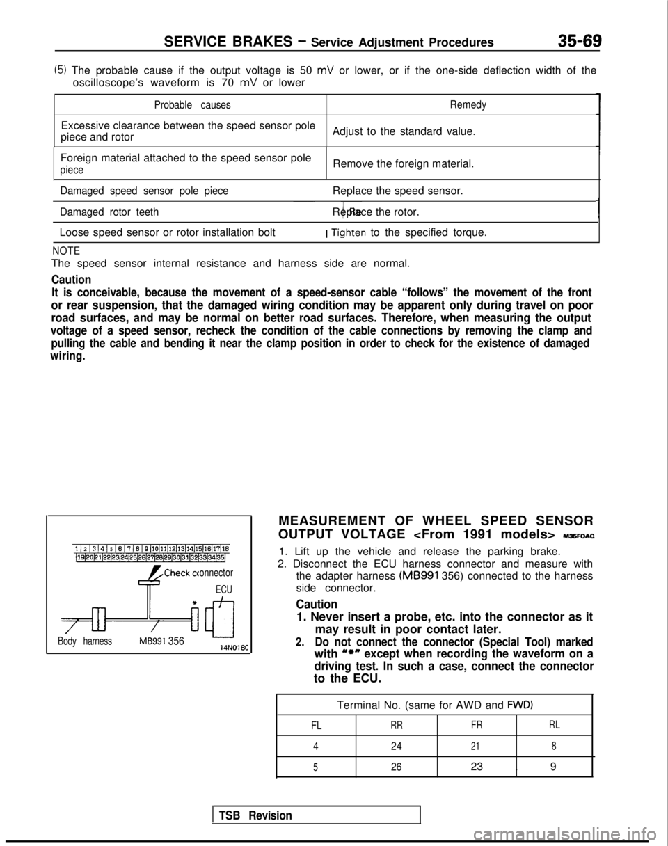
1. Lift up the vehicle and release the parking brake.
2. Disconnect the ECU harness connector and measure with the adapter harness (MB991
356) connected to the harness
side connector.
Caution
1. Never insert a probe, etc. into the connector as it
may result in poor contact later.
2.Do not connect the connector (Special Tool) marked
with u*nexcept when recording the waveform on a
driving test. In such a case, connect the connector
to the ECU.
Terminal No. (same for AWD and
FWD)
FL
RR FRRL
4
24218
5
2623 . 9
TSB Revision
Page 1191 of 1273
35-70SERVICE BRAKES- Service Adjustment Procedures
I, ! I ! I4 IO II IIWhen turned manually :---;---i-.-l---L--.I 8 ! IaI 1 11 1 II ’I 1’ I I I;-;--1---:--‘---+---t---i ’I IL---)-.-i---+--.II ’ I I 1 , 1 ,I
--:--~---;---:---~--~--
POINTS IN WAVEFORM MEASUREMENT
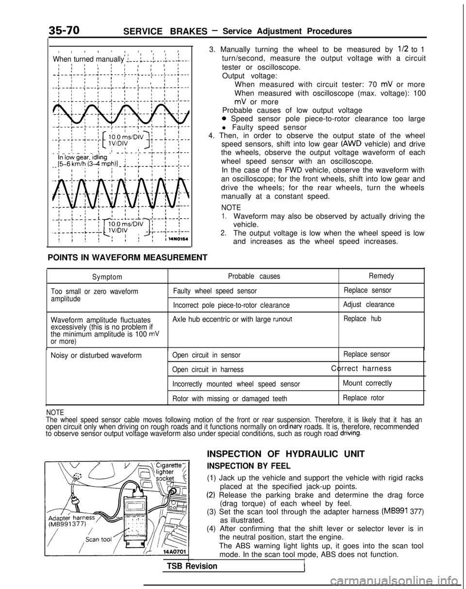
3. Manually turning the wheel to be measured by
l/2 to 1
turn/second, measure the output voltage with a circuit
tester or oscilloscope. Output voltage: When measured with circuit tester: 70
mV or more
When measured with oscilloscope (max. voltage): 100
mV or more
Probable causes of low output voltage
0 Speed sensor pole piece-to-rotor clearance too large
l Faulty speed sensor
4. Then, in order to observe the output state of the wheel
speed sensors, shift into low gear
(AWD vehicle) and drive
the wheels, observe the output voltage waveform of each
wheel speed sensor with an oscilloscope.
In the case of the FWD vehicle, observe the waveform with
an oscilloscope; for the front wheels, shift into low gear and
drive the wheels; for the rear wheels, turn the wheels manually at a constant speed.
NOTE
1.Waveform may also be observed by actually driving the
vehicle.
2.The output voltage is low when the wheel speed is low
and increases as the wheel speed increases.
Symptom
Too small or zero waveform amplitude Probable causes
Faulty wheel speed sensor Remedy
Replace sensor
Incorrect pole piece-to-rotor clearanceAdjust clearance
Waveform amplitude fluctuates Axle hub eccentric or with large runoutReplace hub
excessively (this is no problem if
the minimum amplitude is 100 mVor more)
Noisy or disturbed waveformOpen circuit in sensor Replace
sensor
Open circuit in harness
Correct harness
Incorrectly mounted wheel speed sensorMount correctly
Rotor with missing or damaged teeth Replace rotor
NOTEThe wheel speed sensor cable moves following motion of the front or rear\
suspension. Therefore, it is likely that it
has anopen circuit only when driving on rough roads and it functions normally \
on ordinan/ roads. It is, therefore, recommended
to observe sensor output voltage waveform also under special conditions,\
such as rough road dnvlng.
TSB Revision
INSPECTION OF HYDRAULIC UNIT
INSPECTION BY FEEL
(1) Jack up the vehicle and support the vehicle with rigid racks
placed at the specified jack-up points.
(2) Release the parking brake and determine the drag force(drag torque) of each wheel by feel.
(3) Set the scan tool through the adapter harness
(MB991 377)
as illustrated.
(4) After confirming that the shift lever or selector lever is in the neutral position, start the engine.
The ABS warning light lights up, it goes into the scan tool mode. In the scan tool mode, ABS does not function.
I
Page 1202 of 1273
SERVICE BRAKES - Master Cylinder35-81
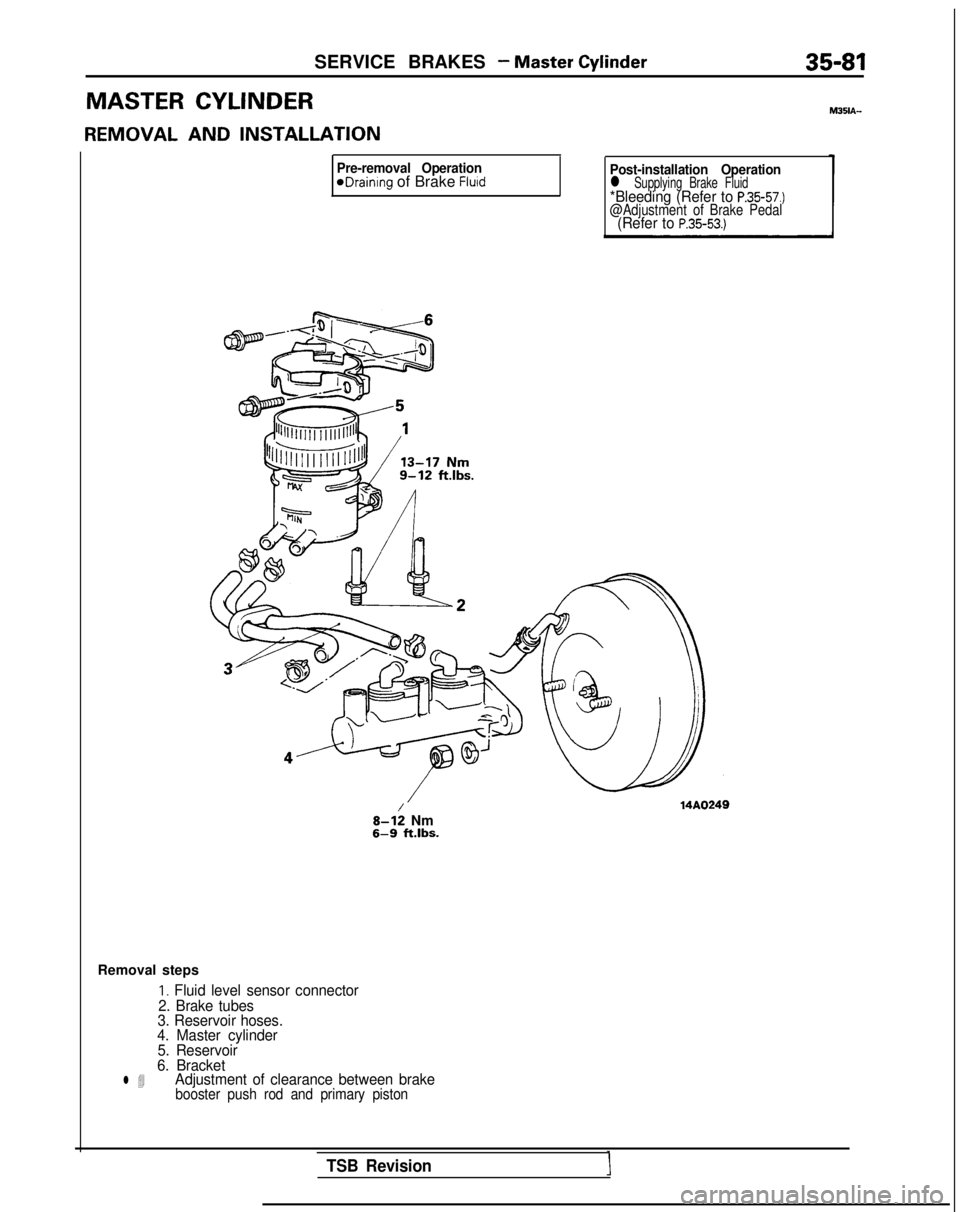
MASTER CYLINDER
REMOVAL AND
INSTALLATION
Pre-removal OperationeDrainIng of Brake FluidPost-installation Operationl Supplying Brake Fluid*Bleeding (Refer to P.3557.)@Adjustment of Brake Pedal(Refer to P.35-53.)
8-l: Nm6-9
ft.lbs. M351A-
Removal steps
I. Fluid level sensor connector
2. Brake tubes
3. Reservoir hoses.
4. Master cylinder
5. Reservoir
6. Bracket
l 4Adjustment of clearance between brakebooster push rod and primary piston
TSB Revision