Page 1204 of 1273
SERVICE BRAKES - Master Cvlinder35-83
DISASSEMBLY AND REASSEMBLY
L1.5-3.0
Nm
1-2 ft.lbs./
-11m
-?
1‘5. 1.5-3.0
Nm
l-2 ft.lbs.
10
(up to 1990.5 models)>
IBrake master cylinder kit
3rake fluid: Conforming to DOT3 or DOT4
14Ao!575
Disassembly steps
1. Reservoir cap assembly
2. Diaphragm
3. Reservoir cap
4. Filter ;: FELte fluid level sensor
7. Reservoir
I)+8.Nipples9.Reservoir seals4*10.Piston stopper bolt
11.Gasketl *12. Piston stopper ringI 3. Primary piston assemblya*14. Secondary piston assembly15. Master cylinder body
CautionDo not disassemble the primary and secondary pistonassembly.
TSB Revision
Page 1206 of 1273
SERVICE BRAKES - Brake Booster35-85
BRAKE BOOSTER
REMOVAL AND INSTALLATION
MJSJA--
Pre-removal Operation
12@Draining of Brake Fluid
-!3\
Cl989 models> 6-9 ft.lbs. A 1
Post-installation Operation6upplying Brake Fulid*Bleeding (Refer to P.35-57.)l Adjustment of Brake Pedal(Refer to P.35-53.)15-18
Nrh ‘7II-13 ftlbs. :From
1990 models>
15-18 Nm 7II-13 ft.lbs.
Removal steps
1. Brake fluid level sensor connector
2. Brake tube
3. Master cylinder, hose, reservoir assembly +*
l +4. Vacuum hose5. Check valve
+* l +6. Vacuum hose with check valve7. Fitting
8. Cotter pin
9. Washer 10.
Clevis pi
n
11. Sealer
c*
12. Proportioning valve installation bolt
13. Brake tube (front left) installation bolt
14. Brake booster
14A05360
.a
QI1 II ;‘,:
4%14u0050
14Y626
Sealant: 3M ATD Part No.8663or equivalent
TSB Revision
Page 1235 of 1273
35-114SERVICE BRAKES - Rear Disc Brake
REAR DISC BRAKE
IEMOVAL AND INSTALLATIO
N
9-1
4 Nm
50-60Nm7-10
ft.lbs.
36-43 ft.lbs.
13-17 Nm9- 12 ft.lbs.
200-260
Nm144-199 ft.lbs.
Removal steps
1. Parking brake cable connection4,2. Brake hose connection
3. Rear brake assembly
4. Rear brake disc
5. Hub cap
l * 6. Wheel bearing nut
7. Washer
8. Rear speed sensor bracket
9. Rear hub assembly
14. Dust shield
I
Pre-removal Operation
*Draining of Brake Fluid
I
TSB RevisionI
Page 1236 of 1273
SERVICE BRAKES - Rear Disc Brake
35-115
50-60 Nm
55-65 Nm39-47 ft.lbs.
Removal steps
1. Parking brake cable connectionl *2. Brake hose connection
3. Rear brake assembly
4. Rear brake disc
~~ H10. Self locking nutl +11. Companion flange
12. Rear speed sensor
4* l +13. Rear axle shaft
14. Dust shield
TSB Revision
Pre-removal Operationl Draining of Brake Fluid
I1Post-installation Operationl Filling of Brake Fluid and Air Bleed-ing (Refer to P.35-57.)l Adjustment of Parking Brake Lever
I Siioke
(Refer to GROUP
36-Service
Ad-I1 justment Procedures.)I
Page 1247 of 1273
35-126 SERVICE BRAKES - Wheel Speed Sensor
WHEEL SPEED SENSOR M35oVAE
REMOVAL AND INSTALLATION
9-14 Nm
7-10 ft.lbs.
9- ldNm7- 10 ft.lbs.
~~Q!-yJl~~@
9-14 N
m
7- 10
ft.lbs.
14A0615
Pre-removal and Post-installation
Operation
@Removal and Installation of theSplash Shield(Refer to GROUP
42-Fender.)
Front speed sensor removal steps
4w1. Front toothed rotor2. Clip3. Connection for front speed sensor
l e e+ 4. Front speed sensorl +5. Front speed sensor bracket
Rear speed sensor removal steps
*I)6. Rear toothed rotor 7. Clip
8. Cable band
9. Connection for rear speed sensor
+e l + 10. Rear speed sensorw+ 11. Rear speed sensor bracket
TSB Revision
/-..
Page 1248 of 1273
Pre-removal and Post-installation
SERVICE BRAKES - Wheel Speed Sensor 35-127
2
7-10 ftlbs.
7-10 ft.lbs.
9-14 Nm
Front speed sensor removal steps
*I)1. Front toothed rotor
2. Clip
+* l a3. Front speed sensor connection
**4. Front speed sensor 5. Front speed sensor bracket
14AO616
Rear speed sensor removal steps
6. Rear toothed rotor (Refer to GROUP 27-Rear Axle Hub)
7. Clip
8. Cable band
l * I)49. Rear speed sensor connection10. Rear speed sensor
12. O-ring
TSB Revision
Page 1249 of 1273

35-128 SERVICE BRAKES - Wheel Speed Sensor
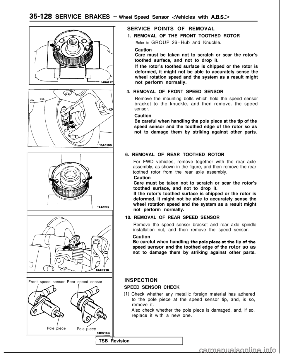
II 14AO215
Front speed sensor Rear speed sensorINSPECTION
Pole
hiecePole &ce
-
SERVICE POINTS OF REMOVAL 1. REMOVAL OF THE FRONT TOOTHED ROTOR Refer to GROUP
26-Hub and Knuckle.
Caution Care must be taken not to scratch or scar the rotor’s
toothed surface, and not to drop it.
If the rotor’s toothed surface is chipped or the rotor is
deformed, it might not be able to accurately sense the
wheel rotation speed and the system as a result might not perform normally.
4. REMOVAL OF FRONT SPEED SENSOR Remove the mounting bolts which hold the speed sensor
bracket to the knuckle, and then remove. the speed
sensor.
Caution
Be careful when handling the pole piece at the tip of the
speed sensor and the toothed edge of the rotor so as not to damage them by striking against other parts.
6. REMOVAL OF REAR TOOTHED ROTOR For FWD vehicles, remove together with the rear axle
assembly, as shown in the figure, and then remove the rear
toothed rotor from the rear axle assembly.
Caution
Care must be taken not to scratch or scar the rotor’s
toothed surface, and not to drop it. If the rotor’s toothed surface is chipped or the rotor is
deformed, it might not be able to accurately sense the
wheel rotation speed and the system as a result might not perform normally.
10. REMOVAL OF REAR SPEED SENSOR Remove the speed sensor bracket and rear axle spindle
installation nut, and then remove the speed sensor.
Caution Be careful when handling
the pole piece at the tip of the
speed sensor and the toothed edge of the
rotor so as
not to damage them by striking against other parts.
SPEED SENSOR CHECK
(1) Check whether any metallic foreign material has adhered to the pole piece at the speed sensor tip, and, is so,remove it.
Also check whether the pole piece is damaged, and, if so, replace it with a new one.
1 TSB Revision
Page 1250 of 1273

SERVICE BRAKES - Wheel Speed Sensor 35-129
:FWD>
Front
Rear (left)
Rear (right)
NOTE
14AOO46
The pole piece can become magnetized because of the
magnet built into the speed sensor, with the result that
metallic foreign material easily adheres to it. Moreover,
the pole piece may not be able to function to correctly
sense the wheel rotation speed if it is damaged.
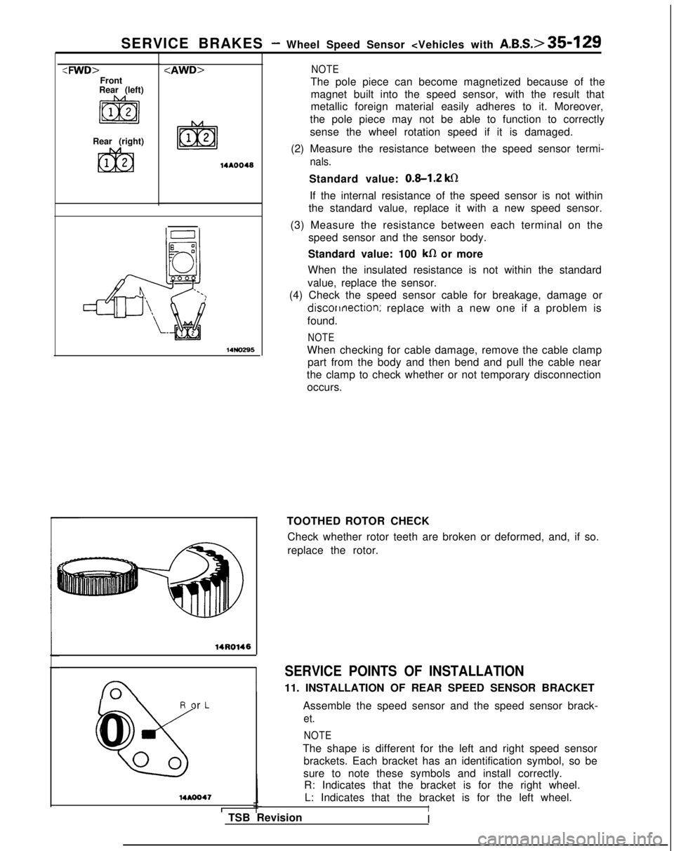
(2) Measure the resistance between the speed sensor termi-
nals. 14NO295
14R0146
R or L
%
0
00
14AOO47
ITSB RevisionStandard value:
0.8-1.2 ks1
If the internal resistance of the speed sensor is not within
the standard value, replace it with a new speed sensor.
(3) Measure the resistance between each terminal on the speed sensor and the sensor body.
Standard value: 100
kfI or more
When the insulated resistance is not within the standard
value, replace the sensor.
(4) Check the speed sensor cable for breakage, damage or discorrnection;
replace with a new one if a problem is
found.
NOTE
When checking for cable damage, remove the cable clamp part from the body and then bend and pull the cable near
the clamp to check whether or not temporary disconnection occurs.
TOOTHED ROTOR CHECK Check whether rotor teeth are broken or deformed, and, if so.
replace the rotor.
SERVICE POINTS OF INSTALLATION
11. INSTALLATION OF REAR SPEED SENSOR BRACKET
Assemble the speed sensor and the speed sensor brack-
et.
NOTE
The shape is different for the left and right speed sensorbrackets. Each bracket has an identification symbol, so be
sure to note these symbols and install correctly. R: Indicates that the bracket is for the right wheel.
L: Indicates that the bracket is for the left wheel.
I
I